
CNC Machined Cam Plates, Planned From Your Drawing
SUUXIANG reviews CNC machined cam plates for DFM, critical dimensions, process routing, and inspection requirements before production.
Representative Components for CNC Machined Cam Plate Development





Related Components and Drawing-Based Quotation


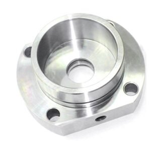


CNC Machined Cam Plates: Drawing-First Advantages
Production planning focuses on the dimensions, process decisions and evidence that matter before machining begins.
DFM Before Quotation
We review drawing clarity, machining access, material requirements and critical features before discussing a production route or quotation.
Critical Dimension Planning
Datums, tolerance relationships and functional interfaces are identified early to align setup strategy, machining allowances and inspection methods.
Integrated Process Routes
CNC machining, EDM, precision grinding and fitting are planned together when geometry, material condition or finish requirements call for them.
Inspection Matched to Risk
Inspection planning follows the agreed critical dimensions, datum scheme and reporting needs so documentation reflects the verified order requirements.
Visible Revision Control
Drawing revisions, technical questions and delivery coordination remain visible throughout the project to help prevent avoidable manufacturing misunderstandings.
Cam Plates and Precision Part Families
Configurable machining and tooling categories for teams managing critical dimensions, mating interfaces, revision control, and inspection requirements.

CNC Machining Services
Precision CNC machining services for drawing-based cam plates, mold parts, connector tooling, and die components. Each project begins with review of material, critical dimensions, datum references, tool access, quantity, and inspection requirements before a process route is proposed.
Upload a Drawing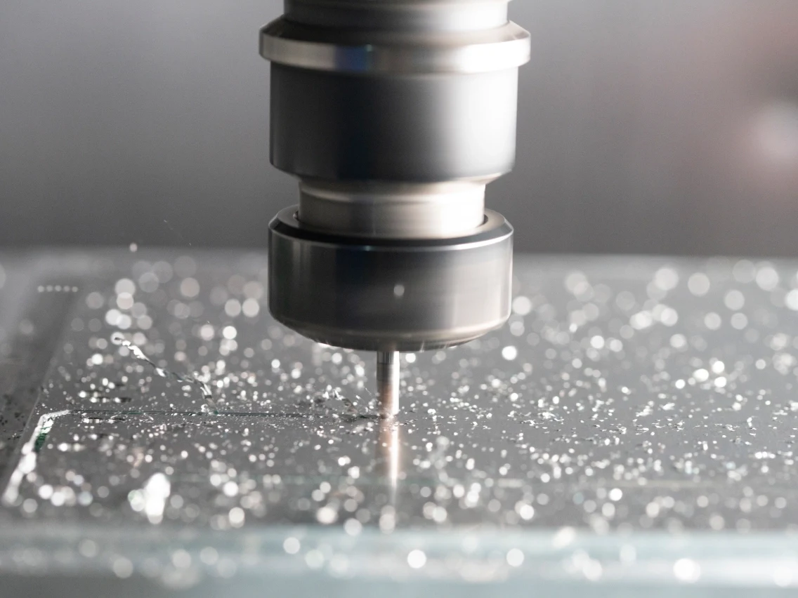
CNC Milling
Custom CNC milling services support prismatic plates, pockets, angled features, mounting patterns, and complex mold-component geometry. Machining strategy is evaluated against workholding, cutter access, remaining stock for grinding, and the datums needed to control functional relationships.
Upload a Drawing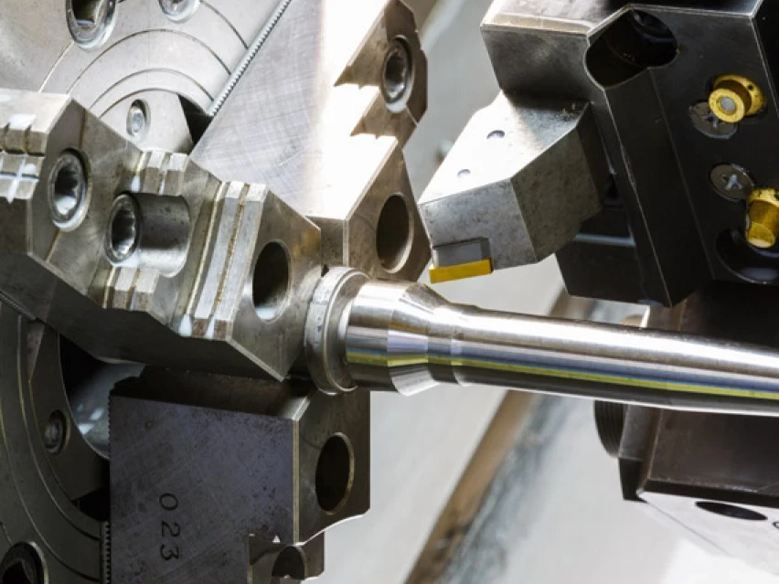
CNC Turning
Precision CNC turning services produce rotational features such as pins, bushings, sleeves, shafts, and locating elements. Buyers should define diameter tolerances, concentricity or runout needs, material condition, surface requirements, and any post-machining heat treatment or grinding steps.
Upload a Drawing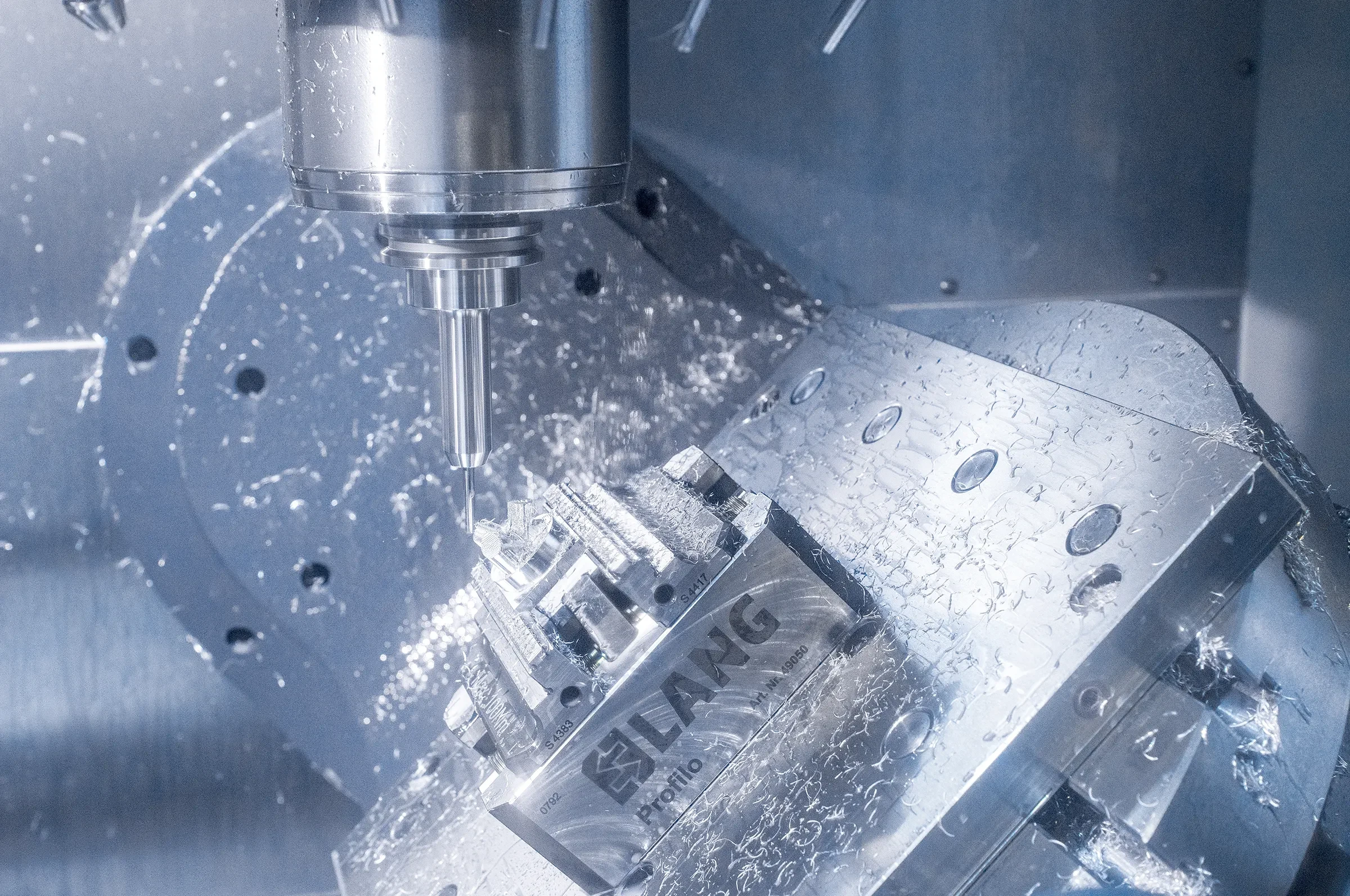
5-Axis Machining
5-axis CNC machining helps reach compound angles, contoured faces, and multi-sided features with fewer setups where the geometry justifies it. Tool orientation, fixture clearance, tolerance relationships, and inspection access are reviewed before selecting the machining approach.
Upload a Drawing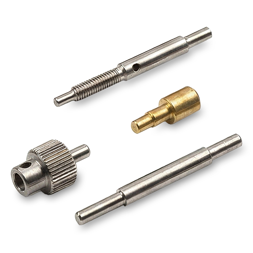
Swiss & Micro Machining
Swiss machining and micro machining address small, slender, and detail-intensive parts used in mold and connector applications. Drawings should identify critical diameters, burr limits, cross holes, thread details, mating conditions, and handling or inspection requirements for delicate features.
Upload a Drawing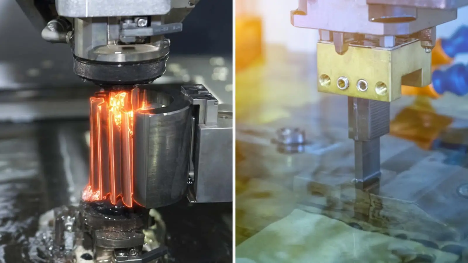
Wire & Sinker EDM
Wire EDM and sinker EDM services support sharp internal profiles, narrow slots, hardened materials, deep features, and geometry inaccessible to conventional cutters. Electrode design, wire path, corner conditions, recast-layer considerations, and finish requirements should be defined during review.
Upload a Drawing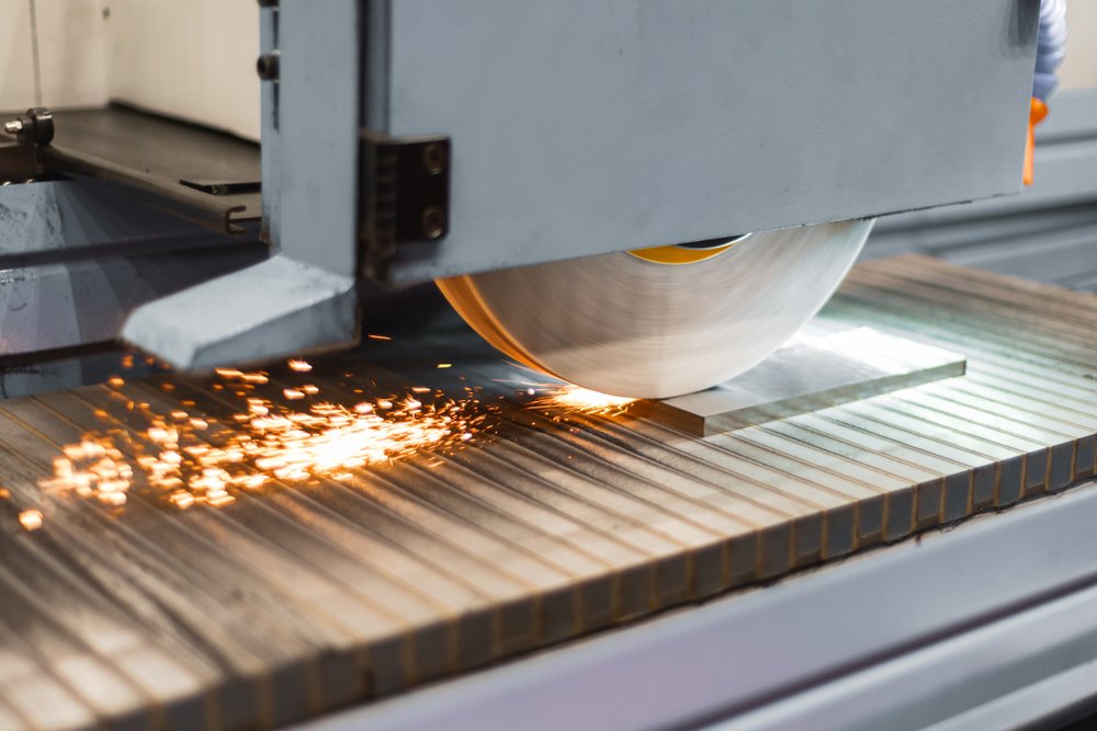
Precision Grinding
Precision surface and profile grinding controls flatness, parallelism, profile accuracy, and finished dimensions on cam plates, inserts, and die components. The process plan considers heat-treatment distortion, machining allowance, clamping effects, datum sequence, and the specified inspection method.
Upload a Drawing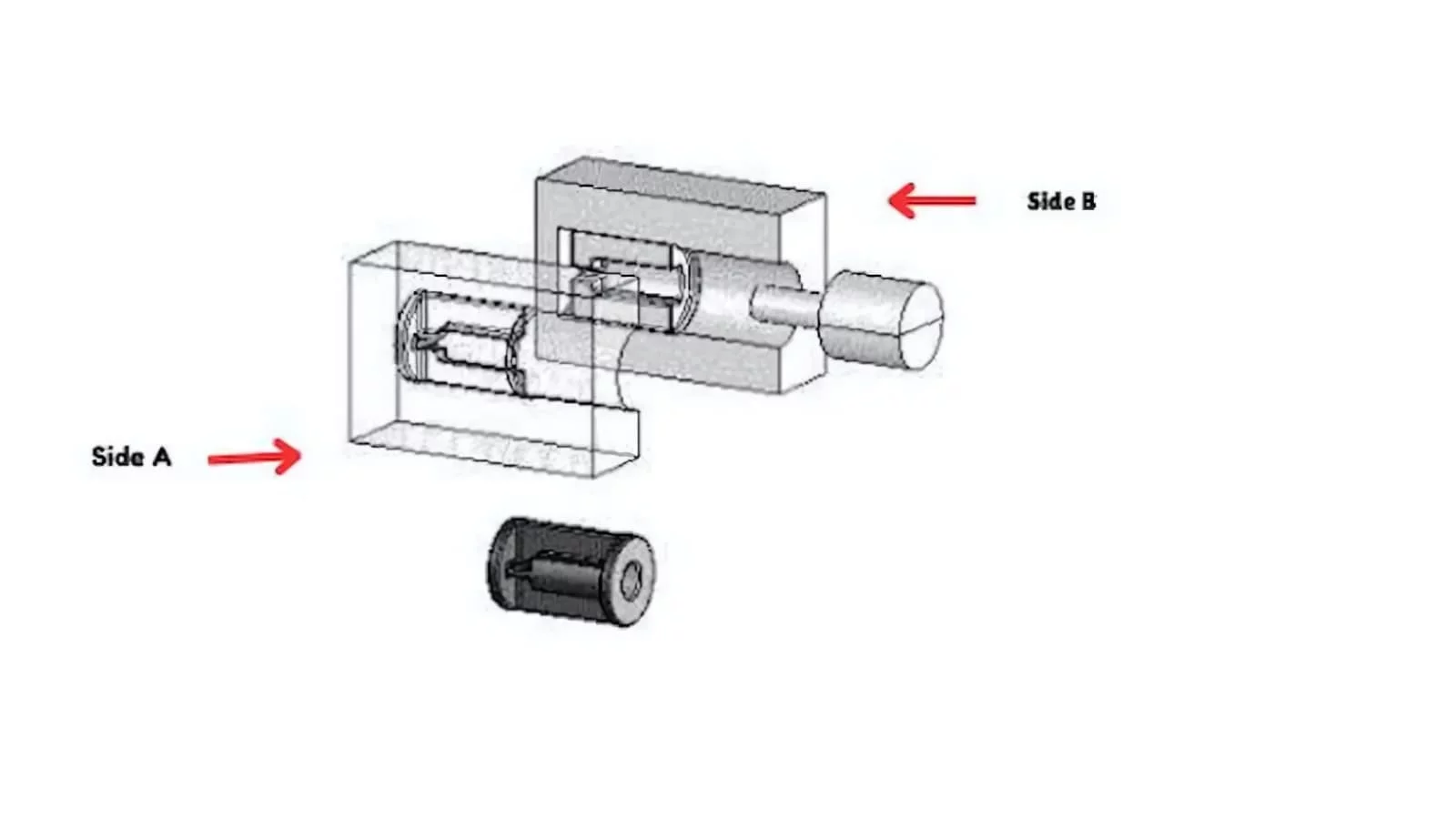
Mold Core & Cavity Inserts
Precision mold core and cavity inserts are manufactured from customer drawings and application requirements. Review focuses on parting surfaces, shutoffs, cooling or venting details, material and hardness condition, EDM or grinding needs, and the dimensions that govern molded-part function.
Upload a Drawing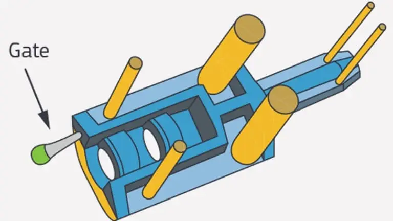
Ejector & Ejection Components
Ejector pins, sleeves, and ejection components are configured around fit, stroke, guidance, wear conditions, and mating geometry. Material, hardness, surface condition, clearance strategy, and critical diameters must be confirmed to support dependable assembly and replacement planning.
Upload a Drawing
Core Pins, Guide & Locating Components
Core pins, guide pins, and locating components require controlled interfaces across mold assemblies. SUUXIANG reviews positional datums, fit class, straightness, concentricity, engagement length, and material treatment requirements so the components can be manufactured and inspected against their drawing intent.
Upload a Drawing
Slides, Lifters, Gates & Mold Accessories
Mold slides, lifters, gates, and accessories are made to drawing-defined travel, shutoff, bearing, and interface requirements. Manufacturing planning considers sliding surfaces, angled relationships, wear areas, assembly clearances, heat treatment, and finishing operations required for the specified design.
Upload a Drawing
Connector Mold Components
Precision connector mold components support tooling where small pitches, repeated cavities, alignment features, and mating interfaces demand disciplined dimensional control. RFQs should include critical dimensions, material and heat-treatment requirements, assembly context, surface requirements, and relevant inspection expectations.
Upload a Drawing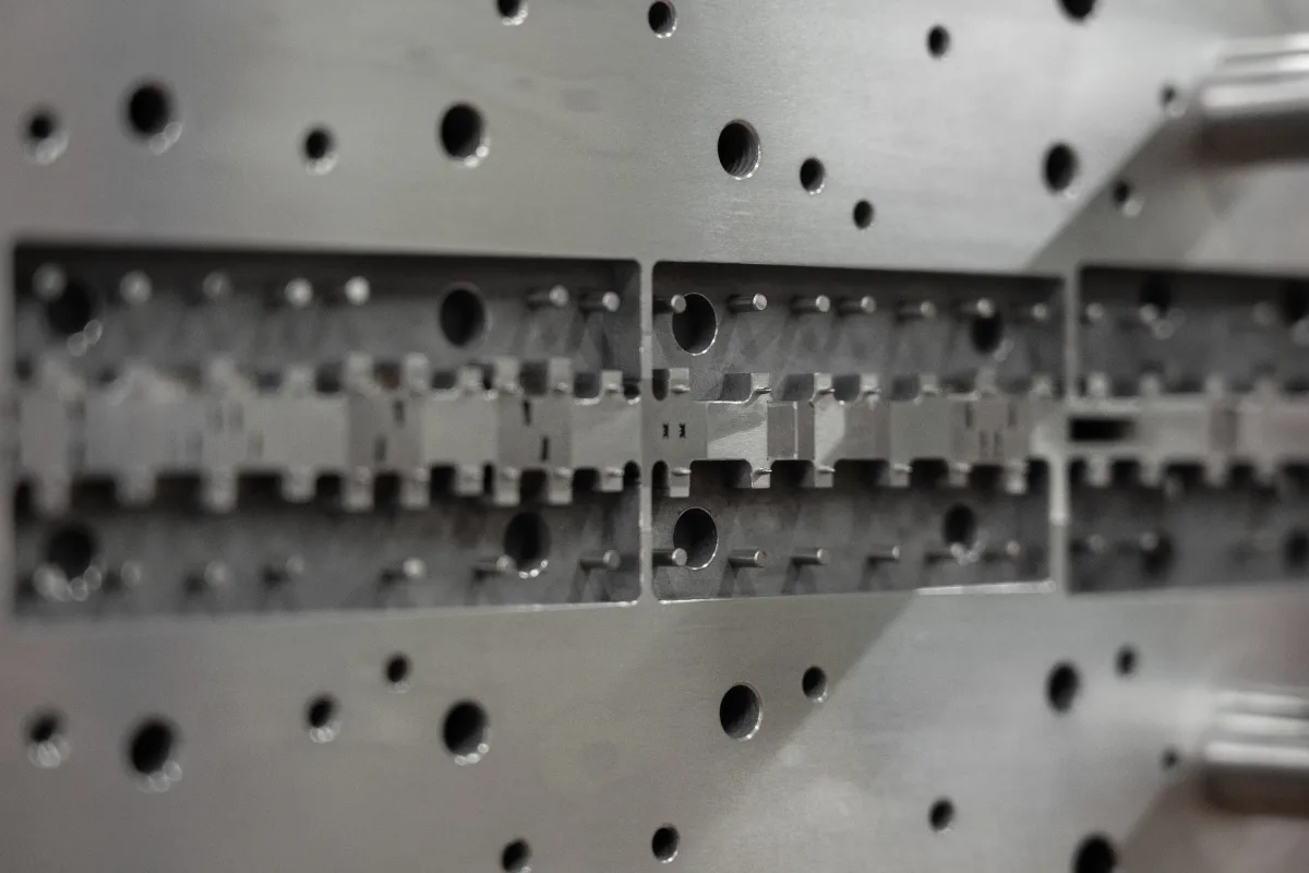
Stamping Die Components
Precision stamping die components include drawing-based punches, inserts, guide elements, plates, and forming-related parts. Process planning accounts for cutting or forming edges, material condition, hardness, grinding stock, EDM access, clearance relationships, and the datums used during die assembly.
Upload a Drawing
Injection, MIM, CIM & Overmolding Tooling
Injection, MIM, CIM, and overmolding tooling components are considered within verified production scope. Project review addresses feed or gate requirements, cavity and core interfaces, shrinkage-related design inputs supplied by the customer, material condition, finishing needs, and component-level inspection criteria.
Upload a Drawing
Machining Materials
CNC machining materials are selected against the drawing, application, strength, wear, corrosion, electrical, and heat-treatment requirements. Material availability and traceability expectations should be provided with the RFQ, especially where a specified grade, condition, or mill documentation affects acceptance.
Upload a Drawing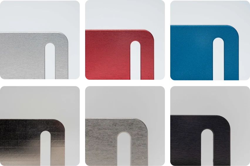
Surface Finishes & Heat Treatment
Surface finishing and heat treatment are planned as part of the dimensional process route, not treated as afterthoughts. Buyers should specify finish targets, coating or treatment requirements, hardness range, masking needs, cosmetic restrictions, and which dimensions require control before or after treatment.
Upload a Drawing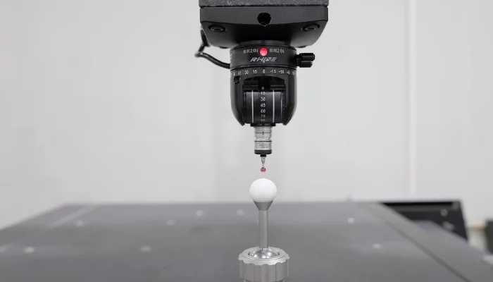
Quality, Metrology & Documentation
Precision inspection, metrology, and quality documentation are aligned with the order’s verified requirements. Define critical dimensions, datum scheme, sampling or reporting expectations, measurement method where necessary, material documentation, revision status, and any customer format required for final records.
Upload a Drawing
Prototyping & Low-Volume Production
Rapid prototyping and low-volume manufacturing support evaluation, tooling development, controlled design changes, and bridge quantities. A useful RFQ includes current drawings and models, quantity, material, delivery target, revision history, critical dimensions, surface requirements, and the inspection evidence needed for approval.
Upload a DrawingMaterials for CNC Machined Cam Plates
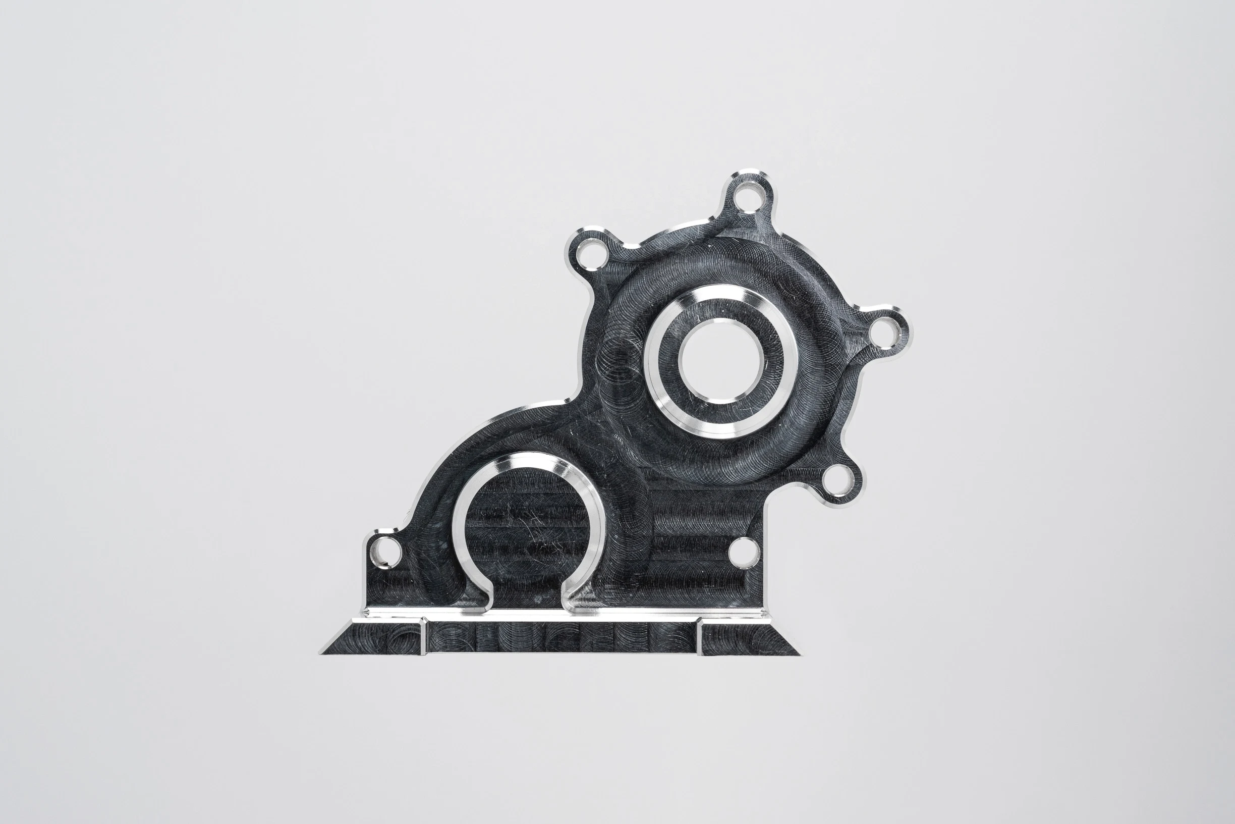
6061-T6 Aluminum
A practical choice for lightweight CNC machined cam plates in fixtures, covers, and moderate-load mechanisms. It machines efficiently and offers useful corrosion resistance; confirm anodizing needs, bearing interfaces, and thread-loading requirements from the drawing.
7075 Aluminum Alloy
Specified when a higher-strength aluminum plate is needed for weight-sensitive mechanical assemblies. Its machinability supports detailed profiles, while corrosion protection and stress-sensitive features should be reviewed against the operating environment and finishing requirement.
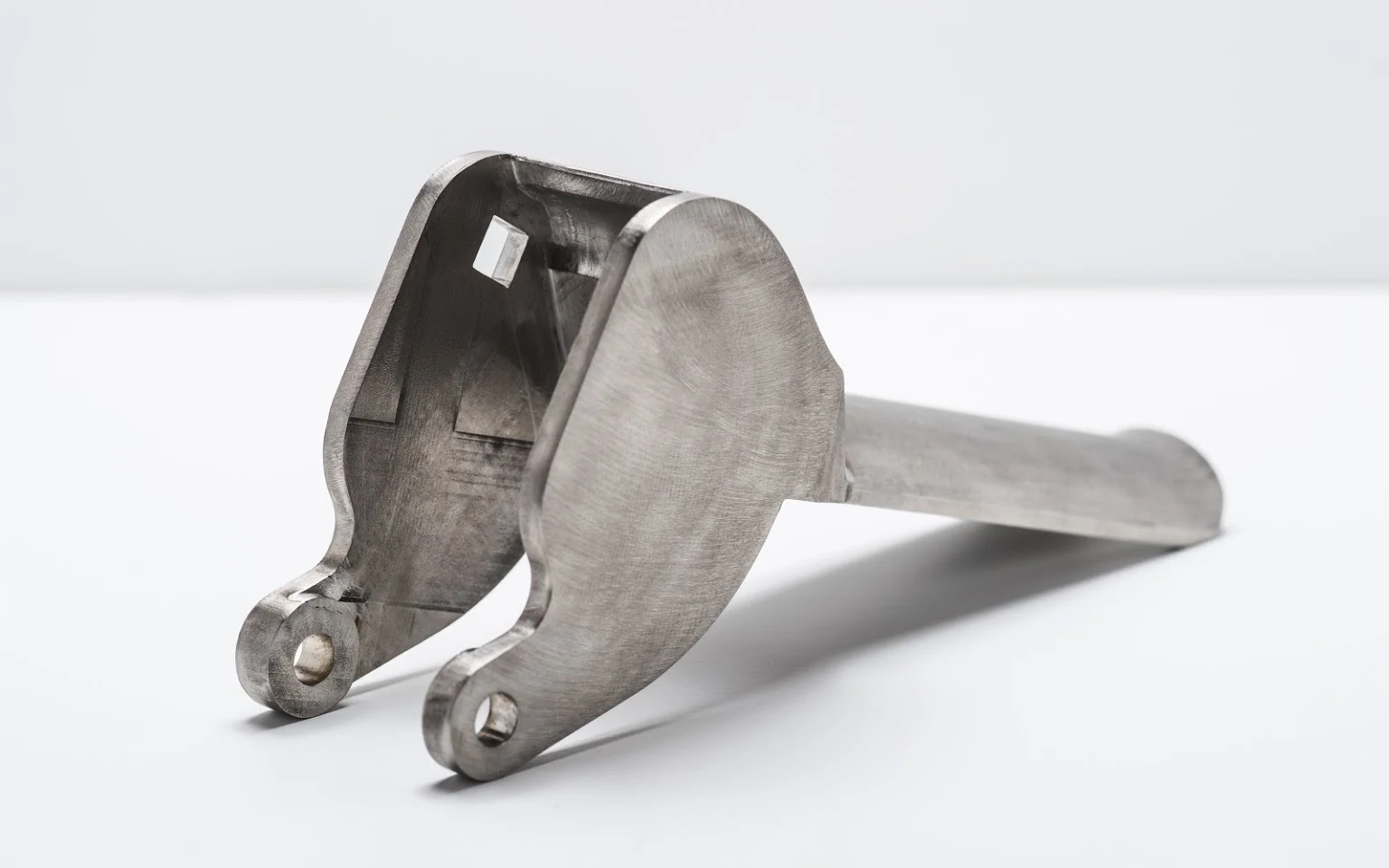
4140 Alloy Steel
Suitable for cam plates requiring stronger load-bearing sections, robust threads, or improved wear performance after an appropriate heat-treatment route. Machining allowance, target hardness, and grinding of critical faces must be defined before process planning.
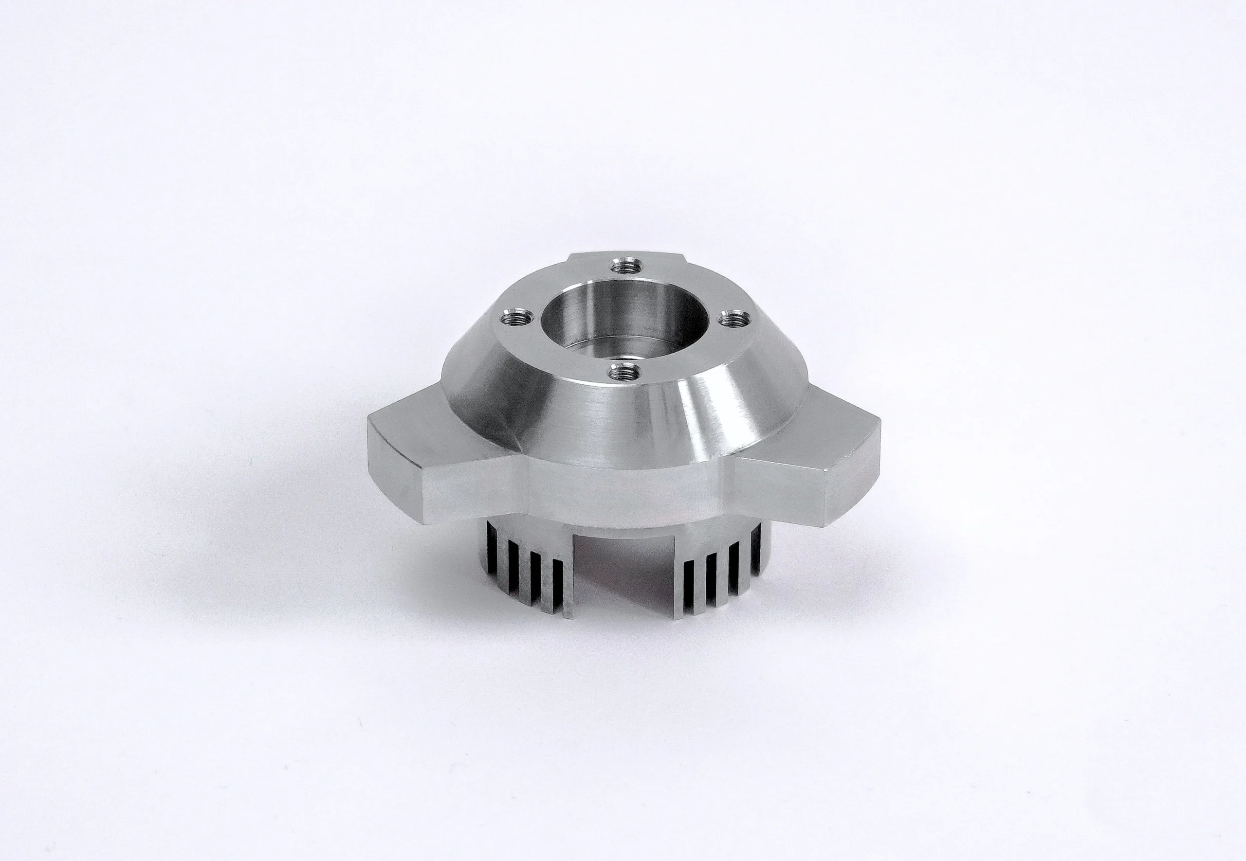
Stainless Steel Grades
Considered for CNC machined cam plates exposed to moisture, chemicals, or cleanliness-sensitive environments. Grade selection affects corrosion resistance, machinability, and heat response, so specify the operating medium, surface finish, and required material standard.
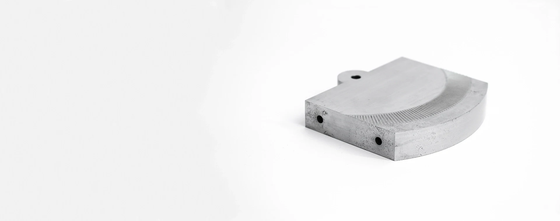
Tool Steel Grades
Used where repeated contact, sliding wear, or dimensional stability makes a hardened material route appropriate. SUUXIANG reviews the selected grade, heat-treatment sequence, EDM needs, and grinding stock against critical dimensions before committing to manufacture.
CNC Machined Cam Plates: Process Routes for Complex Geometry
CNC Milling
CNC milling establishes plate profiles, pockets, faces, bolt patterns, and accessible functional features. Tool selection and fixture strategy are reviewed against datum references, wall geometry, and tool access before production.
CNC Turning
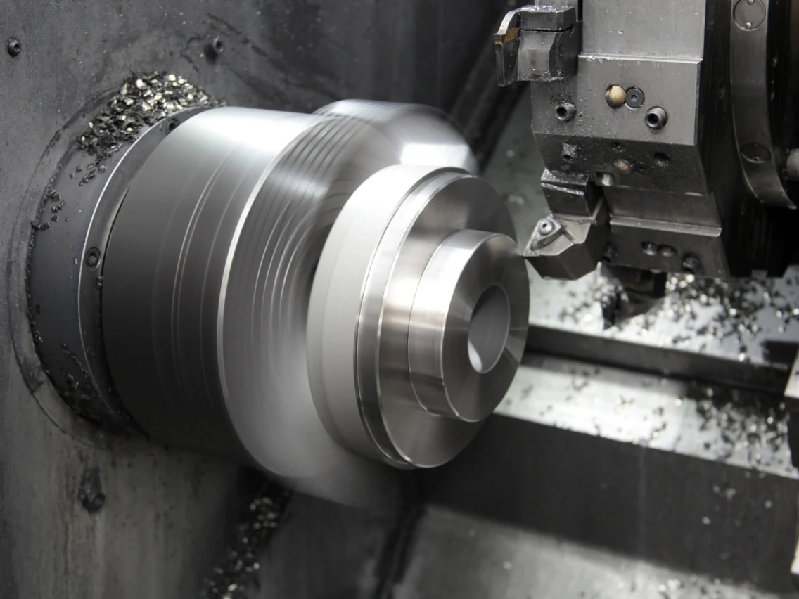
Turning is applied where the drawing includes concentric bosses, bores or rotational interfaces. Establishing these features from a controlled setup supports consistent relationships between rotational geometry and the plate datums used downstream.
Wire EDM
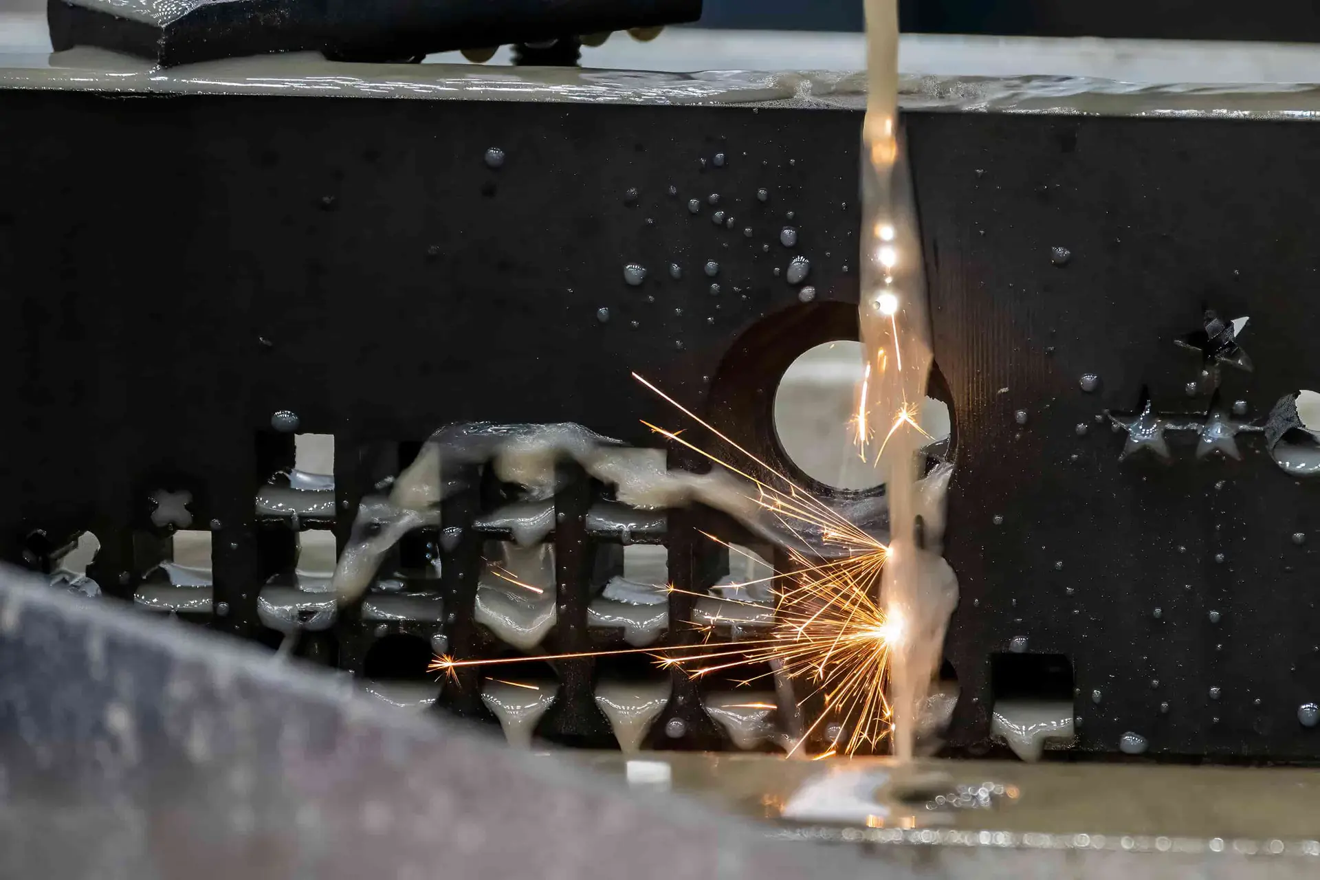
Wire EDM produces narrow slots, sharp internal contours and hardened-profile features where milling-tool access is restricted. Wire path, start-hole location and allowable corner conditions should be defined against functional geometry and inspection requirements.
Sinker EDM
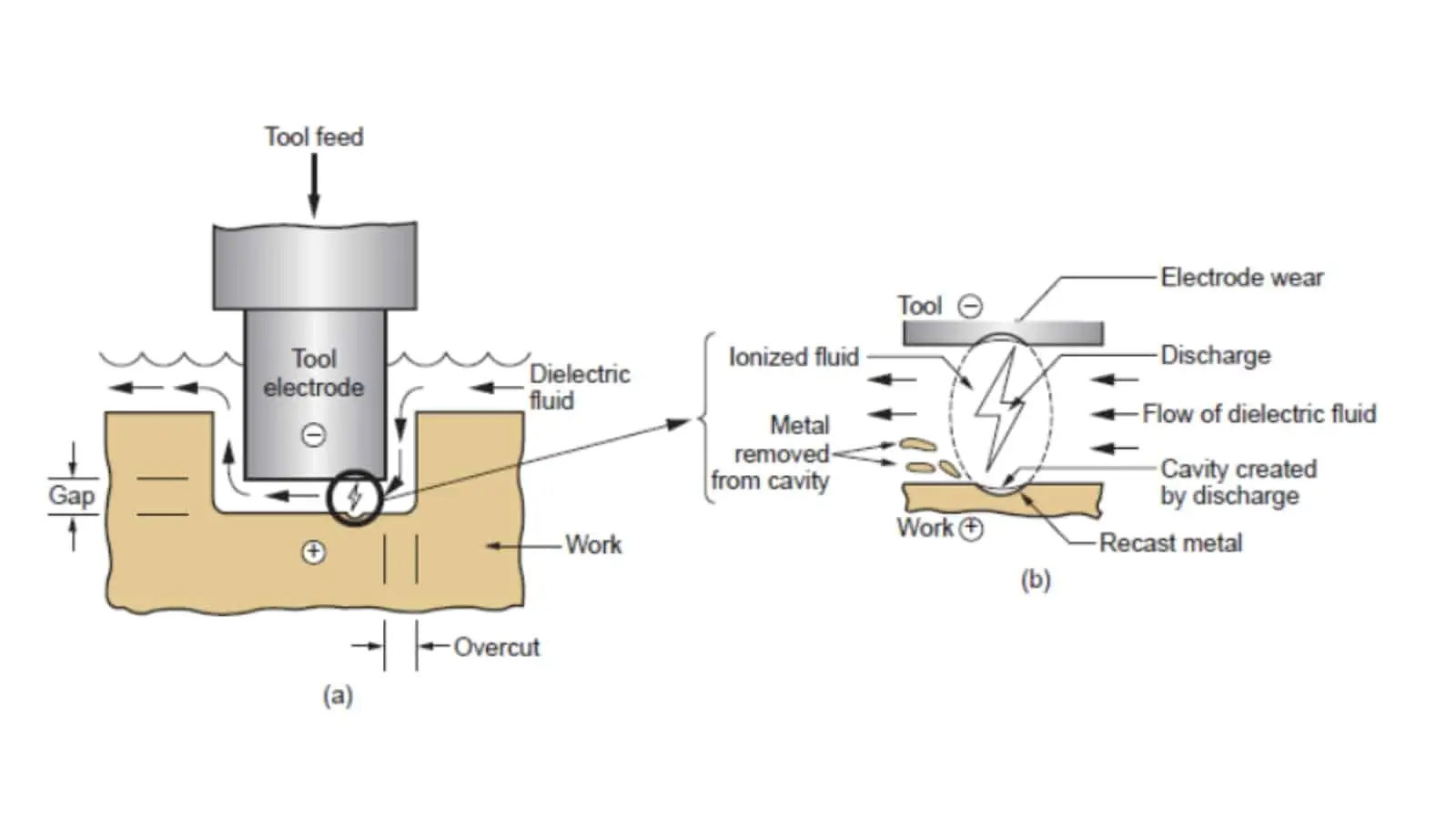
Sinker EDM addresses deep cavities, inaccessible internal forms and localized details that cannot be reached reliably with conventional cutting tools. Electrode design, spark allowance and subsequent finishing requirements are planned from the drawing.
Precision Grinding
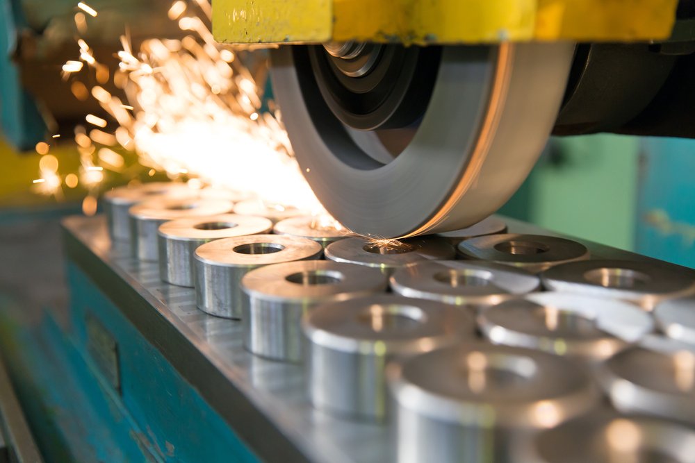
Precision grinding refines selected faces, thickness relationships and critical locating surfaces after the applicable machining or heat-treatment sequence. Grinding stock, datum strategy and required surface condition are confirmed before the final process route is released.
Fitting and Inspection
Fitting and inspection confirm the relationship of cam plate features to mating components, critical dimensions and specified datums. The inspection method, reporting needs and revision status are aligned with the approved drawing before delivery.
CNC Machined Cam Plates: Functional Options

Locating Features
Dowel holes, datum pads, locating bores and keyed features can support repeatable orientation during assembly. Their position, fit and inspection method should be defined against the mating component and datum scheme.
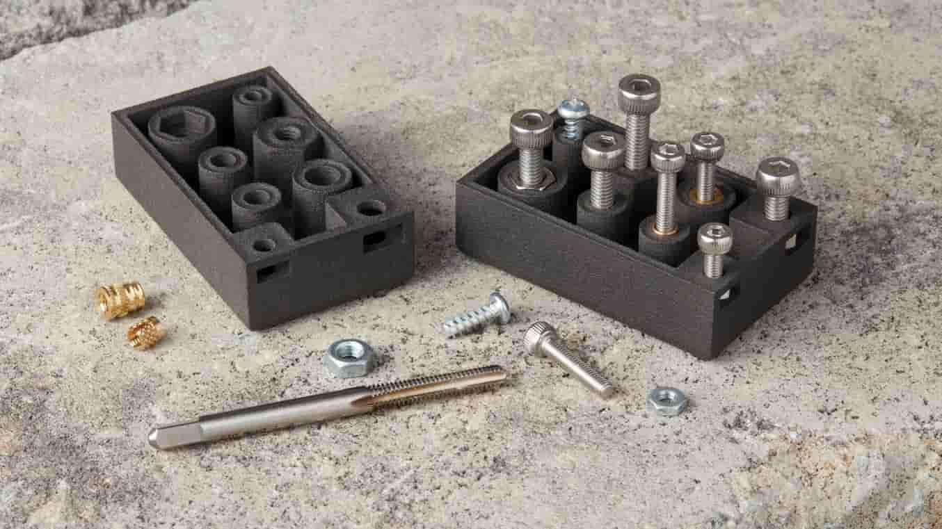
Threaded Inserts
Threaded inserts may be considered where repeated assembly, material choice or thread durability requires them. SUUXIANG reviews installation access, pull-out risk, thread specification and any post-installation inspection requirements before production.
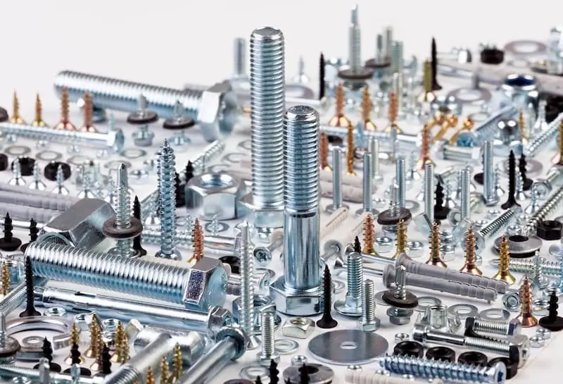
Assembly Fasteners
Specified screws, pins, plugs or retention hardware can be coordinated with the cam plate when supplied as part of the drawing package. Clarify grade, finish, torque-sensitive interfaces and responsibility for assembly or packaging.
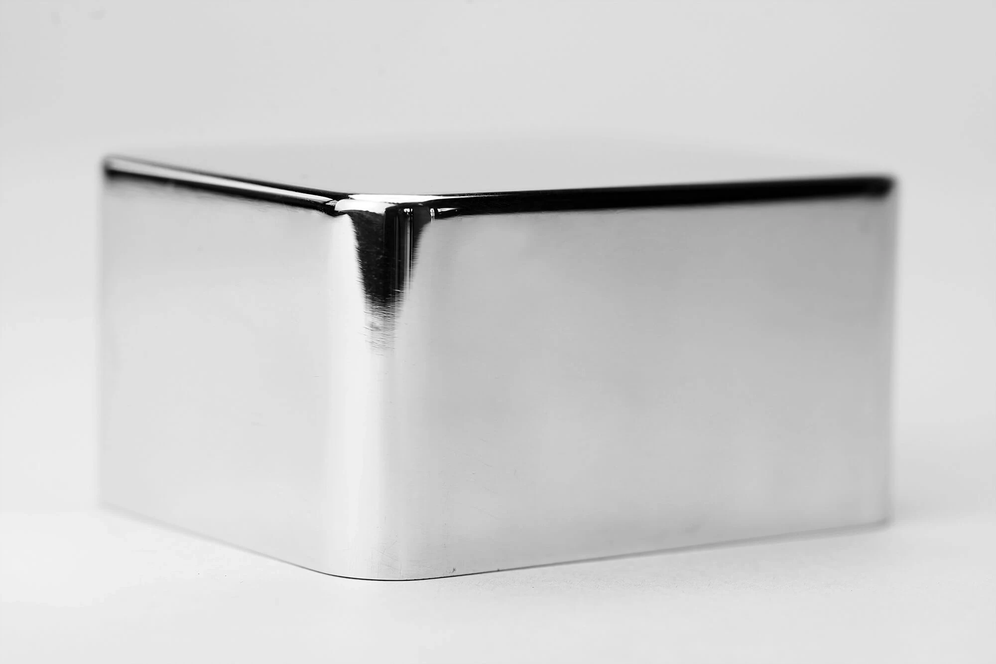
Surface Treatments
Anodizing, plating, passivation or other specified treatments can be evaluated for corrosion resistance, wear behavior or appearance. Masking requirements, dimensional buildup, critical fits and post-treatment inspection need confirmation before release.
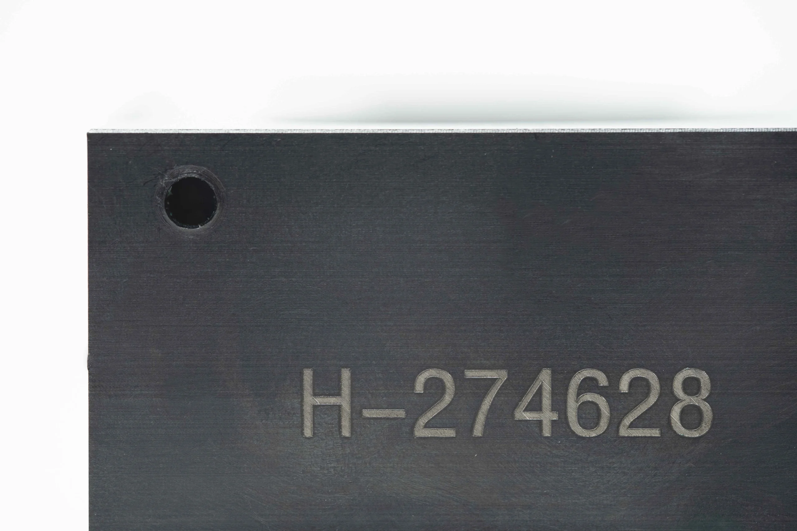
Part Marking
Part numbers, revision identifiers, orientation marks or traceability codes can be applied where the application permits. Define marking method, location, legibility requirement and whether the mark must remain visible after assembly or finishing.

Protective Labels
Labels and packaging identifiers can help distinguish revisions, inspection status or assembly sets during shipment and receiving. Provide the required text, label location, barcode format and any handling constraints with the RFQ.
About SUUXIANG Precision Manufacturing
SUUXIANG is the sole public-facing brand of Dongguan SuuXiang Precision Mold Co., Ltd., founded by XiaoCheng Huang in 2010 and based at the 2nd Floor of Sanhe Industrial Park, Chang’an Town, Dongguan, Guangdong, China. We help global teams translate drawings and specifications into inspected CNC-machined parts, precision mold components, connector tooling, and CNC machined cam plates.
Our practical manufacturing scope combines CNC milling and turning, multi-axis machining, EDM, precision grinding, fitting, and inspection. Each project is planned around the drawing, material requirement, quantity, critical dimensions, datum strategy, surface needs, and any relevant heat-treatment or reporting expectations.
What differentiates SUUXIANG is disciplined project control before production begins. We use DFM discussion to identify tool access, machining allowance, electrode or wire path needs, inspection methods, and revision requirements, then keep manufacturing and delivery information visible through the agreed workflow.

How We Plan CNC Machined Cam Plates
DFM and Datum Review
Before quoting CNC machined cam plates, SUUXIANG reviews the drawing, model, functional interfaces, datums and critical dimensions. The discussion identifies tolerance-stack risks, tool access, machining allowance and the evidence needed to define a practical process route.
- Confirm drawing revision and 3D-model alignment
- Identify critical dimensions and datum relationships
- Review pockets, holes, edges and inaccessible features
- Clarify material, heat treatment and surface requirements

CNC and EDM Strategy
Cam plate geometry may call for CNC milling, multi-axis positioning, wire EDM or sinker EDM. SUUXIANG plans the sequence around feature geometry, corner conditions, electrode requirements and wire paths, while keeping clamping access and downstream finishing in view.
- Select machining routes by feature geometry
- Assess internal corners and EDM requirements
- Plan setups around stable workholding access
- Coordinate machining stock for later finishing
Grinding and Functional Fitting
Where mating faces, guiding features or controlled flatness require refinement, the process plan can reserve stock for precision grinding and fitting. SUUXIANG evaluates these operations against the drawing’s functional requirements rather than treating every surface as a grinding requirement.
- Define grinding stock before earlier operations
- Review mating faces and locating features
- Separate functional surfaces from noncritical areas
- Consider heat-treatment sequence and distortion risk
Inspection and Revision Control
Inspection planning begins with the drawing’s critical characteristics, datums, and reporting expectations. For CNC machined cam plates, SUUXIANG aligns measurement methods, revision status, and final documentation with the agreed order requirements before delivery is coordinated.
- Agree inspection priorities and reporting needs
- Link measurements to specified datums
- Maintain visible drawing-revision control
- Match final records to the inspection plan
CNC Machined Cam Plates: A Drawing-First Sourcing Comparison
Compare a documented engineering workflow with less-documented quote-led sourcing approaches before committing a drawing to production.
← Swipe left or right to view →
CNC Machined Cam Plates: From RFQ Review to Controlled Delivery
A drawing-led workflow keeps process decisions, critical dimensions, inspection requirements and delivery coordination visible before production begins.
Review Drawing Requirements
We review drawings, models, material, quantity, datums, critical dimensions, surface requirements, inspection needs, application context and requested delivery date.
Plan Process Route
The team evaluates DFM, machining access, workholding, tolerance stack, heat-treatment sequence, EDM needs, grinding stock and practical inspection methods before quotation.
Machine Core Features
CNC milling, turning or multi-axis machining establishes plate profiles, bores, pockets and reference features according to the approved drawing revision.
Apply EDM and Grinding
Where geometry or finish requires it, wire EDM, sinker EDM and precision grinding are planned around electrode strategy, wire paths and controlled allowances.
Inspect, Pack, and Coordinate Delivery
Finished CNC machined cam plates are checked against the agreed inspection plan, documented as required, protected for shipment and coordinated with order delivery details.
Start Your CNC Machined Cam Plates Project
Move from drawing review to controlled production with clear requirements, documented decisions and inspection aligned to critical features.
Submit Your Drawing Package
Provide 2D drawings, 3D models when available, material, quantity, delivery target, critical dimensions, surface requirements and inspection or application context.
Review Manufacturing Requirements
Align on datum strategy, tolerance stack, tool access, machining allowance, EDM or grinding needs, heat-treatment sequence and inspection approach before quotation.
Approve the Production Plan
Review the proposed process route, commercial scope and revision details; approve samples or first-article checkpoints when your project requires them.
Track Production and Delivery
SUUXIANG coordinates machining, EDM, grinding, fitting and inspection against the approved plan, keeping revision status and final documentation visible through delivery.
Customer Evidence for CNC Machined Cam Plates
CNC Machined Cam Plates: Approved Customer Outcomes
Customer testimonial pending: publish only after written permission, verified project scope, and confirmation of measurable outcomes such as quantity, dimensional results, inspection evidence, and delivery performance.
Case-study slot reserved for a verified CNC machined cam plates project. Include the approved drawing revision, production quantity, inspection method, and documented outcome before assigning a customer quote or rating.
Customer outcome pending verification. This slot should document a specific, permissioned result from DFM review through inspection, with attributable figures confirmed by both SUUXIANG and the customer.
Buyer’s Guide to CNC Machined Cam Plates
Prepare the drawing, quality requirements, and delivery details needed for a disciplined quotation review.
What is the MOQ for cnc machined cam plates?
Can I order a prototype sample of cnc machined cam plates before production?
What lead time should I expect for custom cnc machined cam plates?
What files should I send for a cam plate quotation?
Can you provide inspection reports for cnc machined cam plates?
How do you protect drawings and intellectual property?
What payment and shipping information is needed before ordering?
What information helps avoid quotation changes after the RFQ?
The Complete Buyer’s Guide to cnc machined cam plates
Use this decision framework to specify cnc machined cam plates, compare supplier capabilities and inspection controls, understand cost drivers, and avoid drawing, material, tolerance, and validation mistakes that disrupt tooling and production programs.
1. What Are cnc machined cam plates?
Two functional faces often define a cnc machined cam plate: a guided profile that converts actuator or slide travel into controlled motion, and a locating face that repeats the position of its mating component. In mold tooling, stamping dies, connector tooling, and motion-control assemblies, the plate may carry side loads while preserving the geometry of a slide, cam, punch, or insert.
A 2D drawing and 3D model normally define the part being sourced rather than a generic flat plate. Its controlled features commonly include the outside profile, mounting and dowel holes, slots, relief pockets, datum surfaces, and wear interfaces that contact gibs, followers, or mating plates.
Unlike automotive engine cam plates, this is a drawing-defined tooling component whose value lies in repeatable guided movement and stable location under the intended assembly load. Buyers should identify the functional datums, mating parts, motion direction, contact surfaces, and critical dimensions before selecting a machining route.
2. How cnc machined cam plates Evolved
3-axis CNC milling replaced much of the manual layout, indicating and hand-blending once used to make die and mold cam components. Digital toolpaths let the supplier repeat defined geometry from the released model, while a datum scheme ties hole patterns, pockets and working faces to the same drawing reference.
4-axis and 5-axis access can reduce refixturing where angled faces, compound pockets or side features are present. That does not eliminate process planning: tool reach, clamping distortion, cutter deflection and finishing allowances still need review against the critical dimensions.
2D drawings, 3D models and revision-controlled inspection records changed what procurement teams should request for cnc machined cam plates. Instead of accepting a sample judged mainly by fit, buyers can require identified datums, measurement methods, material and heat-treatment requirements, deviation disposition and traceable revision status—particularly when iterative or low-volume releases must remain interchangeable.
3. Types of cnc machined cam plates
Six functional families help define the architecture of cnc machined cam plates before material or finish is selected. Classify the plate by how it moves, supports, times, or survives contact within the mechanism.
Slide and Dwell Plates
Slide cam plates convert guided travel into a defined lateral motion; angled faces, pockets, and datum-controlled mounting holes are common. Dwell or guide plates maintain position through part of the stroke, so stroke length, engagement, clearance, and guide alignment require specification.
Support and Timing Plates
Mounting and backing plates provide a rigid interface behind an actuator, slide, or insert; flatness, hole location, and bearing-area support govern fit. Index or timing plates establish repeatable angular or linear positions through slots, detents, or profiled tracks; specify the reference datum and permissible positional error.
Wear and Custom Plates
Wear-interface plates carry sliding contact at replaceable surfaces; contact geometry, lubrication provision, fastener access, and replacement clearance matter. Custom mechanism plates combine cam paths, reliefs, and interfaces for a specific sequence; define motion envelopes, mating parts, critical dimensions, and inspection points before choosing steel, coating, or finish.
4. Materials for cnc machined cam plates
Material selection for cnc machined cam plates starts with contact load, mounting stiffness, exposure, and planned service life. Specify the plate separately from replaceable wear elements when their functions differ.
| Material Family | Best Use | Tradeoff | Supplier Question |
|---|---|---|---|
| 6061-T6 aluminum | Prototype, light support | Low wear resistance | What load and contact path? |
| 4140 alloy steel | Rigid support plate | Heat-treatment distortion | Required hardness and datum? |
| Stainless steel | Corrosive environment | Galling risk | What mating material? |
| Tool steel | Hardened sliding track | Grinding required | What lifecycle and finish? |
| Bronze insert | Replaceable wear interface | Retention complexity | How is insert serviced? |
Structural Plate Choices
6061-T6 aluminum reduces mass and machines readily, but suits moderate structural duty rather than severe sliding wear.
4140 alloy steel adds stiffness and can be heat treated; define hardness, distortion limits, and finish stock.
Wear And Corrosion Strategy
Tool steel suits hardened tracks and high-cycle contact, provided heat-treatment sequence and grinding allowance are agreed.
316 stainless improves corrosion resistance but is not a default wear solution; assess galling against the mating part.
Replaceable Bearing Elements
Bronze inserts or bearing pads can protect a structural plate in sliding contact. Confirm retention method, lubricant, clearance, and replacement access.
5. Custom Features for cnc machined cam plates
A 2D drawing and 3D model should define customization for function: motion path, locating, clearance, assembly, and service identification. For cnc machined cam plates, appearance is secondary to datum-controlled geometry.
| Feature | Functional Effect | Cost And Inspection Impact |
|---|---|---|
| Angled profile | Controls motion or clearance | Multi-axis access and datum verification |
| Dowel bore | Sets repeatable location | Positional inspection against datums |
| Surface finish | Changes wear or corrosion behavior | Masking or post-finish sizing may apply |
Geometry And Mating Features
Complex profiles, angled faces, pockets, reliefs, threaded holes, dowel locations, and counterbores should reference functional datums.
Mating inserts require their interface dimensions, fastener engagement, and assembly sequence to be specified before machining.
Finish And Masking Strategy
Anodizing, black oxide, plating, passivation, grinding, or wear coatings should be called out only when corrosion, friction, conductivity, or appearance requires them.
Critical fits, threads, bearing faces, and dowel bores may need masking or post-finish machining because finish buildup changes dimensions.
Inspection Consequences
Engraved identifiers support revision control and traceability but should avoid critical sealing or sliding surfaces.
Every custom feature adds setup, tooling, inspection access, or reporting requirements; identify critical dimensions and measurement methods in the RFQ.
6. Quality Elements in Cam Plate Construction
Two requirements beyond nominal size are a functional datum scheme and an inspection plan tied to assembly interfaces. Require CTQ callouts for bearing, slide, fastener, and mating features before release.
Datum And Stack Control
Datum A should be the stable mounting face; B and C should constrain clocking and lateral position. The drawing should identify functional faces rather than merely convenient machining references.
Each critical feature needs a tolerance-stack analysis from its datum references to the mating component. Control flatness, parallelism, perpendicularity, and true position where assembly motion depends on them.
Verification Evidence
Three inspection methods cover different risks: CMM or height-gauge checks for locations, pin gauges for bores, and thread gauges for internal threads.
One first-article report should state datum setup, measured results, gage identity, and drawing revision. Material certificates and finish verification should match the purchase order.
Edges, Heat, And Wear
Two edge conditions often cause hidden assembly failures: burrs in precision bores and unspecified edge breaks around sliding paths. Define acceptable deburring and protect datum edges.
Heat treatment can move a plate after machining; specify the sequence, grinding stock, and final verification. Surface finish, contact pressure, lubrication, and counterface material jointly govern sliding-surface wear.
7. Choosing a cnc machined cam plates Supplier
Three review points reveal whether a supplier can make cnc machined cam plates repeatably: drawing interpretation, process control, and evidence returned with the parts. Evaluate the proposed route before comparing quoted price.
Test The DFM Review
1 complete review should identify CTQ dimensions, datums, tool access, fixture locations, EDM needs, and grinding allowance. Ask for marked-up drawings and the assumptions behind each proposed change.
- Which dimensions drive function or mating?
- How will the plate be clamped and re-datumed?
- What risks remain after heat treatment?
Request Process Evidence
2 evidence sets matter: material traceability and an inspection plan linked to drawing revision. Request material documentation options, first-article records, measurement methods, and sample-approval criteria before release.
- Material and heat-treatment records, if specified
- Ballooned drawing and inspection report
- Photos of fixture and protective packaging
Audit Project Control
3 controls should be visible in communication: revision confirmation, milestone dates, deviation approval, and shipment status. Suppliers experienced in mold or connector tooling should explain datum-sensitive features rather than promise unsupported capability.
- Who approves a drawing revision?
- When are risks and delays reported?
- How are parts protected against transit damage?
8. Common cnc machined cam plates Sourcing Mistakes
Two drawing omissions can consume more time than the milling cycle: an unclear locating scheme and an undefined functional requirement. Prevent them during drawing review, before material is released.
Unclear Datums And Functions
One unchecked datum scheme lets inspection and assembly reference different surfaces. Define primary, secondary, and tertiary datums, then flag profile, position, and motion-critical faces as CTQ features.
Price-Only Material Decisions
One lowest-cost material choice can change wear, distortion, corrosion response, and heat-treatment behavior. Specify the material grade, required condition, hardness range, and approved substitution process in the RFQ.
Holes And Stack-Ups
Every hole does not perform the same job: clearance, dowel location, tapped retention, and reamed guidance need different controls. Identify hole function and provide mating-part dimensions, fastener data, and assembly stack-up.
Sample Approval And Revisions
One cosmetically acceptable sample can still bind under load or miss its travel position. Approve parts against a functional check, then release revisions through a controlled drawing number, revision level, and written change notice.
9. Steps to Launch a Cam Plate Project
One complete RFQ gives SUUXIANG the basis to review function, manufacturability, inspection scope, and delivery risk before quoting cnc machined cam plates. The first build should prove the controlled drawing revision, not merely produce a sample.
Define Function And Loads
Two inputs set the review direction: the cam plate’s application and its expected load path. State mating parts, travel, contact zones, cycle conditions, and any clearance or wear concern.
One datum scheme should locate every critical feature. Flag profile, hole position, flatness, parallelism, and surface requirements that affect assembly.
Submit A Controlled Package
Three controlled items prevent avoidable rework: native model, dimensioned 2D drawing, and revision status. Include the BOM, quantity, material callout, heat treatment, finish, target date, and required reports.
One DFM review should resolve tool access, workholding, machining allowance, EDM or grinding needs, and measurable datums before release.
Approve And Scale Production
One prototype or first article should be approved against the agreed inspection plan before low-volume production. Review actual critical-dimension results, finish, fit with mating components, and any deviation disposition.
Each subsequent order should reference the released revision, approved changes, inspection records, and packaging requirements. This preserves traceability as prototype quantities transition to repeat low-volume builds.
10. cnc machined cam plates Pricing and Cost
2 quotation stages should separate one-time engineering from repeatable production: drawing review, datum confirmation, CAM programming, fixturing, and first-article inspection are largely setup-driven. Material grade and condition, stock thickness, part envelope, tool access, pockets, angled faces, tight tolerances, finishing, heat treatment, and reporting then determine the process route.
1 complete RFQ reduces avoidable cost when it defines the 2D drawing, 3D model, quantity, material and hardness, critical dimensions, surface requirements, inspection method, revision, and required date. Consolidating compatible parts, standardizing stock, relaxing nonfunctional tolerances, and avoiding late revisions can lower total program cost without weakening functional requirements.
| Quantity tier | Relative unit-cost trend | Setup-cost impact | Typical lead-time drivers |
|---|---|---|---|
| 1–5 pieces | Highest | Dominant share | Programming, fixturing, material availability, first-article inspection |
| 6–25 pieces | Declining | Spread across parts | Repeat setups, machining time, EDM or grinding needs |
| 26–100 pieces | Lower | Reduced per unit | Cycle-time control, inspection sampling, finishing coordination |
| 100+ pieces | Project-specific | Amortized when repeatable | Fixture strategy, capacity planning, batch inspection, delivery schedule |
Upload Your CNC Machined Cam Plates Drawing
Include material, heat treatment, quantity, critical dimensions, inspection requirements, and target delivery date for a disciplined DFM and quotation review.