
Engineering guide
Designing CNC Parts with Multiple Setups
Parts that require machining from several orientations should be designed around relationships, not just individual features. This guide provides a review method for mapping critical geometry, selecting workable references, separating locating from clamping, planning stock and sequence, and documenting inspection and RFQ decisions that need engineering agreement.
On this page
- Map Functional Relationships First
- Identify Practical Tool Approaches
- Choose References That Survive Repositioning
- Separate Locating From Clamping
- Plan Sequence And Remaining Stock
- Compare Indexing And Separate Setups
- Work Through An Illustrative Bracket
- Build Inspection Into The Handoff
- Prepare A Review-Ready RFQ
- References and further reading
Map Functional Relationships First
Begin with the part’s functional relationships rather than with its most visually prominent face. Identify which holes must align with a pocket, which mounting face must relate to a bearing seat, which profile governs clearance, and which threaded feature is only a fastening interface. A useful review question is: if this part is rotated during manufacture, which relationships must remain most controlled when it returns to assembly?
Mark each relationship as assembly-critical, interface-important, or noncritical. This classification helps distinguish a feature that merely needs to exist from one whose location relative to another feature determines performance. For example, a cover plate may have cosmetic outer contours, clearance holes, and a sealing land. The sealing land’s relation to its mating face deserves a different setup discussion from the outer contour.
Then draw a simple relationship map beside the CAD model or drawing. Connect features that share a functional requirement, and note the face or axis from which each relationship should be understood. The map is not a replacement for tolerancing; it is a planning aid that reveals when features on opposing faces should be considered together and when a later setup could introduce an avoidable dependency.
- Ask which feature relationships affect fit, sealing, alignment, motion, or load transfer.
- Separate feature importance from feature visibility.
- Flag relationships that cross a likely repositioning boundary for manufacturing review.
Identify Practical Tool Approaches
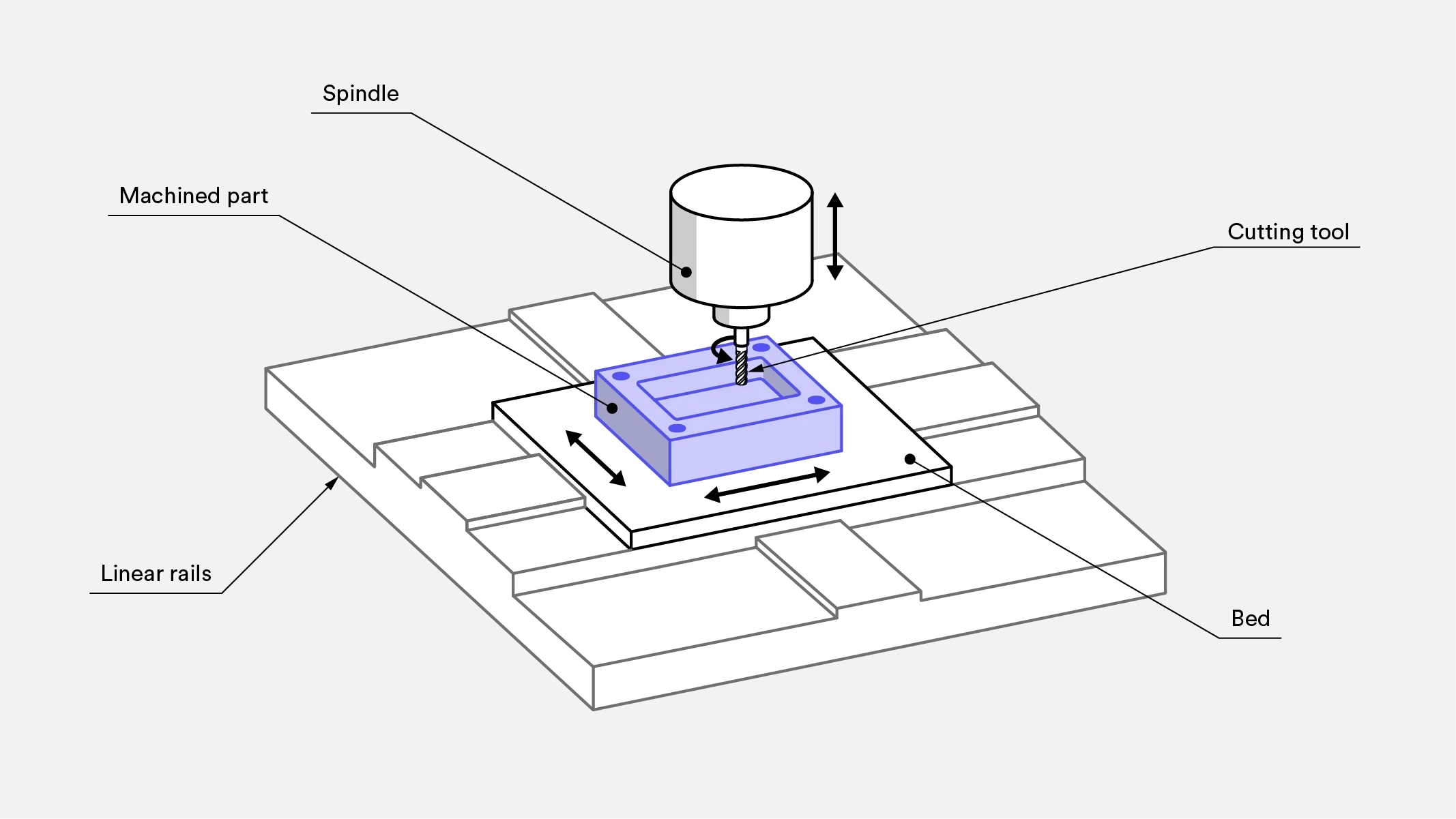
For each feature, consider how a cutter, drill, thread-making tool, or measuring device would approach it. A feature may look straightforward in a model yet become difficult when a neighboring wall blocks access, a deep recess limits tool reach, or a chamfer changes the usable entry condition. Record the intended approach direction for every critical feature before assuming that one orientation can serve all of them.
Approach review should include the surrounding geometry, not only the target dimension. Ask whether a cutter can enter and leave without damaging an adjacent surface, whether a hole has a clear starting surface, and whether an internal corner is compatible with a practical tool shape. If a tool cannot reach a feature in the desired orientation, the design may need a separate setup, a geometry change, or an explicitly agreed alternative process.
Threaded and blind drilled features deserve their own questions. Define the required thread, usable depth, and any bottom condition separately from the overall drilled depth, because these communicate different intent. The appropriate thread-making method and the suitability of the hole bottom depend on material, access, geometry, and the agreed process; they should not be inferred from a generic CAD symbol alone.
- List an approach direction for critical holes, pockets, threads, and side features.
- Check clearance for both cutting and measurement.
- Request engineering agreement when thread depth, blind-hole bottom form, or access is not fully defined.
Related technical reading: [3] Threading application guide
Choose References That Survive Repositioning
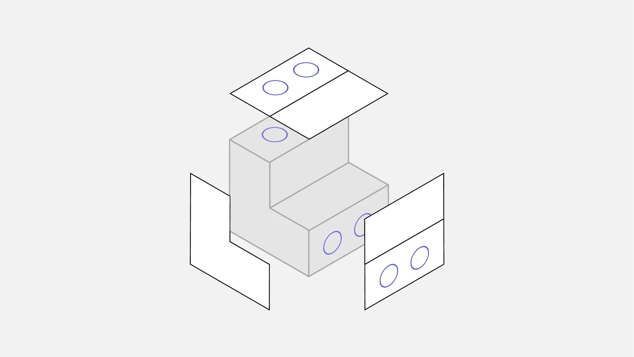
A reference strategy should describe how the part is understood at every stage, including after it is turned or indexed. Start with a stable functional surface or feature that is meaningful to assembly. Then decide which secondary features establish orientation and which feature prevents unintended shift. A reference chosen only because it is easy to see in the first operation may become unusable after material is removed or a fixture covers it.
Prefer surfaces that can be machined, accessed, and protected through the planned sequence. A rough exterior face can be useful early, but it may not be appropriate as the basis for a final relationship if its condition changes later. Conversely, finishing a reference too early may expose it to clamp marks or handling damage. The right choice depends on material behavior, stock form, geometry, finish requirements, and fixture concept.
Document the distinction between design datums and manufacturing references. They may coincide, but they do not automatically do so. When they differ, the drawing and RFQ should make the functional intent clear enough for engineering to evaluate the translation. This prevents a later inspection result from being judged against an assumed reference that was never agreed during process planning.
- Identify a primary reference, orientation reference, and shift-control feature for each stage.
- Verify that later machining does not remove or compromise a reused reference.
- Make any difference between design datum and process reference reviewable.
Related technical reading: [1] Locating and clamping principles
Separate Locating From Clamping
Locating and clamping solve different problems. Locating establishes where the workpiece sits relative to the machining reference; clamping holds it against those supports while cutting occurs. Treating a clamp as though it were a precise location can make a process sensitive to contact variation, burrs, surface condition, or changing clamp force. In the design review, ask what physically establishes position before asking how the part is held down.
Consider the contact surfaces available at each setup. They should provide stable support without obstructing critical machining or inspection areas. Thin walls, curved faces, freshly finished surfaces, and narrow edges may need special consideration because their suitability depends on geometry, material, clamping direction, and required finish. If a surface is both an important interface and the only obvious clamp area, raise that conflict early.
The following comparison can guide a fixture conversation without prescribing a particular fixture. It is especially useful when the CAD model offers many flat faces but only a few that remain accessible after earlier operations. The manufacturing plan should be confirmed by engineering when the selected contacts could affect a critical relationship or surface condition.
| Review item | Locating question | Clamping question | Decision implication |
|---|---|---|---|
| Finished mounting face | Can it establish a repeatable orientation without being harmed? | Can force be applied elsewhere while maintaining support contact? | If not, preserve another reference or revise the sequence. |
| Rough stock edge | Is its variation acceptable for an early-stage reference? | Will holding it distort or shift the part? | Use only where its condition matches the stage’s purpose. |
| Thin feature | Can it resist positional contact without deflection? | Will holding force alter shape or leave marks? | Seek an alternative support, temporary stock, or agreed process. |
| Internal pocket | Is it accessible and stable enough to reference? | Does clamping block the feature or later measurement? | Confirm access before making it a process reference. |
Related technical reading: [1] Locating and clamping principles
Plan Sequence And Remaining Stock
A multi-setup part benefits from a written sequence that explains why each operation occurs when it does. Begin by preparing faces or features needed to establish later references, then create geometry that improves secure holding or orientation, and reserve features vulnerable to handling or clamping until a suitable stage. The sequence should follow functional priorities and accessibility, not simply the order in which features were modeled.
Remaining stock is a design and planning issue, not an afterthought. Material may be intentionally retained to support a thin area, create a clamping region, or protect a final surface until a later orientation. Before releasing the design, ask which regions must remain untouched at each stage and which final features cannot be completed until temporary support is no longer needed. This requires agreement when it changes edge condition, accessible geometry, or inspection timing.
A practical handoff is a staged feature list: early reference features, intermediate features that create access or holding, and final features whose relationships require the most deliberate control. Include special finish areas and surfaces that must remain free of fixture contact. The list makes it easier for engineering to challenge an impractical sequence before the drawing is interpreted as a fixed routing.
- State which surfaces may be contacted, machined early, or left until final stages.
- Protect function-critical surfaces from unnecessary intermediate exposure.
- Ask whether temporary material is needed for support, and record the resulting design constraint.
Related technical reading: [1] Locating and clamping principles
Compare Indexing And Separate Setups
An indexed multi-axis process and separate setups can both be suitable ways to reach features on several orientations. The useful comparison is not a claim that one is inherently better; it is whether the method supports the required relationships, access, holding strategy, material condition, and inspection plan. A part with related faces around a common reference may invite an indexing discussion, while a part needing substantially different support conditions may require separate holding arrangements.
Do not decide from the number of visible sides alone. Ask whether all critical features can be reached from the proposed orientations, whether a single holding condition conflicts with any delicate surface, and whether a later operation needs a newly created reference. Material, overall geometry, feature depth, wall stiffness, finish, and order requirements can all change the answer. Engineering should confirm the process route rather than treating a model orientation as a manufacturing instruction.
Use the comparison below to frame the RFQ conversation. It deliberately avoids promises about capability, cycle time, accuracy, or commercial outcome. The selected route remains subject to drawing requirements and the manufacturer’s engineering assessment.
| Decision factor | Indexed multi-axis discussion | Separate-setup discussion | Question for engineering agreement |
|---|---|---|---|
| Related features around the part | Consider whether shared holding supports their intended relationship. | Consider whether each orientation needs its own stable reference. | Which feature relationships must be preserved most directly? |
| Surface protection | Review whether the same holding condition leaves sensitive areas clear. | Review whether each re-clamp introduces a surface-contact conflict. | Which surfaces cannot tolerate fixture contact or later machining? |
| Access | Review tool paths from indexed orientations. | Review whether an alternate face provides clearer tool and measurement access. | Can every critical feature be machined and checked from the proposed route? |
| Part stiffness | Review support through all indexed positions. | Review whether changing support is necessary as material is removed. | At which stage is the part least able to resist machining and holding forces? |
Related technical reading: [1] Locating and clamping principles
Work Through An Illustrative Bracket
A possible planning discussion begins with preparing a stable reference face and an orientation feature, then assessing whether the web can remain supported while the recessed area and side holes are produced. If the web becomes slender after pocketing, retaining support material or changing the sequence may be worth engineering review. The final threaded feature must be checked for approach clearance and for the separately defined usable thread and bottom condition.
This example shows why a feature-by-feature checklist is insufficient. The question is not merely whether each feature can be made; it is whether the bracket can be held, referenced, reached, and inspected without undermining the relationships that matter. Actual bracket decisions depend on the released drawing, material, stock condition, and agreed manufacturing process.
- Map the base, side-hole pattern, recess, and threaded axis according to their assembly role.
- Review web support before removing nearby material.
Related technical reading: [3] Threading application guide
Build Inspection Into The Handoff
Inspection planning should start while references and sequence are still being discussed. For each critical relationship, state the feature being evaluated, the governing design reference, the condition in which it is checked, and any access concern. A dimension that is visible in the drawing but blocked by a fixture, hidden within a recess, or dependent on an unfinished reference needs a different inspection plan from an exposed final surface.
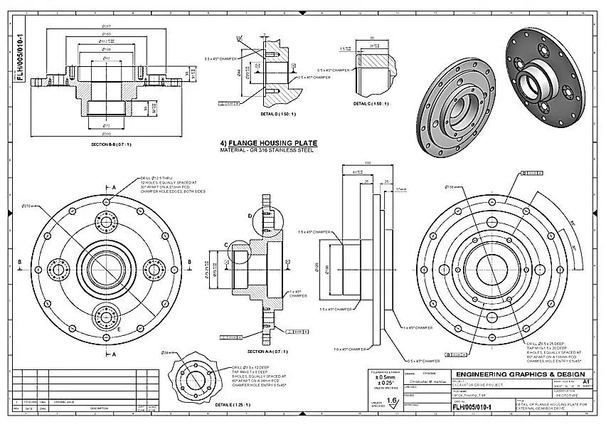
The drawing should communicate threads, tolerances, finishes, and other information that CAD geometry alone does not fully express. Clearly identify critical features and design authority so manufacturing and inspection teams know which requirements require particular attention. Do not leave a visually obvious edge, surface, or hole to carry unstated functional meaning; spell out the requirement where it matters.
In-process measurement can assist setup confirmation and process control, but it does not replace the agreed final acceptance approach. Decide whether a feature needs confirmation before a later operation removes access, and whether the completed part can be evaluated against the intended reference. The appropriate method depends on drawing requirements, geometry, and the agreed inspection plan.
- Connect every critical feature to a defined design reference and inspection condition.
- State finishes and thread information outside of implied CAD appearance.
- Identify checks that must occur before later work obscures a feature or reference.
Related technical reading: [2] How probing helps machining
Prepare A Review-Ready RFQ
A strong RFQ gives engineering enough context to test the setup strategy without pretending to dictate every manufacturing detail. Supply the current CAD model and drawing, material specification, quantity context, finish requirements, critical relationships, designated design references, thread notes, and any surfaces that must avoid contact or cosmetic damage. State which dimensions are functional priorities rather than expecting importance to be inferred from the model.
Add a short multi-setup review note. Describe features on different orientations that must relate to one another, identify areas with restricted approach or measurement access, and flag any design assumption about sequence, temporary support, or reference reuse. Ask for engineering feedback on the proposed reference logic, workholding implications, process route, thread method suitability, and inspection accessibility. These are requests for agreement, not assertions of a required machine or outcome.
Before submission, perform one final contradiction check: does a referenced surface remain available when its dependent feature is machined and inspected? Does a specified finish conflict with likely holding contact? Does a blind threaded feature state both functional thread need and relevant hole geometry? Resolving these questions early produces a concrete, traceable review method for parts with multiple setups.
- Provide both geometry and the requirements CAD does not fully communicate.
- List cross-orientation critical relationships in plain language.
- Request engineering agreement on unresolved references, access, holding, sequence, and inspection.
- Keep final acceptance requirements distinct from any in-process control discussion.
Related technical reading: [3] Threading application guide
Questions engineers ask
When should features be grouped in one setup?
Discuss grouping when the relationship between features is function-critical and they can be reached and held from a compatible reference condition. Grouping is not automatic: access, material removal, surface protection, and inspection needs may support another route. Provide the relationship intent and ask engineering to assess the workable process.
Can a drawing datum and a manufacturing reference differ?
Yes. A design datum defines how the requirement is understood, while a manufacturing reference is used to position the part during a stage. When they differ, the RFQ and drawing should make the functional reference clear so engineering can assess how the process and inspection will maintain the intended relationship.
What should be specified for a blind threaded feature?
Specify the thread requirement and its usable depth separately from the drilled-hole depth and bottom condition. The thread-making method and suitable geometry depend on material, access, toolpath needs, and the agreed process. Request engineering review rather than assuming a generic thread detail resolves those issues.
References and further reading
These resources explain related design and manufacturing principles. Project limits, acceptance criteria and process choices must be agreed against the current drawing.
Publication note: this article is general design guidance, not a material specification, a certified inspection report or a guarantee of process capability.
Turn the drawing into a clear manufacturing brief.
Share the current drawing, material, finish and inspection requirements for a project-specific discussion.