
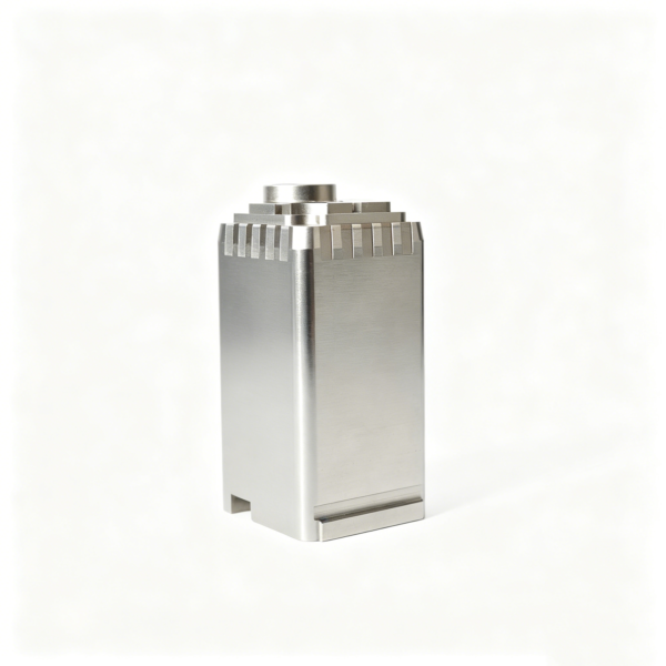
Multi-Side Precision Mold Insert for Controlled Cross-Face Relationships
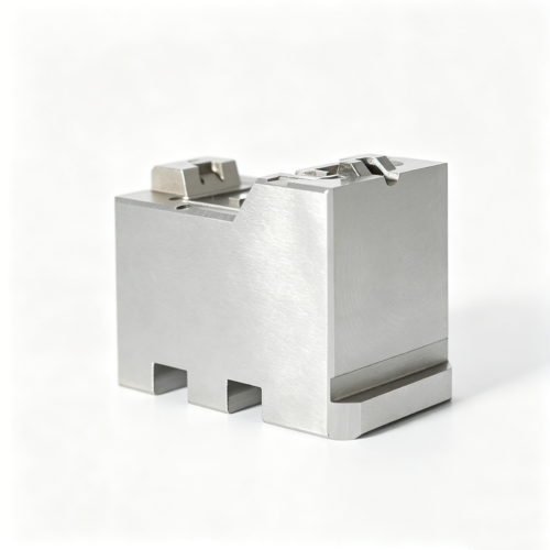
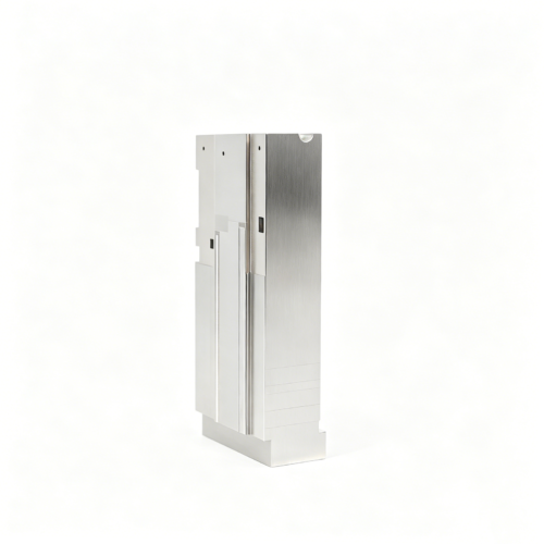
This custom insert is intended for a component whose functional features are reached from multiple setups and must remain coherent to one design datum frame. The reviewed geometry is a distinct product in original group 71902, separate from the fine-rib insert. Its photo is useful for visual orientation, while the customer drawing controls every production and inspection decision.
Distinct Geometry and RFQ Scope
The reviewed component presents a multi-side arrangement of functional and reference faces. No fixed number of sides, particular mold application or standard construction should be inferred from the image. The important manufacturing question is whether features approached from separate setups can be held to a coherent locating structure rather than becoming a collection of individually acceptable surfaces.
Cross-face relationships may include angular alignment, positional location, parallelism, perpendicularity, profile or seating behavior. The drawing should identify which of these are functional and which are merely visual. Sections and mating data are especially valuable where a face is hidden after assembly or where a tool cannot access the feature from the preferred direction.
Datum Structure and Fit Decisions
Begin the RFQ with the controlled drawing, model, revision identifier, datum frame and any parent-component information. A locating base should be identified, together with protected transfer datums that can be reproduced after re-clamping. If the drawing uses different datum schemes for machining and inspection, both should be stated clearly.
Fit decisions should define which faces seat, which features locate and which surfaces carry clearance. An isolated face can meet its own size requirement while still failing assembly because its angle or position is wrong relative to another setup. The quotation should therefore list cross-face requirements explicitly and flag missing relationships before process planning.
Conditional Multi-Setup Process
A candidate route may establish the locating base first, preserve transfer datums and sequence side work around access and stiffness. Clamping should avoid distorting thin or unsupported areas and should protect finished locating surfaces. Re-clamping can accumulate angular and positional error, so each setup requires a reproducible locating method and a reasoned order.
Final grinding or EDM may be considered only where the drawing relationship, access condition or surface requirement justifies it. These methods are not automatic requirements. Cutting strategy, stock management, stress control and heat-treatment condition must be reviewed together because a later operation can alter an earlier relationship. The final route remains conditional until engineering approves the drawing interpretation.
Access, Stiffness and Protection
Multi-side work often creates a tradeoff between tool access and component support. A setup that opens one face may reduce stiffness elsewhere. The RFQ should identify thin walls, small corner radii, deep pockets, protected seating surfaces and any areas that cannot accept clamping marks or contact pressure.
Finished datums should be protected from chips, burrs and accidental impact during later operations. Where the drawing permits, temporary stock or support may help preserve rigidity. Where it does not, the customer should approve the proposed support concept. Packaging and handling instructions should be included if the insert will be transferred between machining, inspection and assembly locations.
Inspection Across the Datum Frame
Inspection should reconstruct the design datum frame and evaluate cross-face relationships, not report isolated feature sizes alone. The plan should show how the locating base is established, how transfer datums are interpreted and how angular and positional results are related to the customer’s coordinate system.
Depending on access and drawing requirements, probing, optical measurement, comparative checking or a combination may be considered. The selected method should address hidden or partially accessible features and identify any alignment assumptions. A report should make clear whether a result is measured directly, derived from related features or compared with approved model data.
Drawing Package for a Reliable Quote
Send the latest drawing and model with revision history, material or condition requirement if known, quantity, expected repeat demand, mating component data, surface notes and inspection-document expectations. Mark critical faces and identify whether assembly evidence, dimensional reports or sectional checks are required.
Revision control is essential because a changed datum, angular requirement, access condition or seating face can change the setup order and finishing plan. The quote should reference the same revision used for engineering review. No fixed material, tolerance, coating, certification, delivery, stock or performance claim should be assumed without written confirmation.
Release Review and Engineering Questions
Before release, confirm the primary locating base, protected transfer datums, setup sequence, clamping zones, finishing allowances and inspection coordinate frame. Ask whether a face must be ground, whether EDM is acceptable for a restricted detail and whether assembly fit is verified through a mating check or dimensional report.
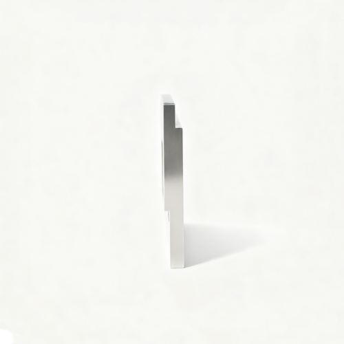
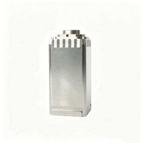
The original photo can begin a useful conversation, but it cannot define the number of sides, final function or manufacturing history. SUUXIANG’s engineering review should resolve ambiguous cross-face relationships and establish a controlled route tied to the approved drawing, model and revision.
Frequently Asked Questions
Why is re-clamping a key risk?
Each new setup can introduce angular or positional error, so transfer datums and the datum frame must be planned before side work begins.
Can every face be inspected independently?
Independent checks are insufficient when assembly depends on cross-face relationships. Inspection should reconstruct the design datum frame.
Is this insert limited to a fixed mold application?
No application should be inferred from the image. The approved drawing and intended fit define the actual scope.
Submit the Cross-Face Requirements
Send the controlled drawing, model and mating information so the multi-side insert can be reviewed for datums, setups, access and inspection.
Reviews
There are no reviews yet.