
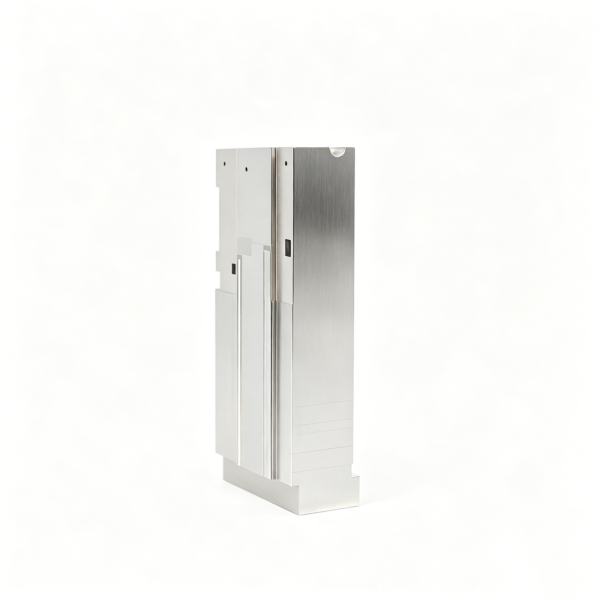
Integrated Datum-Based Connector Cavity Insert
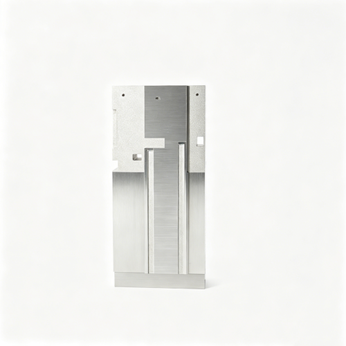
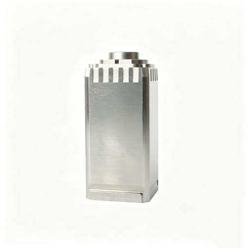
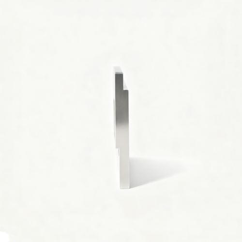
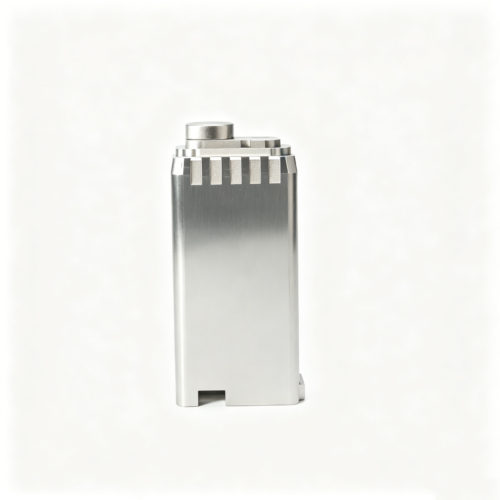
This custom connector mold cavity insert is intended for projects where cavity form, shutoff regions and the locating body must operate as one datum-based functional unit. The visually reviewed image from the same-company original product gallery 71843 is a visual reference only. It is separate geometry from SKU007 even though both share an original source page. The image does not prove dimensions, material, tolerance, molded-component identity, flash behavior or manufacturing history. The approved drawing and engineering review control every quotation decision.
Integrate the Functional Unit
The main RFQ decision is how the cavity form, shutoff regions and locating body relate to one another. These features should be reviewed as one functional unit rather than as independent shapes. Identify which faces locate the insert, which faces mate with a counterpart, and which cavity dimensions originate from those references. Fine detail may be locally correct while the cavity is shifted relative to the body or shutoff. The drawing should show the datum hierarchy, insert height, mating faces, orientation and any features that must remain available for later fitting. Do not infer a connector application from the photograph or generic market language.
Control Shutoffs and Fine Detail
Fine detail and mating shutoffs can be affected by over-polishing, EDM overcut or a misread datum. For that reason, the drawing should distinguish material-removal surfaces, protected edges, shutoff lands, transition radii and areas where polishing is limited. If an edge must remain crisp, define the allowable break or profile condition. If a transition may blend, show the permitted form rather than relying on visual judgment. Electrode access or micro-feature work may be warranted, but it remains a conditional engineering choice based on actual feature scale and access. No flash behavior is promised because it depends on the complete mating system and approved design.
Conditional Process Route
A possible route begins with datum machining and controlled roughing of the locating body and cavity region. Electrode work or micro-feature processing may be considered where the approved geometry is inaccessible by ordinary cutting. Final seating-face finishing can then be coordinated with cavity and shutoff requirements, followed by protected edge treatment based on the drawing. Cutting, grinding, EDM and finishing methods are selected only after material, access, surface criteria and inspection needs are known. The route may change when the cavity revision changes, when an insert height is adjusted, or when mating-face analysis identifies a different setup requirement.
Required Drawing and Fit Decisions
For a drawing-based RFQ, provide the latest controlled drawing, three-dimensional model when available, quantity, revision, orientation and a mating reference if one exists. Mark primary datums, locating faces, cavity centerlines, insert height, shutoff regions, mating faces, edge limits and any surfaces requiring later adjustment. State whether the insert is supplied ready for assembly, prepared for fitting or intentionally left with an approved allowance. If a feature is inaccessible, identify the intended access direction or request an engineering recommendation. A controlled image may help explain orientation, but it cannot substitute for the geometry, fit and acceptance language in the drawing package.
Inspection for Form, Position and Mating
Inspection should relate cavity position, cavity form, shutoff geometry, insert height and mating faces to the selected datums. Methods must suit the actual feature scale and may include coordinate measurement, optical or profile comparison, dimensional checks, controlled gauges or visual review against an approved reference. Fine details should be inspected from a stable setup, while seating and mating faces should be verified in the condition that represents assembly. Edge review should confirm that polishing or deburring has not changed a defined shutoff or protected feature. The inspection plan should state support, reference establishment and any limits of measurement access.
RFQ and Revision Discipline
Identify SKU SUUXIANG-SAMPLE-010 in the inquiry and state clearly that it is separate geometry from SKU007. Attach the current drawing, model, revision and any mating information. List open decisions such as electrode access, micro-feature strategy, polishing boundary, shutoff protection, seating-face sequence and inspection method. If a revision changes cavity location, insert height, mating face or fine detail, review the quotation assumptions and measurement plan together. Written approval should distinguish confirmed customer requirements from conditional process suggestions. This gives the project a traceable basis without claiming a particular molded component, process history or performance result.
Part-Specific FAQs
How is SKU010 different from SKU007?
SKU010 is a separate connector mold cavity insert whose cavity, shutoff regions and locating body are reviewed as one integrated unit. Shared gallery origin does not mean shared geometry, dimensions or quotation assumptions.
Can the image confirm a particular molded component?
No. The image supports visual orientation only. The customer drawing must define cavity form, mating relationships, shutoffs, insert height and all acceptance criteria before function is discussed.
Send the Cavity and Mating References
Share the controlled drawing, model and revision for a datum-based review of this connector mold cavity insert.
Reviews
There are no reviews yet.