
Engineering article
Inspecting Deep Bores and Recessed Features
Deep bores and recessed features often fail inspection planning before they fail machining. Their geometry can conceal surfaces, restrict probe travel, magnify alignment error, and make a simple dimension difficult to verify. This article explains how to define access, datums, method capability, reporting expectations, and exception handling so the drawing and inspection plan support the intended function.
On this page
Why Access Changes the Inspection Problem
Inspecting deep bores and recessed features is not simply a matter of reaching farther into a part. As access becomes restricted, the measurement system must manage extension deflection, limited viewing angles, reduced illumination, uncertain contact points, and alignment to the intended datums. A feature can be manufacturable while still being difficult to inspect with the evidence needed for acceptance.
The key question is therefore not whether a bore has a stated diameter and depth. It is whether the required surface, at the required location and orientation, can be reached and evaluated from a stable reference frame. When that question is answered late, teams may discover that a convenient measurement reports a result that is not equivalent to the drawing requirement.
- Treat inspection access as a design input, alongside tool access and assembly access.
- Identify whether the critical condition is at the entrance, mid-depth, bottom, or along the full bore.
- Ask whether measurement must be performed on every part, by sampling, or only during qualification.
Start With Functional Datums
Deep-feature inspection becomes more reliable when the drawing establishes datums that reflect how the part locates in service or in a controlled fixture. An external face, outside diameter, pilot feature, or mounting pattern may establish the reference frame. The inspector can then distinguish bore size from bore position, axis orientation, depth, and relationship to a concealed bottom surface.
Avoid allowing a measurement setup to create its own accidental datum scheme. For example, centering on the accessible mouth of a bore can be useful for a screening check, but it may not demonstrate the axis location relative to external mounting features. If the internal feature is functionally coaxial, perpendicular, or offset from another element, the drawing should state that relationship through an applicable standard or clearly defined engineering requirement.
- Mark primary, secondary, and tertiary datums where feature relationships matter.
- State whether the bore axis, wall, bottom, or a local land is the controlled element.
- Define partial-depth zones if different portions of the feature have different functions.
Break the Requirement Into Measurable Conditions
A single note such as “inspect deep bore” leaves too much interpretation. A useful handoff separates the conditions that affect function. Diameter may be needed at one or more axial positions. Depth may be measured from a named face to a theoretical or physical bottom. Straightness or cylindricity may matter through a specified length. Surface finish, chamfers, internal threads, cross holes, and bottom radii can each demand a different observation method.
This separation also prevents an overbroad result from being treated as proof. A plug-style check may indicate a local size condition but generally does not establish full-form geometry, axial position, or bottom profile. Conversely, a scanned internal surface can generate extensive data without answering a simple functional assembly question unless the evaluation criteria are agreed in advance.
- List each critical characteristic and its governing datum reference.
- Specify the axial locations or inspection zones for internal diameter checks.
- Clarify whether a bottom condition is a point, plane, radius transition, contour, or blend.
- State the acceptance standard when geometric tolerancing or surface requirements govern.
Choose Methods by Evidence Needed
Method selection should follow the required evidence, part geometry, material condition, production volume, and available access. Direct-contact probing can provide coordinate-based results when stylus configuration, calibration, and approach paths are appropriate. Bore gauges, air-based checks, internal micrometers, depth instruments, replicas, optical systems, and non-contact scanning may each be useful in narrower situations. No method is automatically interchangeable with another.
Long extensions can introduce bending and dynamic effects, while contact tips may be unable to approach a narrow shoulder or complex bottom form. Non-contact approaches may improve access to some regions but can be affected by line of sight, reflectivity, transparency, surface texture, or data-processing choices. The process plan should document the selected method and establish whether it evaluates the actual specified characteristic.
- Match the method to the feature zone and datum scheme, not only to nominal size.
- Request a method study when access, uncertainty, or form evaluation is central to acceptance.
- Define any approved alternative method before production reporting begins.
| Inspection need | Potential approach | Agreement needed |
|---|---|---|
| Entry or local diameter | Internal gauge or probing | Measurement depth, datum, and whether local size is sufficient |
| Axis location or orientation | Coordinate-based measurement with controlled setup | Datum alignment, probe path, and evaluated length |
| Bottom depth or profile | Depth measurement, probing, optical observation, or replica method | Reference face, bottom definition, and allowable evaluation method |
| Internal surface condition | Appropriate surface assessment or visual aid | Area assessed, access limits, and applicable requirement |
Design Geometry for Observability
Designers can often reduce inspection ambiguity without relaxing a functional requirement. A clear reference face near the feature entrance gives depth measurements a repeatable origin. A relief, accessible land, or controlled transition can help define where a diameter or profile requirement begins. Where a feature must change diameter internally, the drawing should identify the transition form and its axial position rather than relying on an implied step.
Observability must be balanced with product function, strength, sealing, cleanliness, assembly, and manufacturing constraints. An access opening added solely for measurement may not be acceptable in the final product. In those cases, a qualification strategy, dedicated fixture, sectioned sample, replica approach, or validated indirect characteristic may be considered if the engineering agreement identifies how it supports acceptance.
- Avoid hidden transitions whose location is critical but undefined.
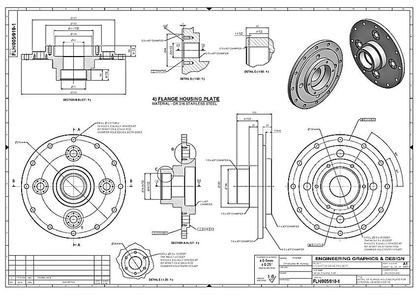
- Provide a section view for internal geometry that cannot be understood from exterior views.
- Call out controlled blends, reliefs, counterbores, and blind-bottom forms explicitly.
- Review whether inspection access conflicts with cleaning or assembly requirements.
Make the Drawing and Plan Agree
The drawing expresses product requirements; the inspection plan explains how those requirements will be evaluated. They should not contradict one another. If an internal dimension is called from a surface that cannot be physically established in the planned setup, the team needs a defined correlation, fixture strategy, or revised requirement. A report that substitutes a different reference without explanation can conceal a meaningful functional difference.
For features with elevated risk, a drawing review should cover datum simulation, workholding state, temperature considerations where relevant, part condition, measurement orientation, and whether deburring or coating changes the measurable edges. The inspection record should identify the characteristic, result, units, datum context where useful, method or equipment category when requested, and any approved exception or limitation.
- Use a shared ballooned drawing to connect each result to a specific requirement.
- Define whether measurements occur before or after finishing operations.
- State how inaccessible areas, interrupted surfaces, and edge breaks are treated.
- Agree how results near acceptance boundaries will be reviewed and dispositioned.
Resolve Tradeoffs Before Quotation
A quotation package is stronger when it explains why a recessed feature matters. Provide the current drawing revision, three-dimensional model where available, material grade, expected quantity range, functional description, applicable standards, and any inspection documentation request. Flag features that are difficult to access, especially blind bores, small internal steps, deep threads, intersecting passages, and concealed sealing surfaces.
The commercial and technical discussion can then distinguish routine dimensional verification from specialized evaluation, qualification work, or custom fixturing. This is not a reason to assume a particular process or result. It is a way to establish scope early. If the final acceptance method is undecided, record the open point and identify the engineering owner who can approve a method, correlation study, or drawing revision.
- Submit section views showing every critical internal feature.
- Name the characteristics that require reported values rather than pass/fail checks.
- Indicate required sample stages, first-article expectations, or customer witness points if applicable.
- Confirm whether the supplied model or the drawing controls if they differ.
Questions engineers ask
Can a measurement at the bore entrance represent the entire deep bore?
Only when the drawing or engineering agreement permits that interpretation. Entrance size does not automatically demonstrate conditions farther inside, such as taper, local restriction, axis movement, or bottom-region geometry.
Should the inspection method be specified on the drawing?
Specify it when the method is essential to the meaning of acceptance, access is unusually limited, or results from different methods may not be equivalent. Otherwise, define the product requirement clearly and agree the inspection plan during handoff.
What should be provided for a blind recessed feature before quotation?
Provide a sectioned drawing view, nominal geometry, tolerances, datum references, material grade, applicable standards, finished condition, functional concern, required reporting, and any known restriction on access or acceptable measurement methods.
References and further reading
These resources explain related design and manufacturing principles. Project limits, acceptance criteria and process choices must be agreed against the current drawing.
Publication note: this article is general design guidance, not a material specification, a certified inspection report or a guarantee of process capability.
Turn the drawing into a clear manufacturing brief.
Share the current drawing, material, finish and inspection requirements for a project-specific discussion.