
Engineering article
Interpreting General Tolerances on CNC Drawings
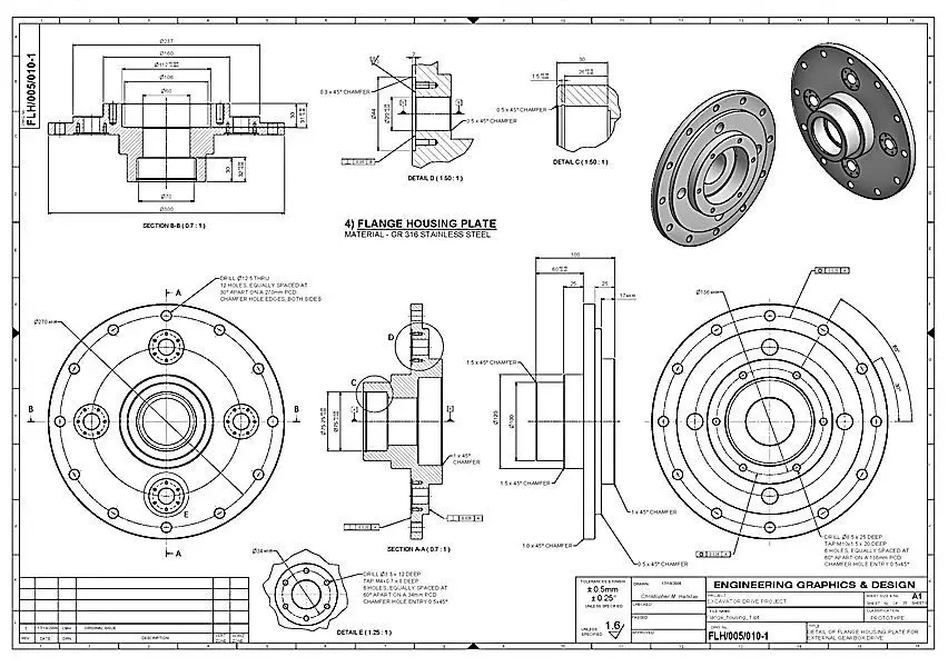
General tolerances fill the gaps left by individually dimensioned limits, but they are not a substitute for functional engineering. A clear drawing identifies the governing standard and edition, defines where it applies, and highlights features that need explicit limits or geometric control. This article explains how to make those choices and carry them through quotation and inspection.
On this page
What General Tolerances Actually Do
General tolerances establish default permissible variation for dimensions that do not carry an individual tolerance. They make a drawing usable without placing a separate limit beside every noncritical size. Their role is administrative and technical: they communicate the expected manufacturing and inspection framework for unspecified dimensions, while allowing the designer to reserve detailed controls for features that affect function.
The note must be read as part of the complete drawing. Its meaning depends on the cited standard, its edition, the selected tolerance class, dimension ranges, feature type, and any stated exclusions. A general tolerance does not automatically settle questions about datum selection, fit intent, surface condition, edge treatment, or measurement method. Those matters require explicit information when they influence acceptance.
Identify the Governing Note
Start at the title block and general notes. Look for the standard designation, edition, class, and any language that limits application to particular dimensions or drawing views. A designation without an edition can leave room for interpretation if the organization uses multiple releases or customer-specific conventions. The released drawing revision and its referenced documents should identify the governing requirement.
Then separate three categories: dimensions with explicit bilateral, unilateral, limit, or fit tolerances; dimensions governed by the general note; and dimensions that are reference-only or otherwise non-inspection dimensions. This classification prevents a common mistake: applying a default tolerance to a feature that already has a more specific requirement. When requirements conflict, the drawing’s stated order of precedence or engineering agreement should control.
- Record the drawing number, revision, and issue status.
- Confirm the standard, edition, class, and scope of the note.
- Flag every feature with a specific tolerance, fit, or geometric control.
- Ask for clarification when a note and a dimension appear inconsistent.
Choose Explicit Exceptions by Function
A default tolerance is appropriate when variation in a size or location does not materially change the part’s intended use. An explicit tolerance is justified when a feature establishes a fit, seals, locates another component, controls wall thickness, supports a bearing surface, or determines a visible alignment. The question is not whether a tighter number looks more precise; it is whether the allowed variation protects a defined functional condition.
Use the control that matches the design need. A size tolerance controls feature size, while a geometric tolerance can control location, orientation, form, or relationship to datums. For example, a hole may meet its size limits yet be misplaced relative to a mating pattern. If assembly depends on that relationship, position and datum references may express the requirement more directly than tightening diameter alone. The drawing, applicable standard, and engineering agreement should determine the final scheme.
| Drawing situation | More suitable definition | Why it helps |
|---|---|---|
| Noncritical overall length | General tolerance note | Avoids unnecessary individual callouts while retaining a stated default. |
| Mating hole pattern | Explicit position control with datums | Addresses location relative to the assembly references. |
| Shaft or bore fit | Explicit limits or fit designation | Communicates the functional size relationship directly. |
| Cosmetic outer contour | Profile or clearly defined dimensional controls when needed | Connects acceptance to the intended envelope rather than isolated dimensions. |
Build Datums Before Geometric Controls
Geometric tolerancing becomes reliable only when the datum scheme reflects how the part is located in manufacture, assembly, or inspection. Choose primary, secondary, and tertiary references that constrain the intended degrees of freedom without forcing an artificial setup. A stable mounting face, locating bore, or functional edge may be suitable, but the choice should be based on the product interface rather than convenience alone.
Avoid assigning datums merely because they are easy to dimension from in a model. A datum feature must be accessible and understandable to the people who will produce and inspect the part. If a functional reference is interrupted, flexible, thin, or difficult to contact repeatably, the inspection approach may need further definition. Communicate any fixture assumptions, datum targets, or functional gaging needs before release when they affect conformance.
Account for Material and Process Effects
Tolerance decisions should consider the material grade, feature geometry, part rigidity, stock condition, finishing sequence, and planned manufacturing route. Thin walls, deep internal features, long unsupported sections, and asymmetric material removal can make a nominal shape more sensitive to clamping and residual stress. A drawing need not prescribe a process unless necessary, but it should not assume that all geometry behaves alike.
Surface treatment and secondary operations also matter. Coatings, blasting, polishing, heat treatment, and deburring can alter dimension, edge condition, surface texture, or measurement access. If a dimension applies before or after a specified operation, say so. Likewise, identify the required material grade and any governing material or process standard. The process plan and engineering agreement should resolve questions about sequencing and inspection condition.
- Specify whether critical dimensions apply before or after a secondary operation.
- Define surface finish only where it supports function, sealing, friction, appearance, or another stated need.
- Avoid using a finish requirement as a substitute for geometric control.
- Discuss fragile or distortion-sensitive geometry early in the quotation review.
Make Inspection Intent Transferable
A toleranced drawing is also an inspection instruction. Inspectors need a clear nominal, permissible variation, datum reference frame where applicable, and a practical way to access the feature. Dimensions that are difficult to probe, hidden after assembly, or affected by free-state condition deserve an agreed measurement approach. Without it, two reasonable setups can yield different results while each follows the drawing differently.
For critical characteristics, define the reporting expectation rather than assuming that all dimensions receive identical scrutiny. A first-article report, sample plan, measurement record, functional gauge result, or certificate requirement should be stated when required by the purchase documents or engineering agreement. The appropriate method depends on the feature and standard; a general tolerance note alone does not prescribe an inspection technology, sampling method, or acceptance record.
Review Before Requesting a Quote
Before requesting a quotation, conduct a short cross-functional review of the released file set. Confirm that the model and drawing agree, all critical interfaces have explicit controls, and general tolerances have a visible scope. Check that units, decimal conventions, revision identifiers, material grade, finishes, thread designations, and purchased-item interfaces are complete. A precise request reduces avoidable interpretation cycles without turning every dimension into a special requirement.
SUUXIANG can use a well-prepared technical package as the basis for a manufacturing discussion. Where the drawing leaves a functional condition uncertain, resolve it through the responsible design authority rather than relying on an assumed shop convention. Record approved clarifications in the controlled drawing, specification, or engineering agreement so that quotation, production, and inspection are working from the same requirement.
- Provide the released drawing and the corresponding model, identifying which document governs if they differ.
- List critical-to-function features and their intended mating conditions.
- Include applicable standards, revision-controlled specifications, and finish sequence requirements.
- Request written resolution of ambiguous tolerances before purchase release.
Questions engineers ask
Does a general tolerance apply to every dimension on the drawing?
No. It normally applies only within the scope stated by the governing note and only where a more specific tolerance, fit, geometric control, reference designation, or other instruction does not override it. Read the title block, notes, and drawing-specific exceptions together.
When should a designer replace a general tolerance with a specific one?
Use a specific requirement when variation affects fit, assembly, sealing, motion, appearance, safety, or a defined interface. Select size limits, a fit designation, or an appropriate geometric control according to the functional need and the governing drawing standard.
Can inspection infer a datum scheme from ordinary dimensions?
It should not need to for a feature that requires geometric verification. If location or orientation is functionally important, define datum features and the relevant geometric control on the drawing. Where the setup or measurement condition remains unusual, document it in the inspection requirement or engineering agreement.
References and further reading
These resources explain related design and manufacturing principles. Project limits, acceptance criteria and process choices must be agreed against the current drawing.
Publication note: this article is general design guidance, not a material specification, a certified inspection report or a guarantee of process capability.
Turn the drawing into a clear manufacturing brief.
Share the current drawing, material, finish and inspection requirements for a project-specific discussion.