
Engineering resource
Annotated CNC Drawing Example Pack
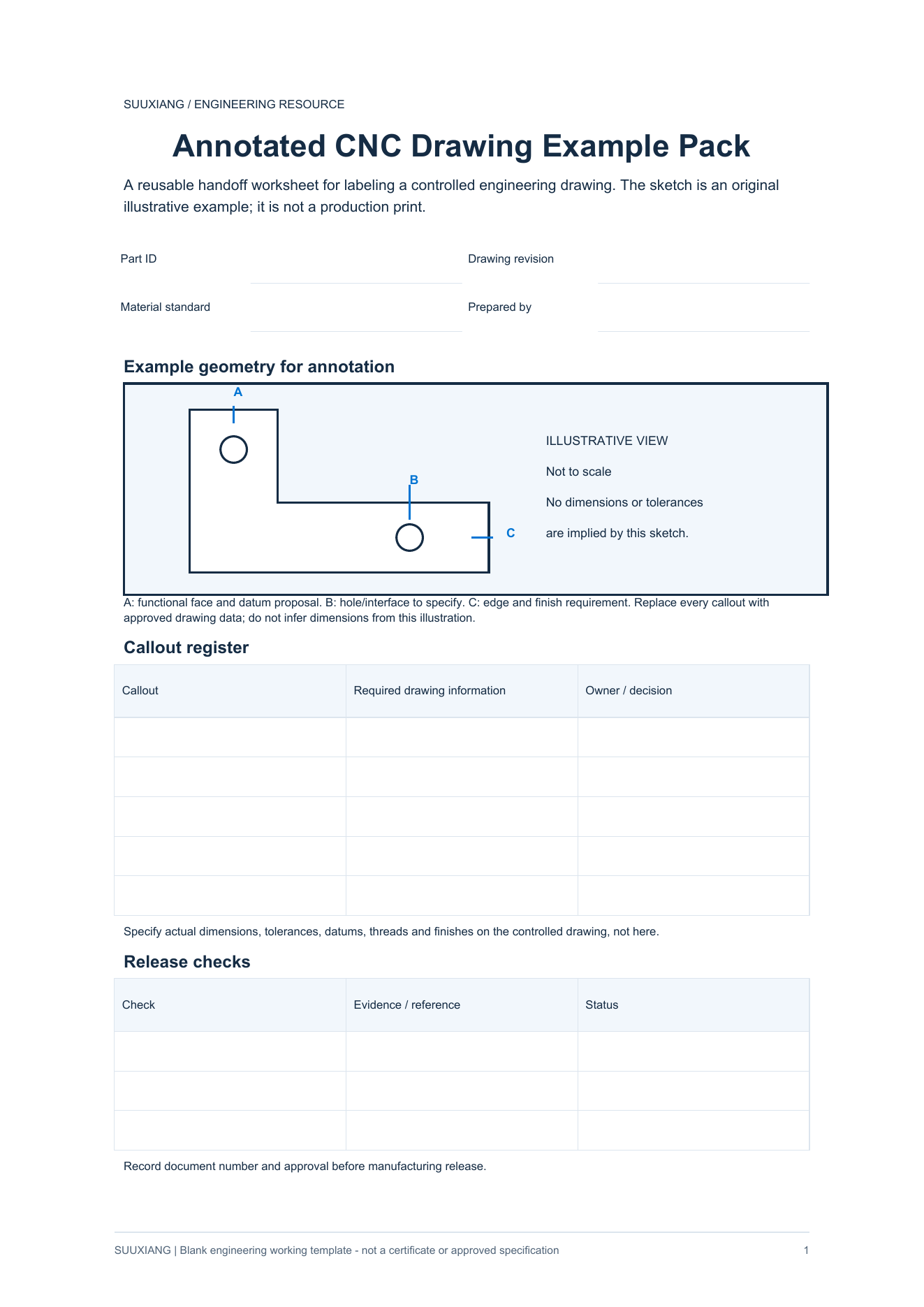
This resource explains how to turn the supplied blank PDF into an illustrative CNC drawing example pack. It shows how to label geometry, dimensions, holes, threads, datums, notes, and revision status without treating the sheet as a production release. Attach the controlled records that define requirements, then route the completed pack to the people authorized to approve it.
Download the blank working template
This editable-by-hand PDF is a blank engineering worksheet, not a completed inspection report, certificate, customer record or approved specification.
Download PDF template →On this page
What the blank PDF captures
The blank PDF is a working layout for an annotated CNC drawing example pack. It can capture a part identifier, drawing revision, projection views, dimensions, feature callouts, general notes, datum references, and a review block. Its purpose is to make the intended communication visible and easy to discuss before someone relies on the information for manufacturing or verification.
Use an illustrative component rather than a customer-controlled production part. Give the example a neutral identifier, such as Example Bracket A, and clearly mark it as illustrative. The sheet should distinguish shown dimensions from reference information, identify the governing units, and leave room for assumptions that require confirmation in the released drawing or engineering agreement.
- Record the drawing number or internal reference and revision.
- Identify units, projection convention, and sheet status.
- Reserve fields for material, finish, and critical notes when applicable.
Build the illustrative callouts
Create front, top, and side views that reveal the features a machinist or reviewer needs to interpret. Add an isometric view only when it improves orientation; it should not replace dimensioned orthographic views. Establish datums from functional surfaces where the design intent supports them, then locate features from those datums rather than accumulating dimension chains.
For example, label a mounting face as datum A, a perpendicular locating edge as datum B, and a secondary edge as datum C. Callout 1 may identify an overall profile dimension. Callout 2 may locate a hole pattern from A, B, and C. Callout 3 may define a threaded hole with its thread designation and depth where required. Callout 4 may point to a corner treatment or surface requirement. The released drawing, applicable standard, and approved process plan control the actual requirements.
- Use leaders that terminate on the intended feature.
- Avoid duplicate dimensions or competing locations.
- Mark reference dimensions clearly when they are informational only.
- State tolerances only when the governing drawing, standard, or agreement defines them.
| Illustrative callout | What it communicates |
|---|---|
| 1: Datum feature | The surface or edge used as a measurement reference. |
| 2: Hole feature | Diameter, location basis, quantity, and any required depth. |
| 3: Thread feature | Thread designation and engagement or depth requirement when specified. |
| 4: Edge or finish note | A localized requirement linked to the applicable drawing note. |
Attach controlled supporting evidence
The annotated sheet is only one part of the record. Attach or reference the controlled design drawing, revision history, approved material specification, relevant standards, and any customer or engineering agreement that changes default interpretation. If dimensional verification is planned, include the approved inspection approach or inspection record separately, with the instruments, sampling basis, acceptance criteria, and results required by the governing quality system.
Where a feature depends on machining sequence, fixturing, deburring, heat treatment, coating, or another downstream operation, link the pack to the applicable process plan or traveler. Do not infer a material grade, finish, tolerance, or verification method from a visual example. Those decisions belong to the controlled technical definition.
- Attach the released drawing or an unambiguous controlled reference.
- Reference applicable material and finish specifications.
- Link process and inspection records when those records are required.
- Record deviations only through the authorized change or concession process.
Review, approve, and retain
Before circulation, check that callouts match the intended views, notes do not conflict, and the revision identifier is complete. The design authority should approve the interpretation of functional requirements. The responsible manufacturing reviewer should confirm that the drawing communicates the intended features for planning. A quality reviewer should approve the inspection interpretation when the organization’s procedures require it. Approval roles and signatures are controlled by the organization’s document system or engineering agreement.
Retain the completed example pack with its referenced evidence and approval record so later readers can determine which revision was reviewed. If the part definition changes, revise the example pack or mark it superseded. A drawing example is useful for communication, but it must not become an uncontrolled substitute for the current released technical data.
- Confirm the current revision before review.
- Assign approvers according to the documented responsibility matrix.
- Preserve links to the controlled evidence used during approval.
Know the pack’s limits
A blank template is not a certificate, a completed inspection, a manufacturing instruction, or proof that any part conforms. Completing an illustrative pack does not establish capability, validate a process, authorize production, or replace a released drawing. It also cannot settle conflicts among specifications; the governing contract documents, drawing, standards, and approved engineering decisions determine the answer.
Use the pack to expose unclear callouts early. When a requirement cannot be stated without interpretation, flag it for the design authority instead of inventing a universal rule. Particular geometry, material behavior, tolerancing practice, and inspection method may require specialist review and an agreed technical definition.
- Do not use the blank PDF as evidence of inspection.
- Do not release it as a stand-alone production document.
- Escalate ambiguous requirements to the authorized engineering owner.
Questions engineers ask
Is this blank PDF a certificate or completed inspection record?
No. It is a layout for an illustrative annotated drawing example. A certificate, inspection record, or conformance statement requires the controlled evidence, approvals, and results required by the applicable quality system and agreement.
Who approves the completed drawing example pack?
The design authority approves design interpretation. Manufacturing and quality reviewers participate where their documented responsibilities require it. The exact approval path, authority, and retention method are set by the organization’s controlled document process or engineering agreement.
References and further reading
These resources explain related design and manufacturing principles. Project limits, acceptance criteria and process choices must be agreed against the current drawing.
Publication note: this article is general design guidance, not a material specification, a certified inspection report or a guarantee of process capability.
Turn the drawing into a clear manufacturing brief.
Share the current drawing, material, finish and inspection requirements for a project-specific discussion.