
Engineering article
Designing Dovetail Features for CNC Machining
Dovetail features create compact, self-locating mechanical interfaces, but their performance depends on more than the included angle. Designers must define the functional flanks, clearance strategy, assembly path, datum scheme, and inspection method together. A clear drawing and process-aware handoff help turn an attractive cross-section into a measurable, manufacturable interface.
On this page
Start With the Interface Function
A dovetail is often selected because its angled flanks resist separation in one direction while guiding a component along an assembly axis. That apparent simplicity can hide several different functions: sliding adjustment, removable retention, fixed location after clamping, load transfer, or wear-managed replacement. The intended function should govern the geometry rather than a preferred angle carried over from an unrelated design.
First identify the direction of insertion, the directions of working load, and the surfaces intended to establish location. A dovetail may be expected to carry a lateral load through both flanks, locate on one flank while the opposite flank clears, or rely on a separate screw or clamp to generate contact. These conditions produce different dimensional and surface requirements, even when the profile looks similar.
Choose Geometry as a System
The included angle, throat width, root width, depth, flank length, and transition radii interact. Changing one dimension can alter cutter access, local stiffness, available engagement, and the ability to inspect the finished surfaces. A deeper form may increase contact area, yet it can also create a narrow internal region that is harder to machine and clean. The drawing should make the governing profile unambiguous in a section view.
Internal corners deserve early attention. CNC cutting tools produce radii where a theoretical sharp internal corner would appear, and those radii affect whether the mating part can fully seat. Relief features can create clearance, but they should be intentional and located away from functional bearing surfaces. The allowable relief shape, material grade, and process plan should be agreed when they influence strength, wear, or fit.
Separate Location From Clearance
A reliable mating concept states where contact is required and where space is required. For a sliding dovetail, uncontrolled contact on every surface can create binding when form variation, burrs, coating buildup, debris, or thermal conditions are present. Designers commonly assign primary location to selected flanks and provide deliberate clearance at non-locating faces, but the appropriate arrangement depends on the assembly and load case.
Do not define fit only with a nominal profile. State the functional relationship between the male and female components, including whether motion must be smooth, whether adjustment is allowed, and whether a preload device changes the final contact condition. Where a fit class or tolerance scheme is important, the governing standard, engineering agreement, or mating drawing should control the requirement. A sectioned assembly view often exposes conflicts that isolated part drawings conceal.
| Design intent | Geometry emphasis | Inspection focus |
|---|---|---|
| Sliding adjustment | Controlled flank relationship with purposeful clearance | Profile, flank position, travel smoothness |
| Fixed location with clamp | Repeatable locating faces and clamping clearance | Datum-related flank geometry, seating surfaces |
| Replaceable captured member | Insertion path, retention faces, wear allowances | Throat access, engagement, replaceable-part compatibility |
Plan Tool Access Before Detailing
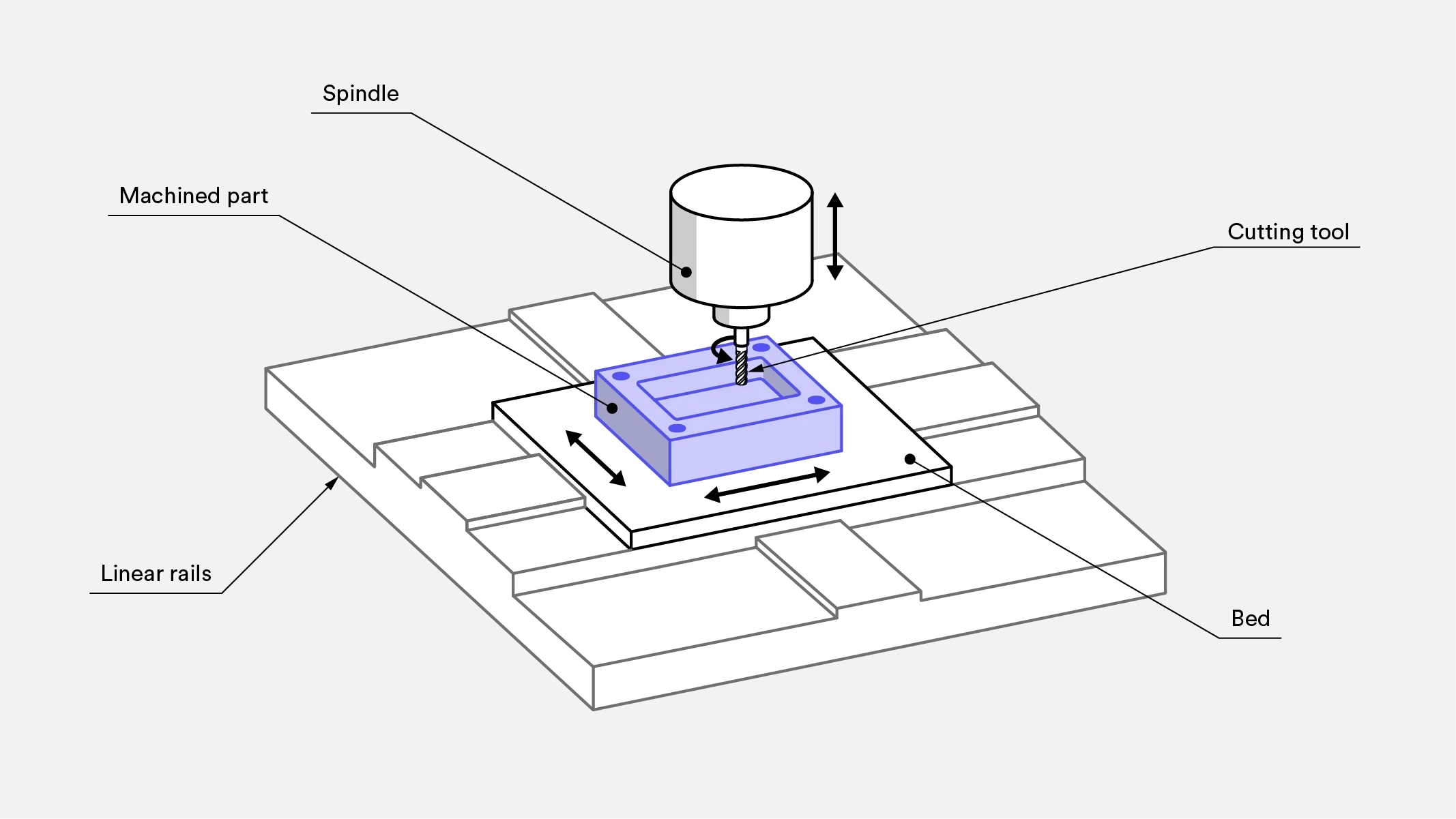
Dovetail cutters require an approach path and enough room for the cutter body, shank, and adjacent machining operations. Nearby walls, shoulders, fillets, fastener heads, and deep pockets can block access even when the cutting diameter fits the final profile. The machining orientation matters as well: a feature that is accessible in one setup may require repositioning when its reference faces are on another side of the part.
Consider the sequence, not merely the finished shape. A machinist may establish broad datum faces first, rough the surrounding pocket, finish the dovetail flanks, and then machine associated holes or reliefs. Later operations can introduce burrs or compromise a delicate edge. If an edge-break requirement, surface condition, or protected contact zone matters, place it explicitly on the drawing and discuss how it aligns with the proposed process plan.
Dimension the Functional Profile
A dovetail drawing should communicate the profile from datums that reflect how the part is held, located, and measured. Dimensioning to a nonfunctional exterior edge may be convenient on screen but can create a chain of uncertainty between the measured value and the actual mating condition. Datum surfaces should be stable, accessible, and meaningful to the assembly.
Use a profile control or other suitable geometric control when the complete form and its relationship to datums matter more than a collection of separate angle and width limits. Conversely, individual dimensions can be appropriate when each has a distinct functional purpose. The selected method should identify the controlled surfaces clearly, avoid contradictory limits, and leave no doubt about whether the root, flanks, throat, or relief is functional. A two-dimensional drawing remains valuable when it captures requirements that a solid model alone does not express.
Make Inspection Physically Possible
Inspection access is a design constraint. The narrowest portion of a female dovetail can be difficult to reach with conventional contact tools, while angled flanks may be awkward to probe without suitable fixturing. A tolerance is only useful when the team can establish the datums and verify the controlled condition with an agreed method. Inspection planning should begin while geometry can still be changed easily.
Define whether acceptance depends on direct dimensional measurement, profile evaluation, functional gauging, or assembly verification. Functional gauging can be especially useful when the interface matters more than a single isolated dimension, provided the gauge condition is documented. If a coordinate measuring method, special fixture, test assembly, or measurement report is required, include that expectation with the quotation package. The drawing and engineering agreement control the acceptance method where necessary.
Prepare a Complete Quote Package
A strong pre-quote package reduces interpretation cycles. Supply the current model and drawing, a clear section through each dovetail, the mating component or an interface-control sketch, material grade, required finish condition, quantity, and revision status. Explain whether the feature is cosmetic, clearance-only, load-bearing, sliding, or a primary locator. That context helps reviewers focus questions on the characteristics that actually affect the part’s use.
Also identify controlled surfaces, datum references, deburring restrictions, protective masking needs, and any required documentation. If the feature will be coated, heat treated, or finished after machining, clarify whether the mating dimensions apply before or after that operation. Request feedback on cutter access, likely setup strategy, and inspection practicality. The result is not a predetermined manufacturing answer; it is a better basis for aligning the drawing, material, process plan, and acceptance criteria.
- Provide a sectioned assembly view that shows the intended insertion direction.
- Mark locating flanks, clearance faces, and surfaces that must remain free of burrs.
- State whether post-machining finishing changes the functional dimensions.
- Include the revision-controlled drawing whenever the model lacks complete tolerance information.
Questions engineers ask
What is the most important dimension on a dovetail feature?
There is no universal single dimension. The critical characteristic is the one that governs the intended mating function, often the relationship of the locating flanks to assembly datums. The drawing should identify that relationship and its acceptance method.
Should every dovetail surface be tightly controlled?
No. Tight controls should be reserved for surfaces that affect location, retention, load transfer, or motion. Intentional clearance on nonfunctional faces can improve assembly robustness and simplify manufacturing, subject to the design requirements.
How should a dovetail be inspected?
Use a method that can reach the feature and reproduce the drawing datums. Depending on the geometry and requirement, this may involve dimensional checks, profile measurement, a documented functional gauge, or controlled assembly verification.
References and further reading
These resources explain related design and manufacturing principles. Project limits, acceptance criteria and process choices must be agreed against the current drawing.
Publication note: this article is general design guidance, not a material specification, a certified inspection report or a guarantee of process capability.
Turn the drawing into a clear manufacturing brief.
Share the current drawing, material, finish and inspection requirements for a project-specific discussion.