
Engineering article
Designing Undercuts for CNC Machining
Designing undercuts for CNC machining starts with a tool-access question, not a shape preference. This article explains how cutter form, approach direction, clearance, surface requirements, and inspection affect feasible geometry. It also compares alternatives when a feature cannot be reached economically and provides a drawing-handoff checklist before quotation.
On this page
- Begin With the Functional Requirement
- Map Tool Access Before Dimensioning
- Choose Geometry That Fits Available Cutters
- Balance Feature Complexity Against Alternatives
- Control Tolerances Where They Matter
- Prepare the Drawing and Inspection Handoff
- Use a Pre-Quote Undercut Checklist
- References and further reading
Begin With the Functional Requirement
An undercut is a recessed feature whose geometry cannot be produced by a conventional end mill approaching along the main machining direction. It may retain a mating component, provide thread or seal clearance, create a relief at a shoulder, or separate surfaces that must not contact. For CNC machining, the important question is not simply whether the feature is called an undercut. The key question is which cutting tool can reach the required surfaces without the holder, shank, adjacent wall, or part itself colliding.
Start by identifying what the feature must accomplish. A groove used solely to prevent a sharp internal corner from interfering with an assembled shaft can often accept a simple relief. A feature that captures a seal, spring, or retaining element may need a controlled profile and surface. A concealed decorative recess may allow a different process direction or a revised part split. Distinguishing these cases prevents a cosmetic geometry choice from becoming an unnecessary machining constraint.
- State whether the undercut provides clearance, retention, sealing, assembly relief, or another specific function.
- Identify the surfaces that contact another component and the surfaces that only need to clear it.
- Separate controlled functional geometry from nonfunctional material removal in the model and drawing.
Map Tool Access Before Dimensioning
Tool access is governed by the cutter’s cutting edge, neck, shank, holder, and usable reach. A narrow groove may admit the cutting edge but still block the larger tool body before the required depth is reached. An internal shoulder can create the same issue even when the opening appears generous in a front view. Evaluate the complete approach path in section, including the entry opening, the feature depth, nearby radii, and the space needed to move the cutter into and out of the cut.
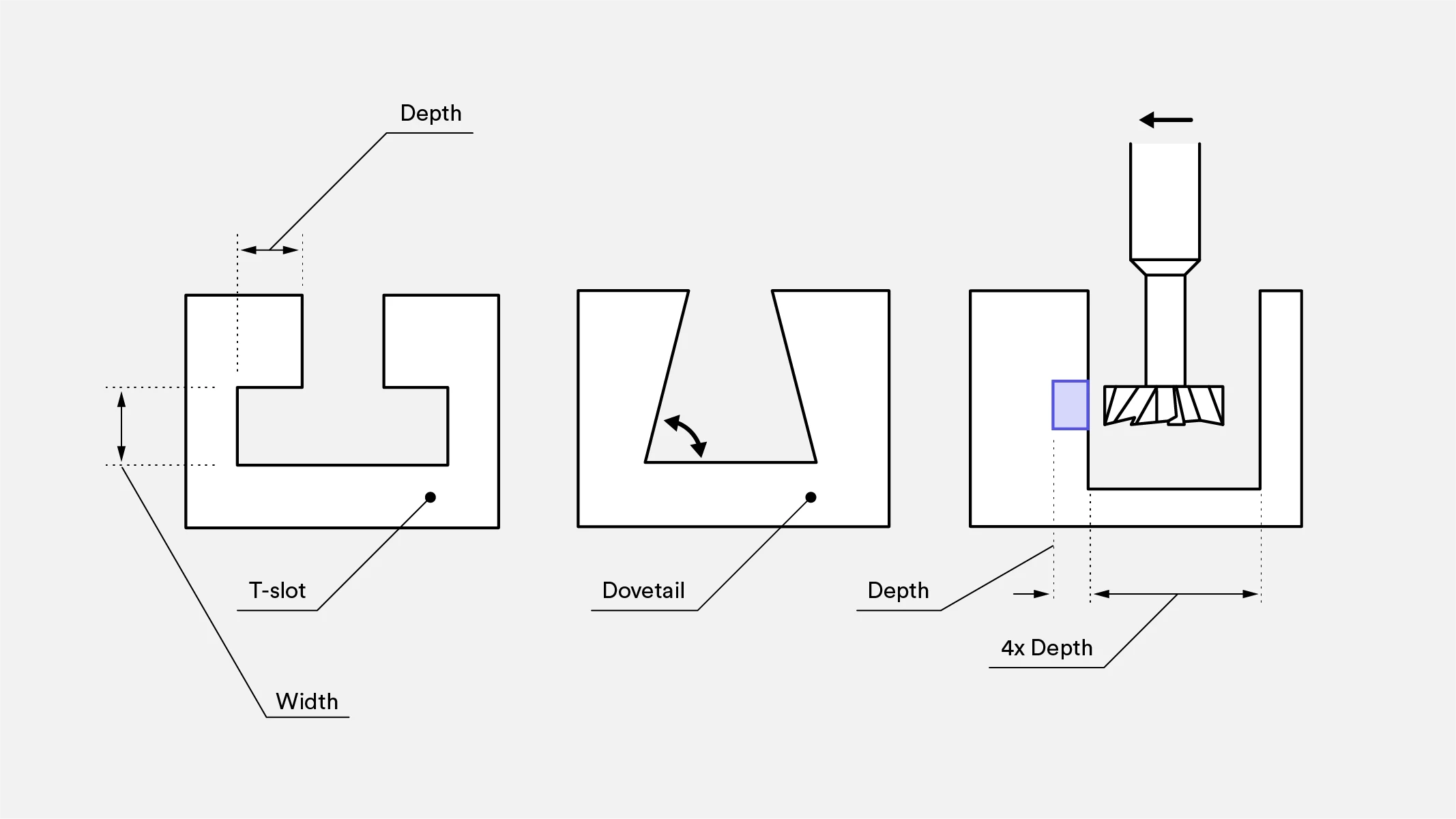
Access direction matters as much as feature size. A turning operation can reach many rotational undercuts efficiently when the part geometry and setup support it. Milling may address side-access grooves, T-slot-like forms, and localized recesses with specialized cutters. Multi-axis positioning can change approach direction, but it does not eliminate clearance limits. The selected manufacturing route should follow the actual datum scheme, material grade, geometry, production context, and process plan rather than an assumed machine capability.
- Check access in a section normal to the intended cutter path.
- Account for holder and shank clearance, not only the cutting diameter.
- Mark features that require machining from a side, back face, bore, or secondary setup.
Choose Geometry That Fits Available Cutters
A standard-compatible relief is generally easier to communicate and evaluate than an arbitrary narrow profile. The cutter must have sufficient width or radius to create the specified floor and sidewalls, while leaving clearance at the root of adjacent faces. Very sharp internal transitions, deep slender grooves, and profiles that combine small radii with restricted access can demand specialized tooling or multiple passes. That may be appropriate when the interface requires it, but the drawing should make the requirement deliberate rather than accidental.
Avoid treating a nominal CAD edge as proof that a sharp internal corner is required. Cutting tools leave a radius or relief shape, and the permitted condition should be shown explicitly. If a mating part needs clearance, define the mating envelope or minimum relief needed. If an exact profile is necessary, define it with dimensions, radii, datums, and an appropriate profile control where applicable. The governing drawing, applicable standard, and engineering agreement should determine the final definition.
- Prefer a stated root radius or relief form over an implied perfectly sharp internal corner.
- Keep groove walls and adjacent faces sufficiently clear for the chosen cutting path.
- Specify custom form geometry only where the assembly or performance requirement depends on it.
Balance Feature Complexity Against Alternatives
When access is marginal, redesign may be more valuable than forcing a difficult machining sequence. A feature can sometimes move to an exposed edge, become a through-relief, be divided across two mating components, or be created before a later assembly step. In other cases, a separate retainer, spacer, threaded connection, or change in mating geometry can provide the same function. These are engineering choices, so the assembly load path, service environment, material behavior, and applicable requirements need review before replacing an undercut.
The best alternative depends on what the undercut does, not on a universal cost rule. A groove that establishes seal placement should be assessed around the specified seal design and surface requirement. A clearance feature may tolerate a broader relief. A captive feature may need a retained component or assembly change. Discussing alternatives early lets the part geometry, inspection method, and manufacturing plan develop together instead of making the machinist infer a design change from an inaccessible detail.
| Design response | When it can help | Engineering question to resolve |
|---|---|---|
| Tool-accessible relief | A hidden corner needs noncontact clearance | What minimum clearance envelope is actually required? |
| Feature moved to an open edge | The function does not depend on being enclosed | Will assembly, strength, or appearance change? |
| Secondary component or retainer | Retention can be separated from the base part | How will load, service, and assembly be controlled? |
| Reoriented or multi-setup machining | The geometry is functionally fixed but has another reachable direction | Which datums and surfaces must remain consistent across setups? |
| Custom cutter profile | The required form cannot be simplified | What profile, surface, tolerance, and inspection evidence are necessary? |
Control Tolerances Where They Matter
An undercut can involve several independent controls: its location from a datum, width, depth, root radius, sidewall orientation, surface condition, and relationship to a bore or shoulder. Applying a tight general tolerance to every element can obscure the actual functional need and make inspection unclear. Instead, identify which dimension establishes assembly clearance or retention, then relate it to the datum surfaces used by the mating condition. Dimensions without a functional role can often remain less restrictive if the drawing permits.
Tolerance selection must reflect the material grade, feature accessibility, cutting method, part rigidity, and process plan. A deep internal groove may be measured differently from an exposed shoulder groove. If a profile or position requirement governs the result better than separate coordinate dimensions, use the control appropriate to the drawing standard. Where measurement access is limited, agree on the inspection approach before release. A requirement is only useful when the defined part condition and verification method can be understood consistently.
- Dimension groove location from the same functional datum structure used by the mating interface.
- Call out width, depth, radius, and surface requirements only when each affects function.
- Clarify whether a limit, profile, position, runout, or other standard-based control governs the critical relationship.
Prepare the Drawing and Inspection Handoff
A model can conceal the details that determine whether an undercut is reachable and measurable. Provide a local section view through the feature, especially for internal grooves, reverse-side forms, and compound transitions. Show the approach-facing opening and any nearby geometry that restricts travel. Use detail views when the feature is small relative to the part. If a modeled radius or relief is informational rather than controlled, make that status clear under the drawing convention in use.
Inspection planning should follow the characteristic being controlled. An exposed groove may be accessible with direct dimensional measurement, while an internal or obstructed feature may require a suitable bore-measurement method, replica approach, fixture, optical technique, or other agreed method. Do not assume that a nominal CAD measurement is sufficient evidence of a finished feature. Define acceptance around the drawing and agreed quality plan, including any sampling, reporting, or first-part documentation requirements that apply to the project.
- Include a section or detail view that exposes the complete undercut profile.
- Identify datum surfaces and critical feature relationships in the drawing.
- Discuss measurement access for concealed or restricted features during quotation review.
Use a Pre-Quote Undercut Checklist
Before requesting a quotation, review the part from the perspective of a cutter traveling toward the feature. Confirm whether the model contains unintentionally sharp corners, duplicate dimensions, ambiguous depth references, or inaccessible inspection points. Then provide the information needed to judge feasible tool access without guessing at product function. Early clarification is particularly useful when an undercut is inside a bore, below an overhang, close to a finished cosmetic face, or located on a thin section that could respond differently during machining.
For SUUXIANG project discussions, a concise package can focus attention on the questions that change the manufacturing route: the released drawing revision, 3D model, material grade, required standard, relevant assembly interface, critical characteristics, and requested documentation. If the feature has an established mating part, a controlled interface model or dimensional envelope can be more useful than a broad statement that clearance is needed. This helps align technical review with the design intent without assuming a particular method or outcome.
- Provide the released drawing, model, material grade, revision level, and applicable standards.
- Flag every undercut that is critical to assembly, sealing, retention, or appearance.
- Provide mating-envelope information where clearance is the real requirement.
- Ask whether the proposed geometry has a clear machining and inspection path before design release.
Questions engineers ask
Can any undercut be machined with a small enough cutter?
No. A smaller cutting edge does not solve shank, holder, entry, reach, rigidity, or inspection restrictions. The full tool path and surrounding geometry must be evaluated against the drawing, material, and process plan.
Should an internal undercut have a sharp corner?
Only if the functional requirement truly calls for a defined sharp condition and the drawing establishes how it is controlled. In many designs, a stated radius or relief gives the mating part the needed clearance and better represents a machinable result.
What information should accompany an undercut request for quotation?
Provide the model and released drawing, material grade, quantity context if relevant, applicable standards, critical dimensions and datums, surface requirements, mating-interface information, and any required inspection documentation. A section view of concealed geometry is especially useful.
References and further reading
These resources explain related design and manufacturing principles. Project limits, acceptance criteria and process choices must be agreed against the current drawing.
Publication note: this article is general design guidance, not a material specification, a certified inspection report or a guarantee of process capability.
Turn the drawing into a clear manufacturing brief.
Share the current drawing, material, finish and inspection requirements for a project-specific discussion.