
Engineering article
Free-State vs Restrained Inspection of Thin Parts
Thin parts can appear nonconforming when an inspection fixture changes their natural shape. The key decision is not simply how to measure, but which functional condition the drawing intends to control. This article explains how to define free-state and restrained inspection, connect them to datum strategy, and prepare a clear inspection handoff before quotation.
On this page
- Why Thin Parts Need a Condition
- Free-State Inspection Defines Natural Shape
- Restrained Inspection Represents Functional Assembly
- Choose Based on Function, Not Convenience
- Build Datum Logic Before Fixture Design
- Account for Manufacturing History
- Write an Unambiguous Inspection Handoff
- References and further reading
Why Thin Parts Need a Condition
A thin part is not necessarily unstable; it may simply be compliant enough that gravity, probing force, support spacing, or clamp load changes the observed geometry. A panel, cover, ring, webbed housing, or thin-wall machined feature can therefore produce different measurements while remaining the same physical part. The inspection condition must identify which of those shapes matters to the product function.
For SUUXIANG project discussions, the useful opening question is: should the part be evaluated as it naturally rests, or as it sits in its intended assembly interface? That decision frames the datum scheme, fixture concept, measurement program, and disposition of borderline results. Without it, a numerical report can look precise while answering the wrong acceptance question.
Free-State Inspection Defines Natural Shape
Free-state inspection evaluates the part with only the support needed to prevent accidental movement or unsafe handling. The support strategy should avoid forcing the component into a nominal shape. This condition is often relevant where the delivered part must retain a controlled unassembled form, where cosmetic appearance is judged before installation, or where a drawing explicitly defines an unconstrained profile, flatness, or contour requirement.
Free-state does not mean careless placement. The inspection plan still needs stable datum contact, repeatable orientation, suitable support points, and a documented method for handling flexible features. An unrestricted probe path can itself deflect a thin wall, so noncontact scanning, reduced-force probing, or an agreed sampling approach may be appropriate when the engineering requirement permits it.
Restrained Inspection Represents Functional Assembly
Restrained inspection measures a part after controlled contact with a fixture that represents relevant mating surfaces or assembly constraints. It is appropriate when fasteners, seals, perimeter supports, locating pins, or mating geometry establish the functional shape. The fixture is not merely a convenience for the inspector; it becomes part of the acceptance definition and should reflect the engineering intent rather than an arbitrary attempt to remove distortion.
A restrained condition needs more detail than a note saying to clamp the part. The drawing or inspection specification should identify primary, secondary, and tertiary locating features, contact regions, restraint directions, sequence of engagement, and any allowed gaps. It should also clarify whether clamps represent assembly loads, provide only retention, or are prohibited from influencing the feature under evaluation. The applicable engineering agreement controls these choices.
Choose Based on Function, Not Convenience
The correct condition follows the failure mode that the requirement is meant to prevent. If an exposed cover must look smooth before installation, free-state form may be central. If a thin sealing flange functions only after it is located against a mating face, restrained profile or gap may better reflect the real risk. Some components require both conditions because shipping appearance and assembled performance are separate concerns.
A hybrid specification can be useful, but only if each result has a clear purpose. For example, a free-state limit may protect handling or appearance, while restrained measurements verify fit at selected interfaces. Treating a restrained result as proof of free-state shape, or vice versa, obscures the tradeoff. Each reported result should name its condition, fixture revision, datum alignment, and evaluated feature set.
| Inspection condition | Best suited to | Primary risk if unspecified |
|---|---|---|
| Free-state | Natural form, unassembled appearance, unconstrained interfaces | Support or probe contact changes the reported shape |
| Restrained | Assembly-dependent fit, sealing, attachment, located interfaces | Fixture clamping masks a requirement that should remain free |
| Both conditions | Separate delivery and installed functions | One result is incorrectly used to accept every requirement |
Build Datum Logic Before Fixture Design
A fixture should follow the datum framework, not replace it. Start with the surfaces, features, or axes that establish how the part interfaces with the next assembly. Then identify which contacts locate degrees of freedom and which contacts only stabilize the component. For flexible parts, excessive contact points can create a deceptively favorable result, while too few can make the orientation inconsistent. The functional drawing definition governs the intended balance.
The inspection handoff benefits from a simple restraint map. It can show datum contacts, temporary supports, clamp directions, measurement zones, and areas excluded from direct contact. It should also distinguish functional locators from inspection-only aids. When a feature must be measured after restraint, the map should state whether that restraint remains active during the scan or probing sequence.
- Identify the interface features that establish the assembly position.
- Separate locating contacts from supports and from clamps.
- State fixture contact material or protection where finish sensitivity matters.
- Control the fixture revision alongside the measurement program.
Account for Manufacturing History
Observed shape can reflect residual stress, material removal sequence, thermal history, wall transitions, or local feature density. Thin-wall machining may expose stress as stock is removed, while additive parts can be sensitive to orientation, supports, and post-processing history. These factors are reasons to plan the requirement carefully; they are not grounds to assume a specific outcome from every part or process.
Design choices can reduce uncertainty before inspection begins. Gradual transitions, thoughtful placement of slots and holes, and functional rib or return geometry may improve stiffness where the design allows. Material grade, heat treatment condition, finishing route, and process plan can each change the practical response. A drawing, applicable standard, or agreed process plan should determine what is controlled and what evidence is required.
Write an Unambiguous Inspection Handoff
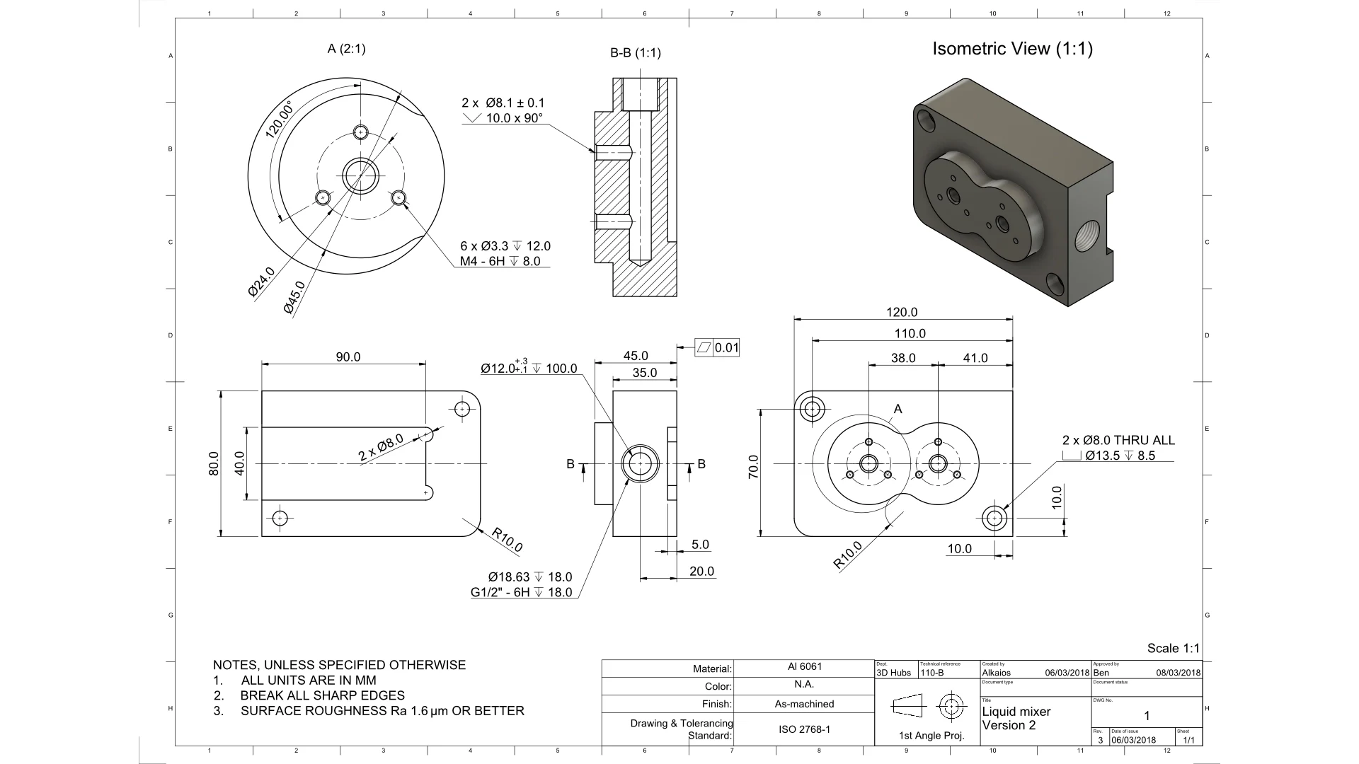
A strong handoff prevents a supplier, inspector, and design team from making different assumptions about the same thin feature. Provide the released model and drawing, identify critical functional interfaces, and state the governing condition for each controlled characteristic. If a dedicated fixture is required, include its concept or a reference to the controlled fixture drawing. Do not rely on a screenshot alone to convey datum precedence or clamp intent.
Before quotation, review whether the requested condition can be repeated at incoming inspection, during first article review, and when a discrepancy is investigated. Clarify measurement technology, reporting format, sampling basis where applicable, and the treatment of measurements near supports or clamps. If the acceptance definition remains uncertain, resolve it through engineering agreement before turning an exploratory setup into a production inspection requirement.
- Which features govern assembly, appearance, sealing, or clearance?
- Is each feature accepted free-state, restrained, or under both conditions?
- What datum contacts, supports, and restraints are permitted?
- Which drawing revision, fixture revision, and measurement report fields must be used?
Questions engineers ask
Can a restrained fixture be used for every thin part?
No. It is appropriate only when the restrained state represents the requirement being assessed. If natural shape, unassembled appearance, or an unconstrained interface matters, free-state evaluation may also be required. The drawing or engineering agreement should define the governing condition.
Does a free-state measurement require no support at all?
No. The part may need carefully selected support to establish repeatable orientation and prevent movement. The goal is to avoid meaningful deformation from support, gravity management, or measurement contact, while documenting the method well enough to repeat it.
What should be provided with a request for quotation?
Provide the released drawing and model, material grade where specified, critical features, datum scheme, inspection condition, fixture concept if applicable, and reporting expectations. Include any assembly interface information needed to interpret restrained measurements.
References and further reading
These resources explain related design and manufacturing principles. Project limits, acceptance criteria and process choices must be agreed against the current drawing.
Publication note: this article is general design guidance, not a material specification, a certified inspection report or a guarantee of process capability.
Turn the drawing into a clear manufacturing brief.
Share the current drawing, material, finish and inspection requirements for a project-specific discussion.