
Engineering article
Maximum Material Condition in Machined Part Inspection
Maximum material condition (MMC) links a feature’s size to its available geometric tolerance. It can simplify functional inspection when the drawing defines the datum scheme, feature type, and modifier intent clearly. Reliable use depends on separating feature size, geometric error, datum simulation, and any drawing-specific acceptance requirements before machining or inspection begins.
On this page
MMC Connects Size and Geometry
Maximum material condition in machined part inspection is a geometric dimensioning and tolerancing concept, not a blanket machining allowance. For an internal feature such as a hole, MMC is its smallest permitted size because that condition leaves the most material in the part. For an external feature such as a pin, MMC is its largest permitted size. The drawing establishes the applicable limits; inspection does not infer them from a nominal dimension alone.
When MMC follows a geometric tolerance in a feature control frame, the stated geometric tolerance applies when the controlled feature is at MMC. As the actual feature departs from MMC toward less material, additional geometric tolerance may become available. This size-dependent increase is commonly called bonus tolerance. It can preserve a functional assembly boundary while allowing reasonable manufacturing variation away from the limiting material condition.
Read the Feature Control Frame
Interpretation starts by reading the complete feature control frame rather than isolating the MMC modifier. Identify the controlled feature, the geometric characteristic, the tolerance value, any diameter symbol, the datum sequence, and each modifier. Position applied to a hole has a different inspection logic from straightness applied to a shaft. A modifier after a datum reference can also change how that datum is established during inspection.
The limits associated with the feature matter just as much. A hole sized 10.00 to 10.20 has an MMC size of 10.00; a positional tolerance of 0.10 at MMC can gain 0.12 when the measured hole is 10.12. That arithmetic is only valid if the drawing actually applies MMC to that tolerance and no note, standard, or engineering agreement changes the rule. Units, limit format, and governing standard must be checked before calculation.
- Verify whether the modifier follows the controlled tolerance or a datum reference; those locations serve different purposes.
- Treat a basic location dimension as theoretically exact location information, evaluated through the related geometric control.
- Escalate unclear symbols, legacy conventions, or conflicting notes to the drawing authority before acceptance.
Use Virtual Condition Carefully
MMC is often selected to protect a mating condition. For a hole controlled for position at MMC, the smallest allowable hole combined with its positional tolerance creates a functional boundary often described as virtual condition. A functional pin gauge may test that boundary in one action when the feature pattern, datum simulation, and gauge design faithfully represent the drawing. Passing such a gauge can be highly relevant to assembly, but it does not automatically prove every separately specified requirement.
Virtual condition is useful because it translates a design intent into an inspectable boundary. It is also easy to misuse. Surface condition, depth, perpendicularity, thread form, profile controls, and datum contact details may affect function but sit outside a simple fixed gauge test. Inspection planning should state exactly what the gauge represents and which characteristics require separate dimensional or coordinate measurement.
| Inspection approach | Best suited decision | Key limitation |
|---|---|---|
| Functional gauge | Whether a feature pattern clears a defined assembly boundary | Only valid when gauge and datum simulation match drawing intent |
| Coordinate measurement | Measured size, location, orientation, and calculated bonus tolerance | Requires a documented alignment and sampling strategy |
| Attribute size gauge | Whether an individual feature meets size limits | Does not establish geometric compliance by itself |
Separate Bonus from Datum Shift
Bonus tolerance belongs to the controlled feature when its geometric tolerance is modified at MMC. Datum shift is different: it may be available when a datum feature of size is referenced at MMC and is not restrained at its actual mating boundary. Both can influence an inspection result, but they arise at different points in the tolerance framework. Combining them without a defined setup can produce an apparently favorable result that does not reflect intended assembly.
For that reason, inspection records should retain the actual measured size of the controlled feature, the reported geometric error, the available bonus tolerance, and the datum simulation used. If datum shift is permitted, record the applicable datum feature sizes and the method used to establish the datum reference frame. This traceability lets design, quality, and manufacturing review the same interpretation rather than debate a single pass or fail label.
Design for Functional Clarity
A designer should use MMC where the mating relationship is genuinely governed by a material boundary. Hole patterns receiving fasteners, pins, or mating projections are common examples. The decision should follow the assembly requirement, not a preference for looser inspection. If function depends on precise visual alignment, sealing contact, wall thickness, or a complex surface relationship, profile or another control may communicate intent more directly than position at MMC.
Overconstraining is the opposite risk. A feature may have a tight size range, tight position, and no material modifier even though a smaller pin or larger hole would improve clearance without harming function. That arrangement can consume machining and inspection effort without protecting a meaningful interface. Review the mating part, assembly envelope, datum strategy, and failure mode together before deciding whether MMC, regardless feature size, or a different control is appropriate.
- Specify the governing GD&T standard and drawing revision where interpretation depends on standard rules.
- Make mating interfaces and functional datum contacts visible in the design review.
- Avoid relying on a general note to repair an ambiguous feature control frame.
Plan the Inspection Handoff
The inspection handoff should convert drawing requirements into an unambiguous measurement plan. Identify the characteristics to report, the datum alignment, sampling or first-piece expectations, instrument or gauge concept, calculation convention, and report units. A coordinate measurement program may need to report actual feature size before it can calculate a position limit at MMC. A functional gauge may need controlled datum simulators and documented wear criteria. The method must be appropriate to the defined requirement.
Machining teams also benefit from this early handoff. They can select a process sequence that protects datum features, leave appropriate access for probing or gauging, and flag setups where burrs, chamfers, or inaccessible depths complicate a result. If inspection documentation is required, state that requirement before order release and specify the fields needed. A generic report can be useful, but it may omit the actual-size data needed to substantiate MMC acceptance.
Resolve Tradeoffs Before Quoting
Before quotation, confirm whether the requirement is functional acceptance, measured-variable reporting, or both. Functional gauges can be efficient for repetitive interfaces, while variable inspection can reveal trends and support diagnosis. The appropriate choice depends on production volume, feature complexity, risk, required records, and the governing agreement. Neither method should be presented as universally superior. A part can also need both: a functional check for assembly protection and measured results for selected critical characteristics.
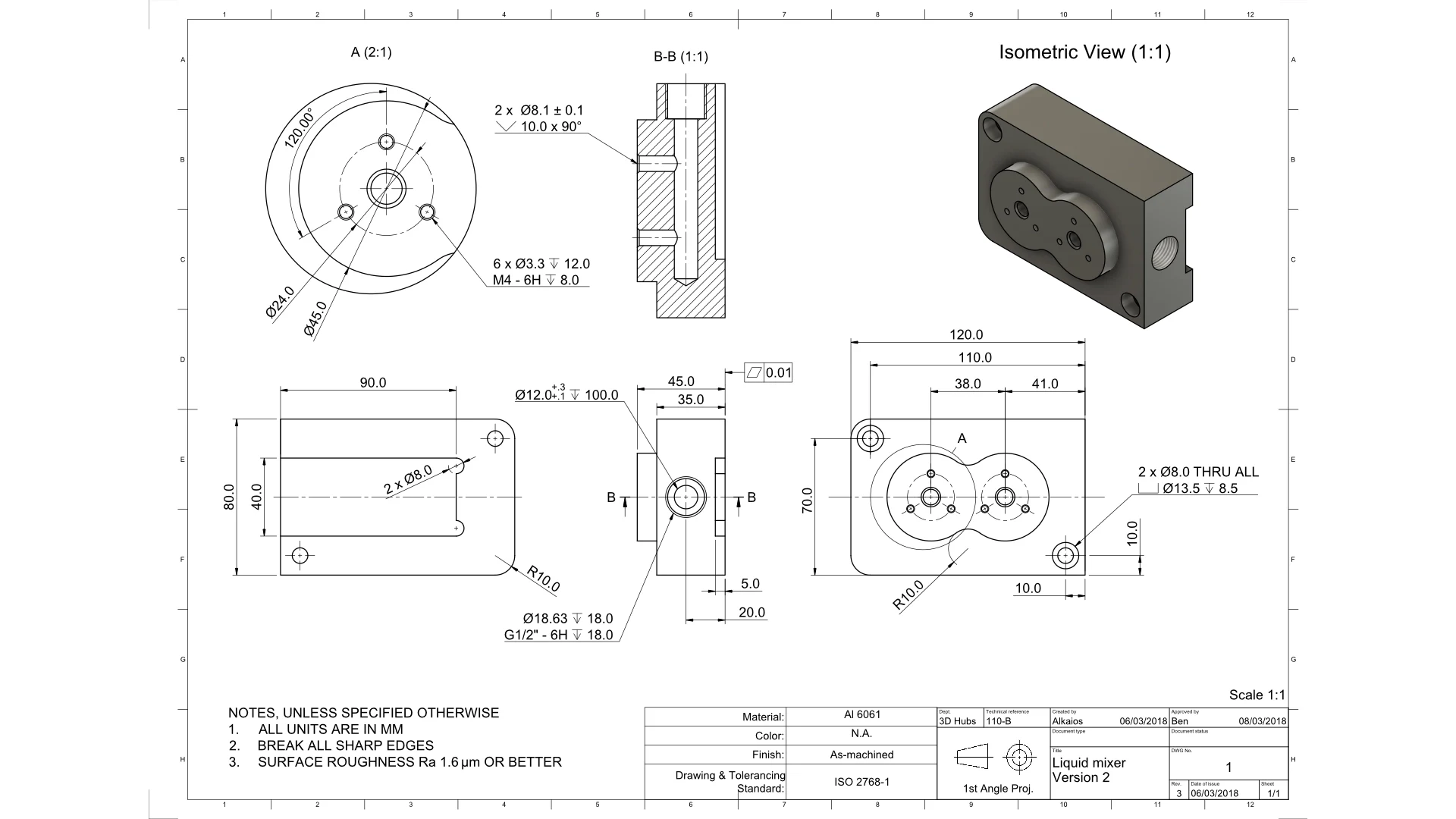
Provide the released model and drawing together when both govern, and resolve conflicts explicitly. Include material grade, applicable finish or treatment requirements, critical-section views, threads, datum definitions, and any inspection standard. If an MMC callout appears in a copied or supplier-created drawing, verify that its datum scheme still reflects the real assembly. This review is most effective before process planning, when clarification is less disruptive and acceptance criteria can still be aligned.
- List every feature control frame that uses MMC and identify its mating function.
- State whether actual feature size, bonus tolerance, and datum setup must appear on the report.
- Identify any required functional gauge, coordinate measurement output, first-piece review, or retained evidence.
- Resolve model-versus-drawing precedence and approval responsibilities before release.
Questions engineers ask
Does MMC make a geometric tolerance automatically larger?
No. Extra tolerance is available only when the applicable feature control frame uses an MMC modifier on the controlled feature and the measured feature departs from its MMC size. The governing drawing and standard control the calculation.
Can a go gauge replace all MMC inspection?
Not necessarily. A properly designed functional gauge can assess a defined functional boundary, but it may not verify separate requirements such as size, depth, surface condition, orientation, or reportable variable data. The drawing and inspection plan determine the needed evidence.
What should be supplied for an MMC inspection request?
Supply the current drawing revision, governing GD&T standard, model if applicable, material and process requirements, requested report fields, datum interpretation, sampling expectations, and any functional mating information. Clarify conflicts before manufacturing begins.
References and further reading
These resources explain related design and manufacturing principles. Project limits, acceptance criteria and process choices must be agreed against the current drawing.
Publication note: this article is general design guidance, not a material specification, a certified inspection report or a guarantee of process capability.
Turn the drawing into a clear manufacturing brief.
Share the current drawing, material, finish and inspection requirements for a project-specific discussion.