
Engineering article
Sink Marks in Injection Molded Parts
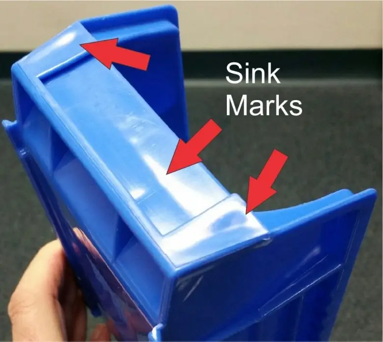
Sink marks in injection molded parts are surface depressions associated with uneven cooling and shrinkage, often around locally thick features. Their significance depends on function, appearance, material, surface specification, and viewing conditions. This guide frames sink control as a coordinated design, tooling, process-planning, and inspection decision rather than a universal process outcome.
On this page
What a sink mark indicates
A sink mark is a shallow surface depression that can appear when a thicker region cools and contracts after the surrounding skin has become relatively rigid. It is commonly associated with ribs, bosses, corner accumulations, inserts, or abrupt wall changes, but its appearance is not determined by geometry alone. Material behavior, mold temperature control, gate location, packing conditions, and surface texture also affect what is visible.
The engineering question is not simply whether a depression exists. It is whether the feature affects a sealing face, fit, dimension, visual requirement, coating behavior, or downstream assembly. A mark on a hidden internal wall may be acceptable under an agreed criterion, while a smaller mark in a customer-facing zone may require a different geometry or tooling approach. The drawing and acceptance standard should define that distinction.
Map thickness before refining details
The most productive first review is a thickness map, not a search for isolated cosmetic fixes. Trace nominal walls through corners, ribs, bosses, mounting pads, snap interfaces, and transitions to adjoining components. A feature that looks slender from one view can still create a concentrated mass where it joins the base wall. CAD section views and local wall-thickness analysis help expose these conditions early.
Where stiffness, fastening, or assembly location is needed, distribute material thoughtfully instead of accumulating it in one region. Open structures, cored bosses, gussets, and separated support features can preserve intent while reducing local thermal mass. The suitable form depends on load path, molding direction, draft, ejection, assembly forces, and the specified material grade. Those constraints should be resolved together, not one after another.
- Section the model through every rib-to-wall and boss-to-wall junction.
- Flag cosmetic surfaces opposite reinforced features.
- Review corners and overlaps for combined wall thickness.
- Confirm whether a local feature is structural, positional, or merely convenient.
Ribs and bosses need joint review
Ribs and bosses are useful because they can add stiffness, guide an assembly, or locate a fastener without making an entire part heavier. Yet each transfers material into a base wall, and its root geometry may influence the opposite show surface. A rib layout therefore needs simultaneous review for stiffness, draft, mold filling, venting, ejection, cosmetic sensitivity, and accessible tool construction.
For press or mating features, do not assume that adding material is the only route to retention. The mating-part tolerance scheme, insertion method, assembly load, temperature exposure, and material response may support alternative approaches. Small localized interference features can change how load is introduced, but they also require an engineering agreement on fit and durability. The final geometry should follow the application requirements and validated interface plan.
Tooling choices shape the risk
Gate position and flow path influence how effectively material can be packed while the gate remains available to transmit pressure. They also influence weld-line placement, filling balance, orientation effects, and cosmetic presentation. A preferred gate location for sink management may conflict with a visible gate vestige, a sensitive surface, or tooling access. These are quote-stage choices that benefit from marked cosmetic zones and a clear priority order.
Cooling layout, cavity construction, steel-safe provisions, and surface treatment can also change the practical response to a thick region. They should not be represented as independent remedies or guaranteed corrections. Tooling geometry and process window are developed around the approved part design, material grade, production intent, and visual standard. If the program permits iterative sampling, the decision record should state what observations would justify a design or tooling revision.
Surface finish changes visibility
A surface depression and a visible sink mark are related but not identical concerns. Gloss level, texture direction, color, lighting angle, part orientation, and inspection distance can make a small contour change conspicuous or difficult to detect. A highly reflective surface often reveals subtle changes differently from a textured surface. Surface finish should therefore be selected with both appearance intent and mold-release considerations in mind.
Do not use texture as an undocumented substitute for a cosmetic requirement. A texture can alter perception, but it may also affect cleanability, paint response, mating contact, dimensional measurement, and the visibility of other conditions. Specify the required finish or approved comparison standard, the applicable cosmetic area, and any restricted zones. If a recognized finish designation is used, its applicability should be confirmed against the material and tool plan.
Define inspection on the drawing
A useful drawing separates dimensional controls from appearance controls. Dimensions that govern assembly need datums, tolerances, and measurement conditions appropriate to their function. Cosmetic requirements need a defined viewing side, zone boundary, lighting or viewing convention where relevant, and an agreed acceptance reference. A statement such as “no sink marks” is usually too broad because it does not identify detection method, severity threshold, or functional consequence.
For a show surface, an approved sample, boundary sample, or documented visual standard can communicate more clearly than a subjective phrase. For functional surfaces, measurement may require a defined probe strategy, scan method, fixture, or section location. Inspection requirements should be realistic for production and should distinguish an allowable molded contour from a defect that compromises the agreed criterion. The controlling document is the drawing, specification, or engineering agreement.
- Mark Class A or equivalent cosmetic zones directly on the model or drawing.
- State the required surface finish and any allowed texture direction.
- Assign datums and tolerances to assembly-critical geometry.
- Name the inspection method when visual judgment alone is insufficient.
Compare response paths early
Sink-related decisions frequently involve a tradeoff rather than one correct adjustment. A geometry change may reduce local mass but alter stiffness or attachment options. A tooling or gating change may improve one region while moving evidence of flow or gate vestige elsewhere. A finish change may moderate visual perception but change the intended appearance. Comparing these paths before quote release makes the project assumptions visible and easier to review.
The table is qualitative. It does not replace material-specific analysis, molding trials, or the controls stated in the part documentation. Its purpose is to help a design team decide what must remain fixed and what may be evaluated during engineering review.
| Response path | Potential benefit | Primary tradeoff | Control document |
|---|---|---|---|
| Redistribute local material | May reduce concentrated shrinkage demand | Can change stiffness, load path, or assembly clearance | Approved CAD and structural requirements |
| Revise rib or boss architecture | May preserve function with less local mass | May affect draft, ejection, and tool complexity | Drawing, material grade, and tooling review |
| Adjust gate and process plan | May change packing access and flow behavior | May affect vestige, weld lines, or cycle assumptions | Process plan and cosmetic-zone agreement |
| Change finish strategy | May alter visual sensitivity | May alter appearance and surface function | Finish specification and approved visual standard |
Prepare the pre-quote package
A complete pre-quote package lets the engineering conversation focus on decisions rather than assumptions. Supply the current 3D model, controlled drawing, intended material grade, annual volume context if relevant, color and finish requirements, cosmetic-zone map, mating-part information, and critical functional conditions. Identify whether the part will be painted, plated, welded, assembled under load, or exposed to heat, chemicals, or light, since these factors can change the design priorities.
Ask for feedback on thickness concentrations, gate-access constraints, draft, ejection, parting-line implications, and inspection practicality. Where appearance is important, include representative viewing expectations and an acceptance route for early samples. Where a change could affect function, require written engineering disposition before release. This process does not guarantee the absence of sink; it establishes a disciplined basis for deciding what is acceptable and how it will be assessed.
- Provide a revision-controlled model and drawing.
- List the exact material grade, not only a material family.
- Map show surfaces and prohibited gate or ejector locations.
- Include mating parts, loads, and assembly sequence where they influence geometry.
- Agree how samples and visual acceptance will be reviewed.
Questions engineers ask
Can sink marks be eliminated by changing processing conditions?
Processing conditions can influence packing and cooling behavior, but they are not a universal correction for geometry-driven thickness concentrations. The feasible response depends on the material grade, gate access, tooling design, cosmetic requirement, and approved process plan. Review geometry and tooling assumptions before treating process adjustment as the primary solution.
Are sink marks only a cosmetic concern?
No. They may be principally cosmetic, but their importance depends on location and function. A surface depression can matter if it changes a sealing interface, clearance, flatness, assembly contact, or another controlled condition. The drawing and inspection plan should distinguish functional surfaces from appearance-only zones.
What should be sent for a sink-risk review before quotation?
Send the latest CAD model, controlled drawing, material grade, finish requirement, cosmetic-zone map, critical dimensions, mating-part details, and relevant assembly or service conditions. Include known priorities, such as preserving a show surface or a fastening interface, so geometry and tooling tradeoffs can be evaluated against the correct criteria.
References and further reading
These resources explain related design and manufacturing principles. Project limits, acceptance criteria and process choices must be agreed against the current drawing.
Publication note: this article is general design guidance, not a material specification, a certified inspection report or a guarantee of process capability.
Turn the drawing into a clear manufacturing brief.
Share the current drawing, material, finish and inspection requirements for a project-specific discussion.