
CNC Machined Bearing Housings, From Drawing to Inspection
Submit your drawing for DFM review, critical-dimension planning, and controlled machining of CNC machined bearing housings.
Representative Precision Component Work





Related Configurable Component Families and RFQ Support


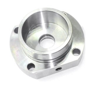



CNC Machined Bearing Housings: Engineering Advantages
A drawing-led workflow keeps functional interfaces, process decisions, and inspection expectations visible before production begins.
Drawing Review First
Review critical dimensions, materials, bearing-fit requirements, and application context before quotation so manufacturing assumptions can be resolved early.
Datum-Led Machining
Plan mounting faces, bearing bores, and locating features from clear datums to control relationships that affect assembly alignment.
Coordinated Process Routes
Select practical CNC, EDM, grinding, and fitting steps around feature access, stock allowance, surface requirements, and drawing priorities.
Inspection Planning
Define the inspection method and reporting needs around critical-to-quality features, rather than treating measurement as a final afterthought.
Revision Control
Keep drawing revisions, agreed manufacturing details, and project updates visible to reduce uncertainty when requirements change during production.
Traceable Communication
Coordinate material, quality, delivery, and documentation requirements through a clear project record aligned with the verified inspection plan.
Bearing Housings and Precision Component Families
Drawing-driven process routes for bearing-housing features, mold tooling, connector components, die parts, and controlled prototype or low-volume requirements.

CNC Machining Services
Precision CNC machining services for drawing-based bearing housings, flanges, mounts, and related custom parts. Review datums, bore relationships, wall sections, material, and inspection priorities before selecting milling, turning, EDM, grinding, or a combined process route.
Upload a Drawing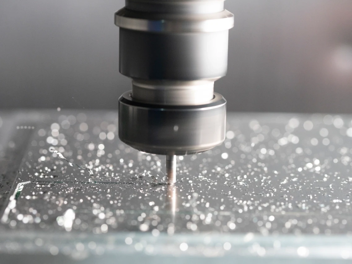
CNC Milling
Custom CNC milling services support prismatic bearing housings, mounting faces, bolt patterns, pockets, lubrication features, and locating geometry. Tool access, clamping strategy, datum transfer, and tolerance relationships should be reviewed against the drawing before production planning.
Upload a Drawing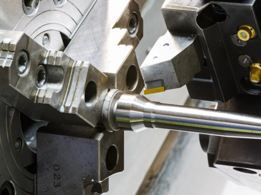
CNC Turning
Precision CNC turning services are suited to rotational bearing seats, sleeves, bushings, collars, flanges, and concentric interfaces. The process review considers bore-to-OD relationships, runout requirements, shoulder geometry, material condition, and whether grinding is needed after heat treatment.
Upload a Drawing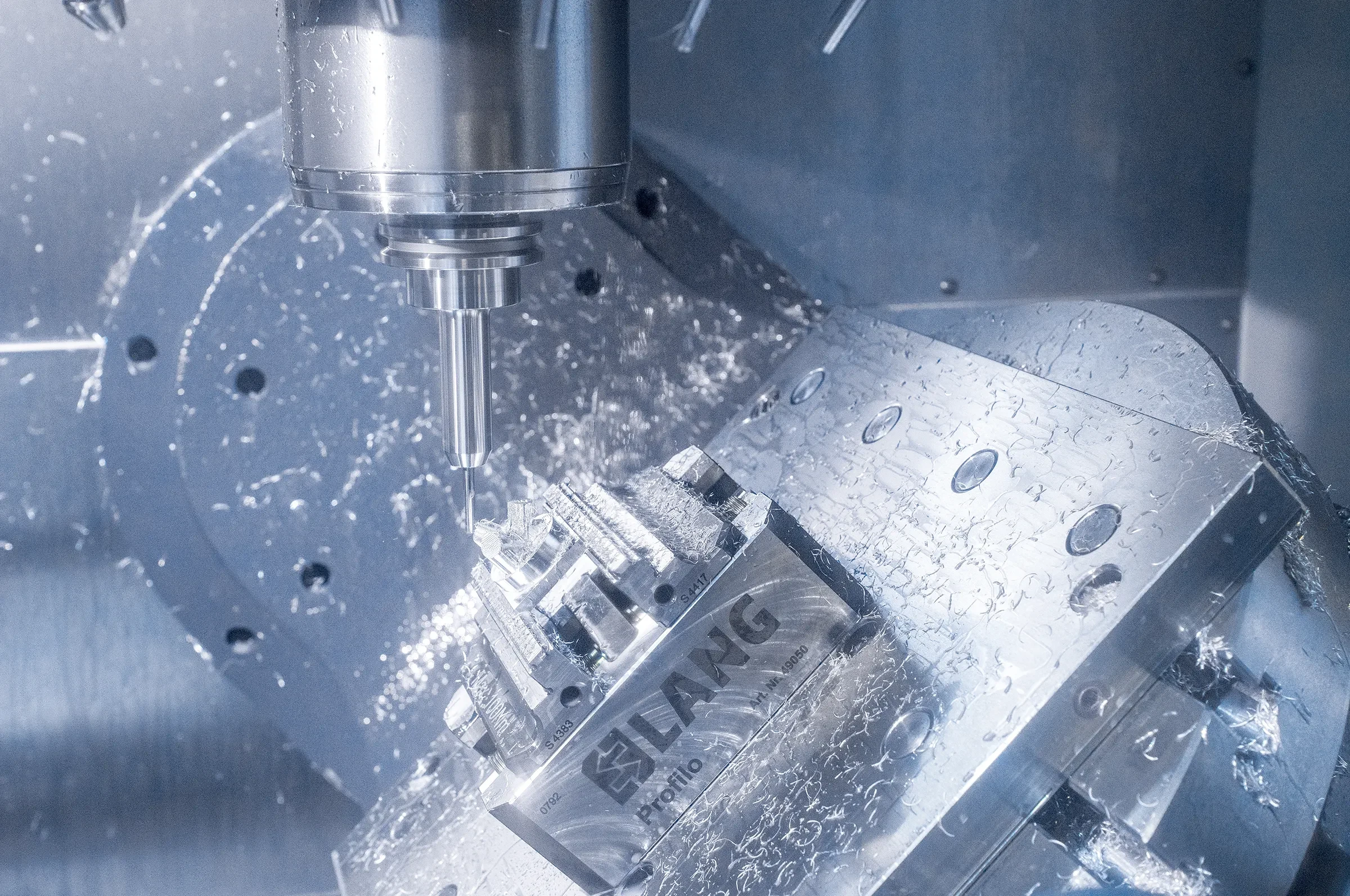
5-Axis Machining
5-axis CNC machining helps reach angled features, compound surfaces, and multiple faces with fewer repositioning steps. For complex bearing-housing geometry or tooling components, fixture access, cutter reach, datum control, and inspection access determine whether this route is appropriate.
Upload a Drawing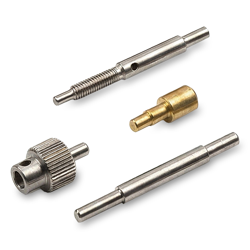
Swiss & Micro Machining
Swiss machining and micro machining support small, slender, or high-feature-density components where concentricity and handling matter. Typical requirements include miniature pins, shafts, sleeves, connector features, and small bearing-related parts, subject to drawing, material, and inspection review.
Upload a Drawing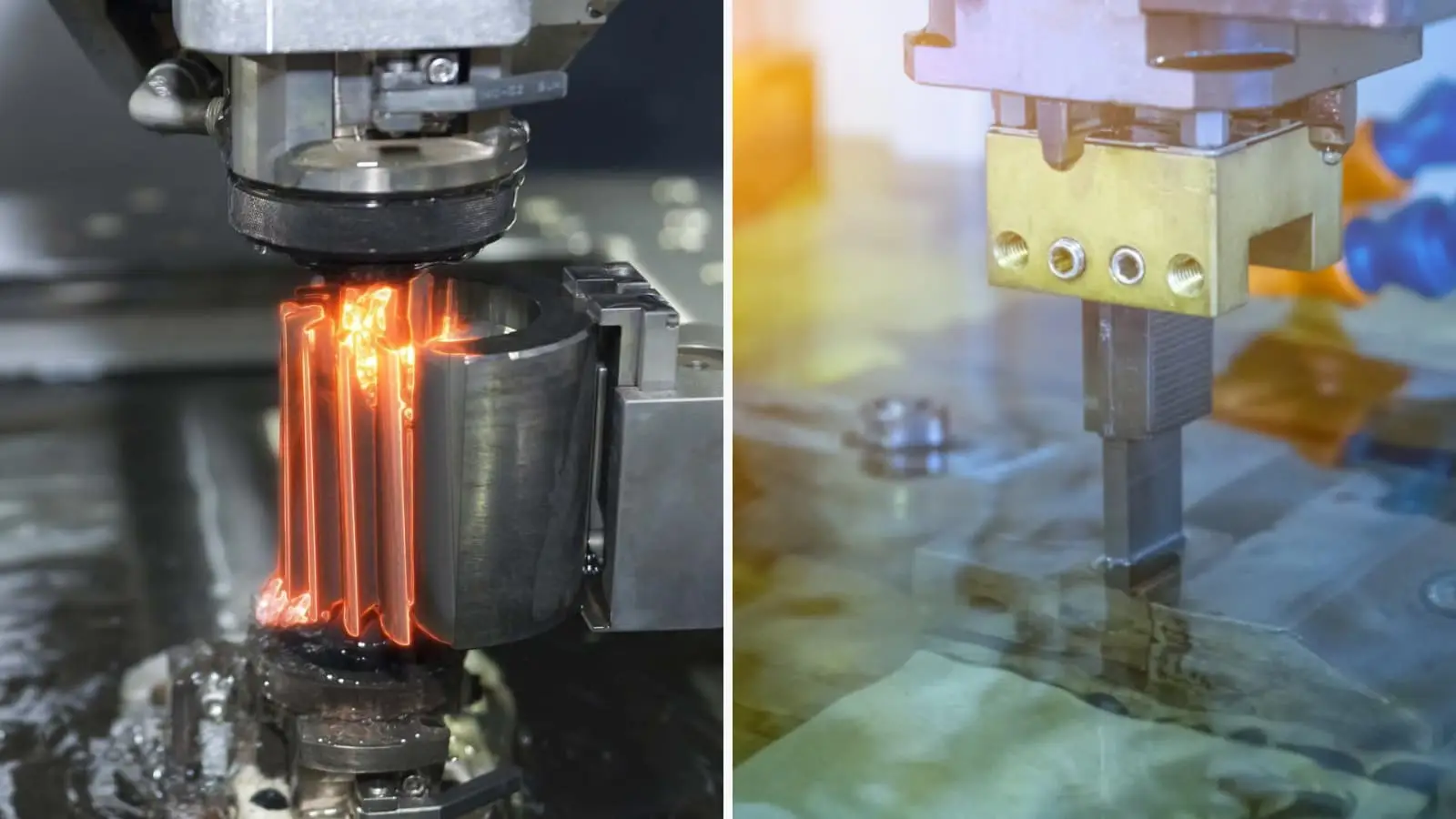
Wire & Sinker EDM
Wire EDM and sinker EDM services address hardened materials, narrow slots, internal corners, fine profiles, and shapes beyond conventional cutter access. Electrode strategy, wire path, finish requirements, recast-layer considerations, and subsequent fitting or polishing must be defined by the application.
Upload a Drawing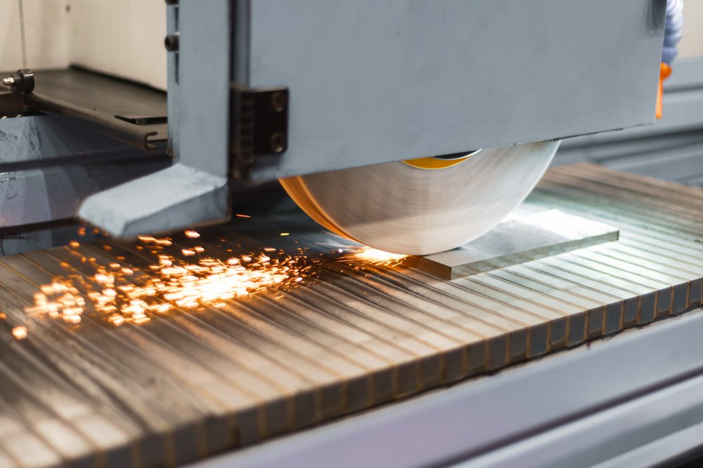
Precision Grinding
Precision surface and profile grinding provides controlled flatness, parallelism, profile accuracy, and finished bearing-seat or tooling surfaces. Grinding stock, heat-treatment sequence, datum condition, wheel access, and inspection method should be established before machining allowances are set.
Upload a Drawing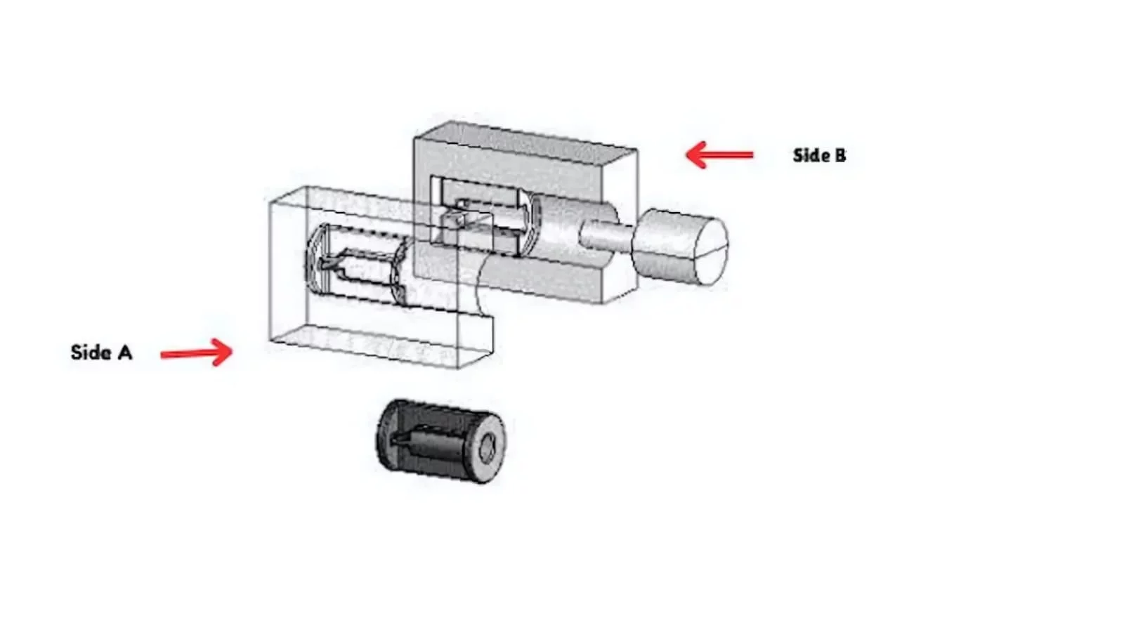
Mold Core & Cavity Inserts
Precision mold core and cavity inserts are configurable from drawings and mating requirements. Manufacturing planning considers steel selection, heat treatment, cooling or vent details, EDM access, shutoff conditions, fitting interfaces, and inspection of dimensions that affect molded-part quality.
Upload a Drawing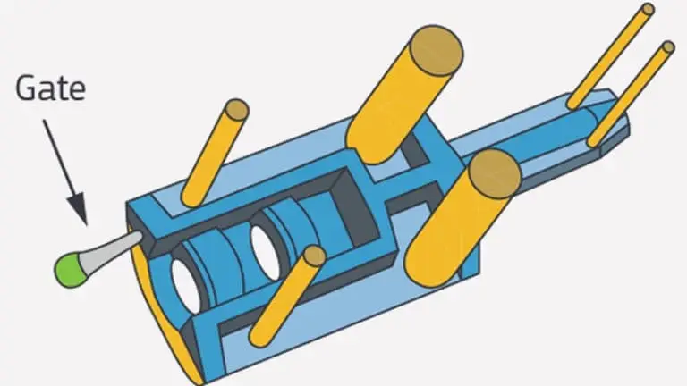
Ejector & Ejection Components
Ejector pins, sleeves, and ejection components are produced to fit the mold’s moving system and clearance requirements. Review pin diameter, guiding length, head form, material condition, lubrication context, surface condition, and the mating holes or plates before release.
Upload a Drawing
Core Pins, Guide & Locating Components
Core pins, guide pins, and locating components establish repeatable alignment between mold elements or assemblies. Critical decisions include fit class, straightness, concentricity, bearing or sliding surfaces, hardness sequence, datum references, and the dimensional relationship to corresponding holes and plates.
Upload a Drawing
Slides, Lifters, Gates & Mold Accessories
Mold slides, lifters, gates, and accessories are configured around part release, motion, sealing, wear, and assembly interfaces. Drawings should identify travel geometry, shutoff faces, contact conditions, cooling needs, material treatment, and inspection points for fitting-critical dimensions.
Upload a Drawing
Connector Mold Components
Precision connector mold components support fine-pitch, multi-cavity, and mating-feature tooling where small positional errors can affect molded connector performance. Process planning addresses micro features, electrode or wire-EDM needs, polishing, wear surfaces, datum strategy, and verification requirements.
Upload a Drawing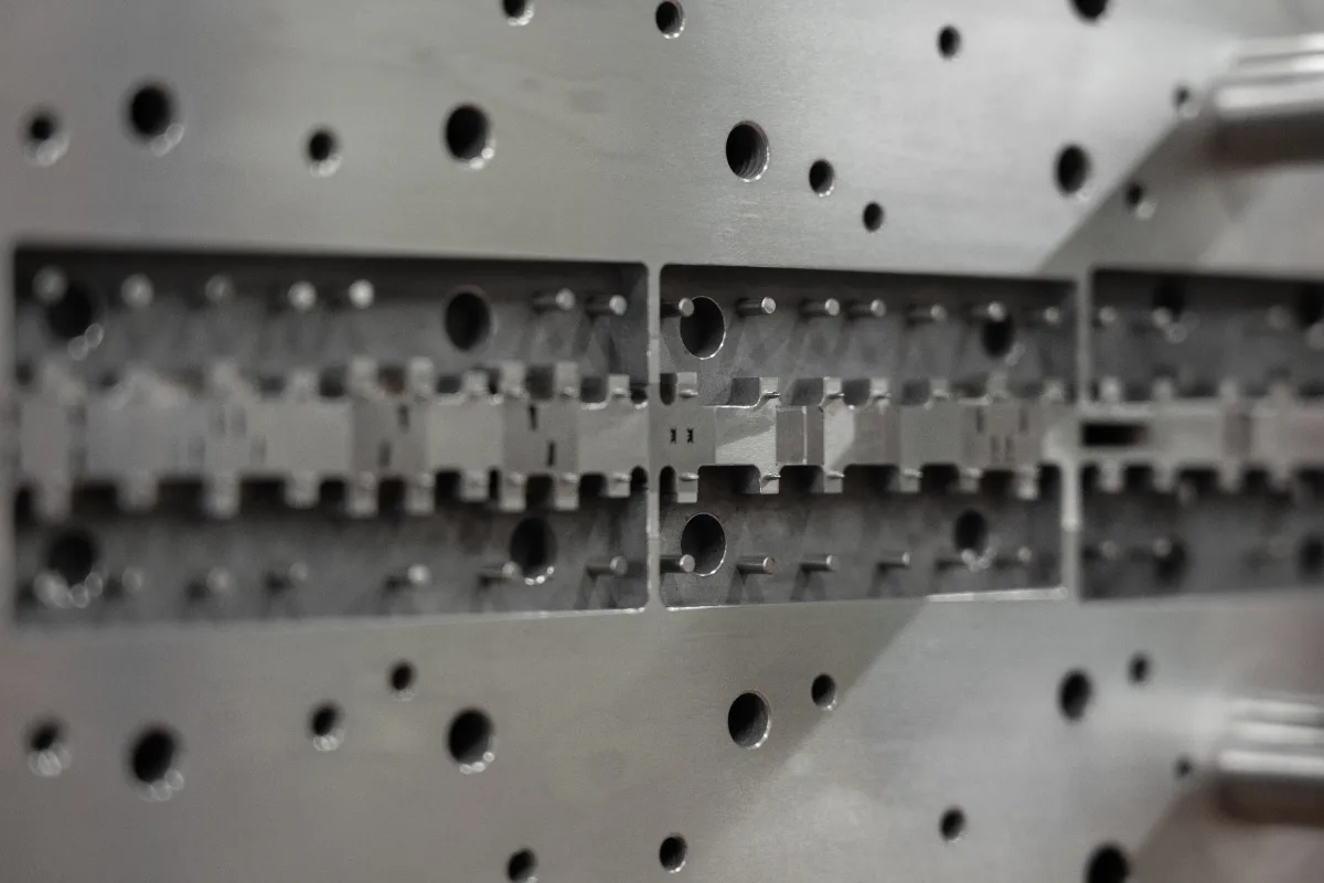
Stamping Die Components
Precision stamping die components include punches, dies, guides, plates, and forming elements made to drawing-defined geometry. Material, heat treatment, clearance relationships, wire-EDM profiles, grinding stock, edge condition, and assembly fit should be evaluated as one controlled tooling system.
Upload a Drawing
Injection, MIM, CIM & Overmolding Tooling
Injection, MIM, CIM, and overmolding tooling components are considered when requirements fall within verified production scope. Reviews focus on material flow interfaces, core and cavity details, inserts, gate or vent features, ejection, shrinkage context, and tooling-component inspection needs.
Upload a Drawing
Machining Materials
CNC machining materials are selected from the drawing, application, and downstream process requirements rather than assumed from appearance. Confirm material grade, condition, traceability expectations, corrosion or wear exposure, heat-treatment route, machinability, and any required material documentation before quotation.
Upload a Drawing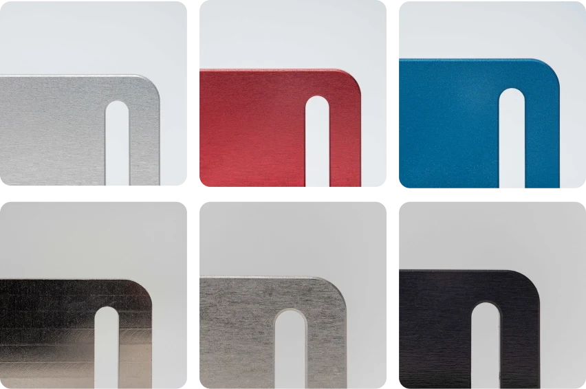
Surface Finishes & Heat Treatment
Surface finishing and heat treatment are planned around functional surfaces, corrosion resistance, wear, hardness, and dimensional change. Define coating or finish areas, masking needs, roughness targets, treatment sequence, post-treatment grinding allowance, and the evidence required for acceptance.
Upload a Drawing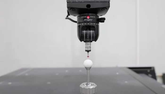
Quality, Metrology & Documentation
Precision inspection, metrology, and quality documentation should follow the order-specific inspection plan. Identify critical dimensions, datums, measurement methods, sampling expectations, report format, revision status, material evidence, and any packaging or traceability requirements before production begins.
Upload a Drawing
Prototyping & Low-Volume Production
Rapid prototyping and low-volume manufacturing support design validation, bridge needs, replacement components, and controlled pre-production work. Provide the current drawing or model, material, quantity, functional interfaces, critical dimensions, inspection expectations, and target delivery date for a viable process review.
Upload a DrawingMaterials for CNC Machined Bearing Housings
Aluminum Alloys
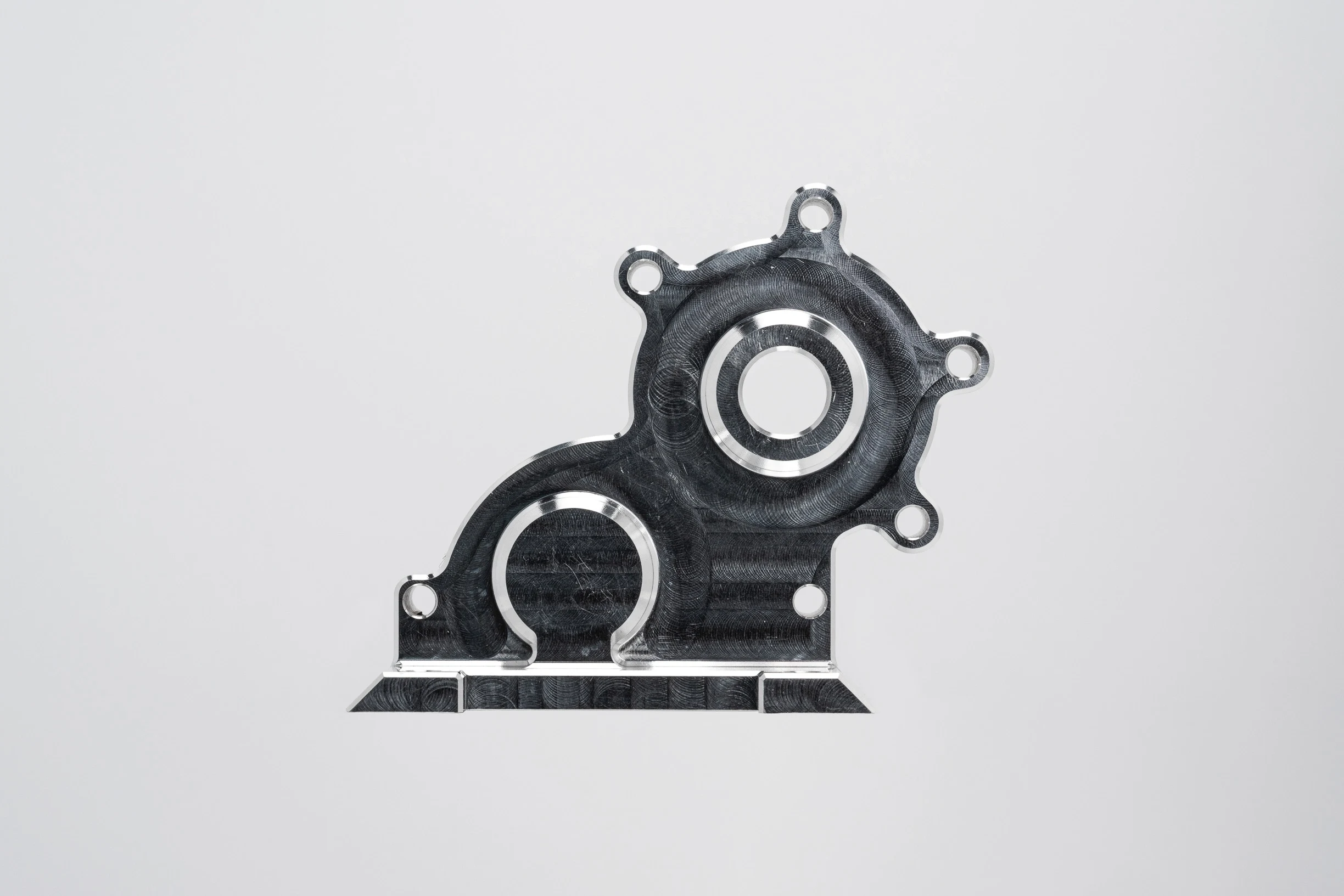
Often evaluated for weight-sensitive housings and corrosion-conscious equipment. Alloy choice, section thickness, thread loading, bearing-seat requirements, and surface treatment must be reviewed against the drawing and application conditions.
Carbon Alloy Steels
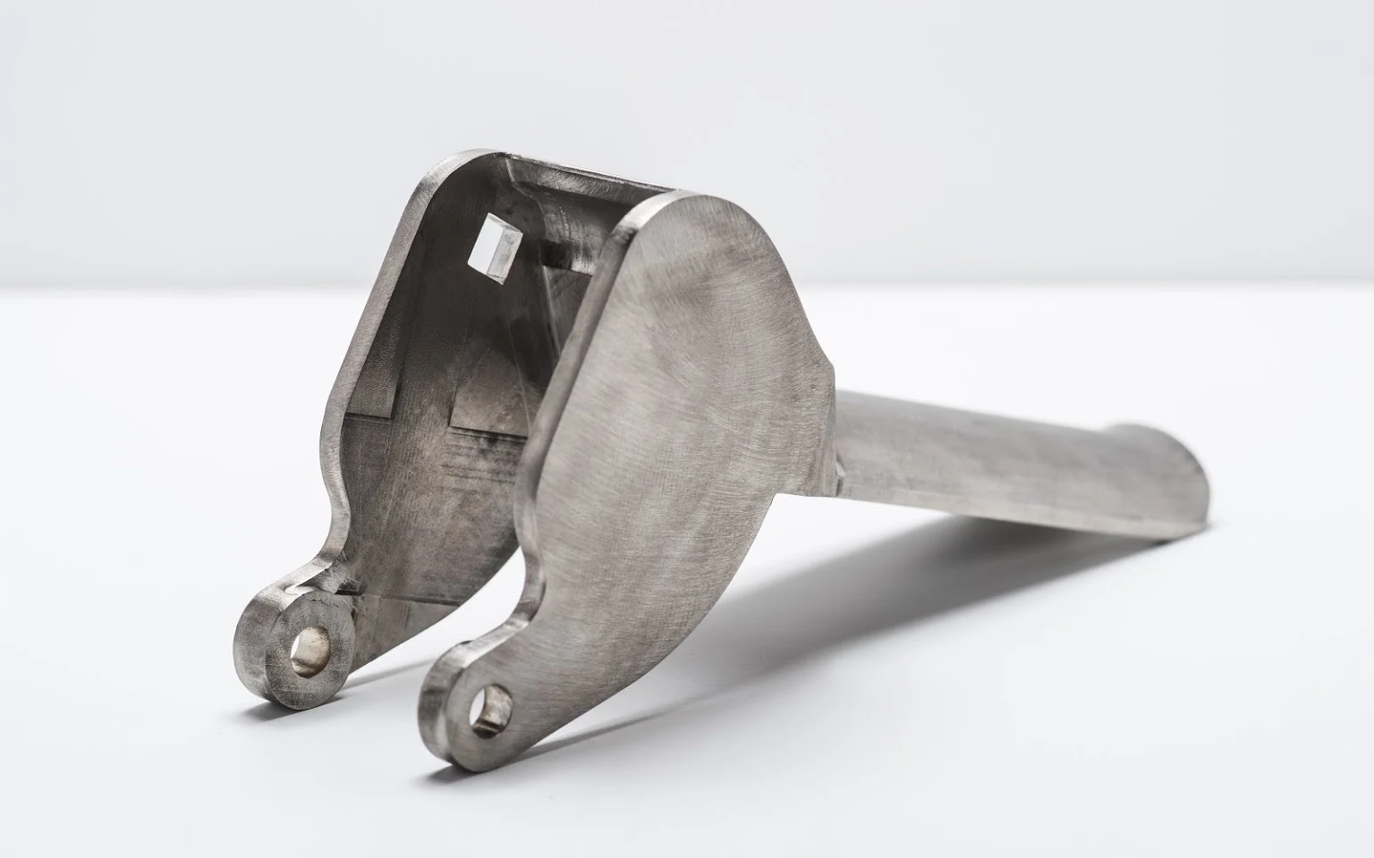
Considered where structural loading, wear resistance, or heat-treatment requirements influence the housing design. Material condition, machining allowance, stress relief, and the sequence of bore finishing require project-specific review.
Stainless Steel Grades
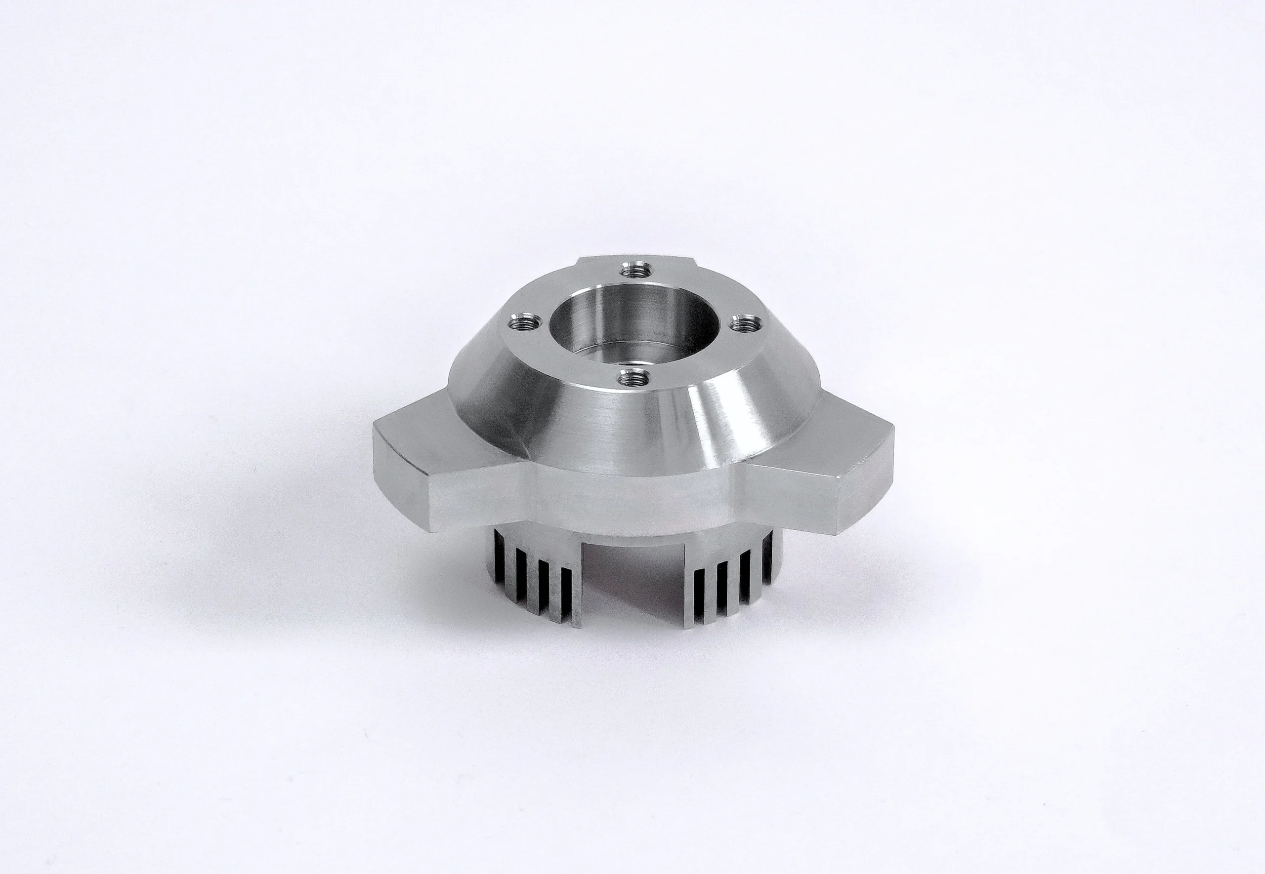
May suit applications where corrosion exposure, cleanliness, or material compatibility is important. Grade selection should account for machining behavior, required surface condition, bearing interface details, and any specified inspection documentation.
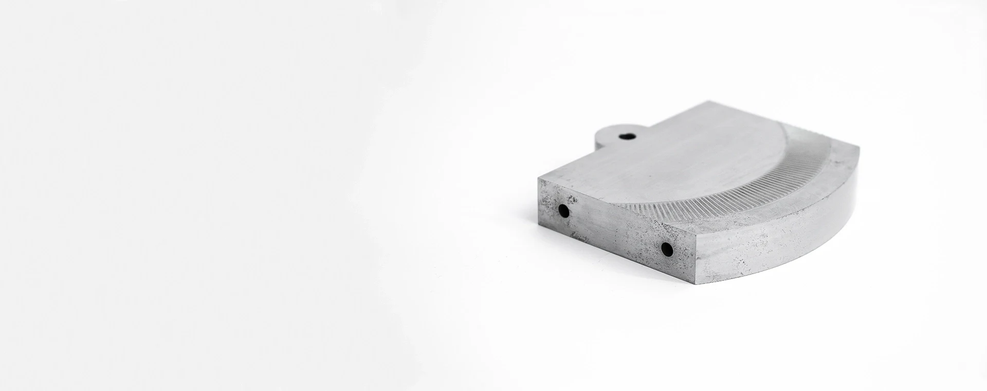
Tool Steel Grades
Used selectively when a drawing calls for elevated hardness, wear performance, or controlled thermal treatment. The machining route should define grinding stock, EDM needs, heat-treatment timing, and critical-dimension inspection methods.
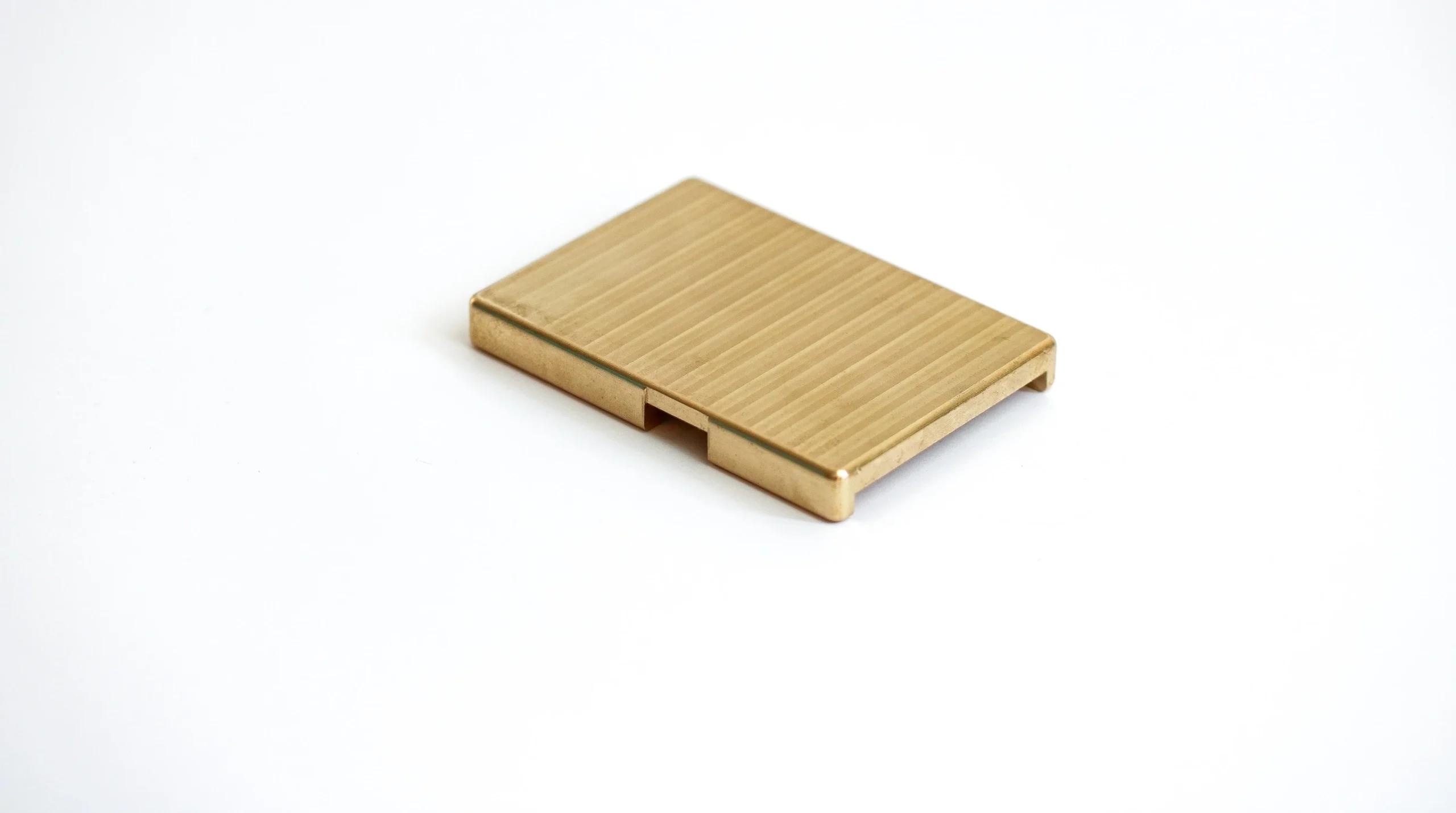
Engineering Brass Alloys
Can be evaluated for specialized assemblies requiring machinability, corrosion behavior, or compatibility with mating components. Final selection depends on the specified grade, functional loads, geometry, finish requirements, and project evidence.
CNC Machined Bearing Housings: Process Options for Critical Features
CNC Milling
CNC milling establishes mounting faces, pockets, bolt patterns and external profiles. Fixture strategy and cutter access are reviewed against the primary datum so functional surfaces can be related to the bearing-seat machining plan.
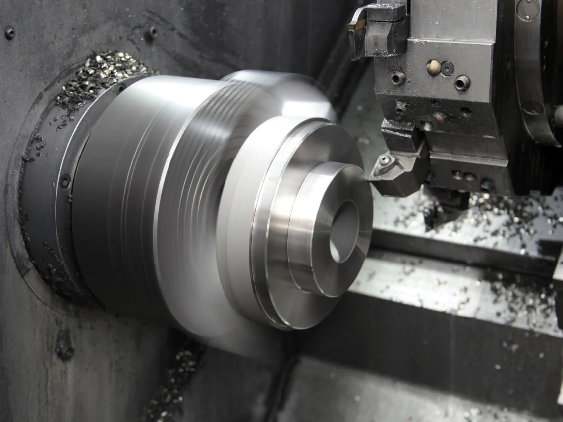
CNC Turning
CNC turning suits rotational features such as concentric diameters, pilots and cylindrical bearing-seat regions. It helps define a stable reference for parts whose critical geometry is best controlled around a common axis.
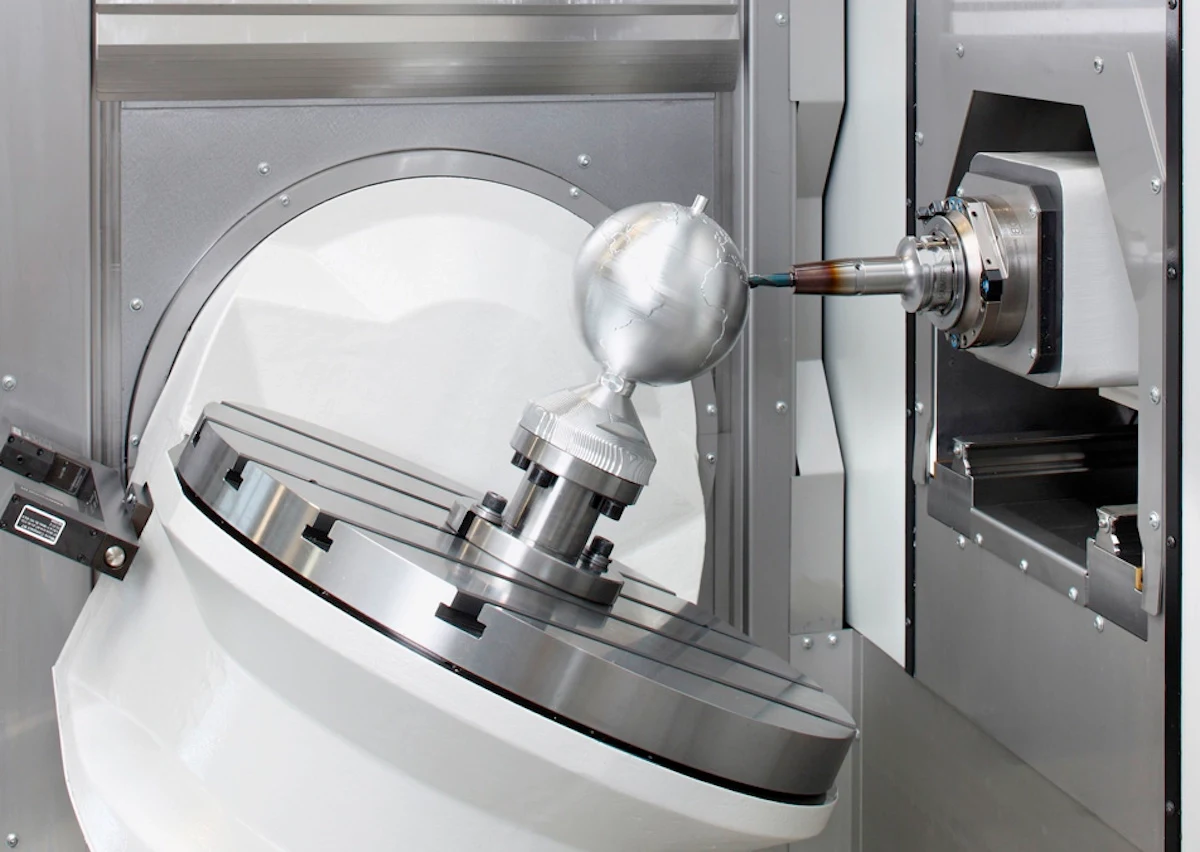
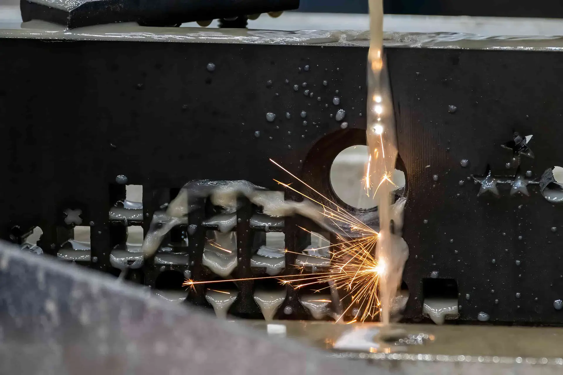
Wire EDM
Wire EDM is considered for narrow slots, sharp internal profiles and hardened features where conventional cutter access is restricted. Wire-path planning, start-hole access and the allowable corner condition should be defined during drawing review.
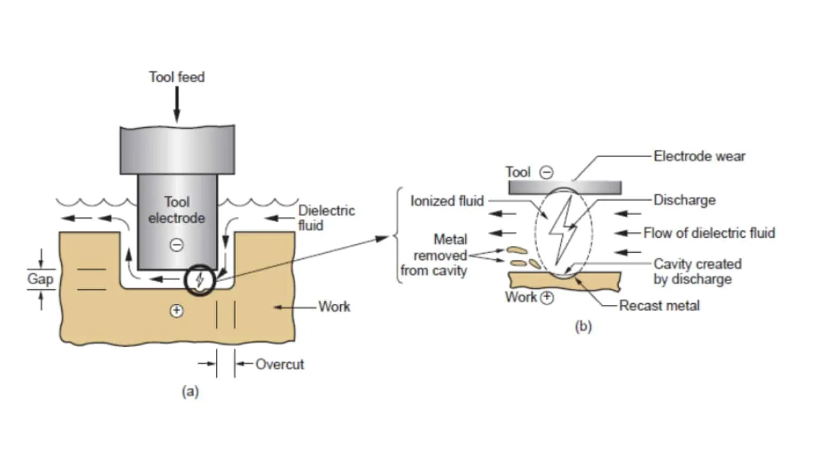
Sinker EDM
Sinker EDM supports enclosed cavities, deep details and feature geometry that cannot be reached reliably with a rotating tool. Electrode design, flushing access, finish requirements and subsequent inspection points require early agreement.

Precision Grinding
Precision grinding refines selected bearing-related faces, locating surfaces and controlled dimensions after the appropriate machining or heat-treatment sequence. Grinding stock, datum protection and measurement method should be specified before the route is released.
Supporting Features for CNC Machined Bearing Housings
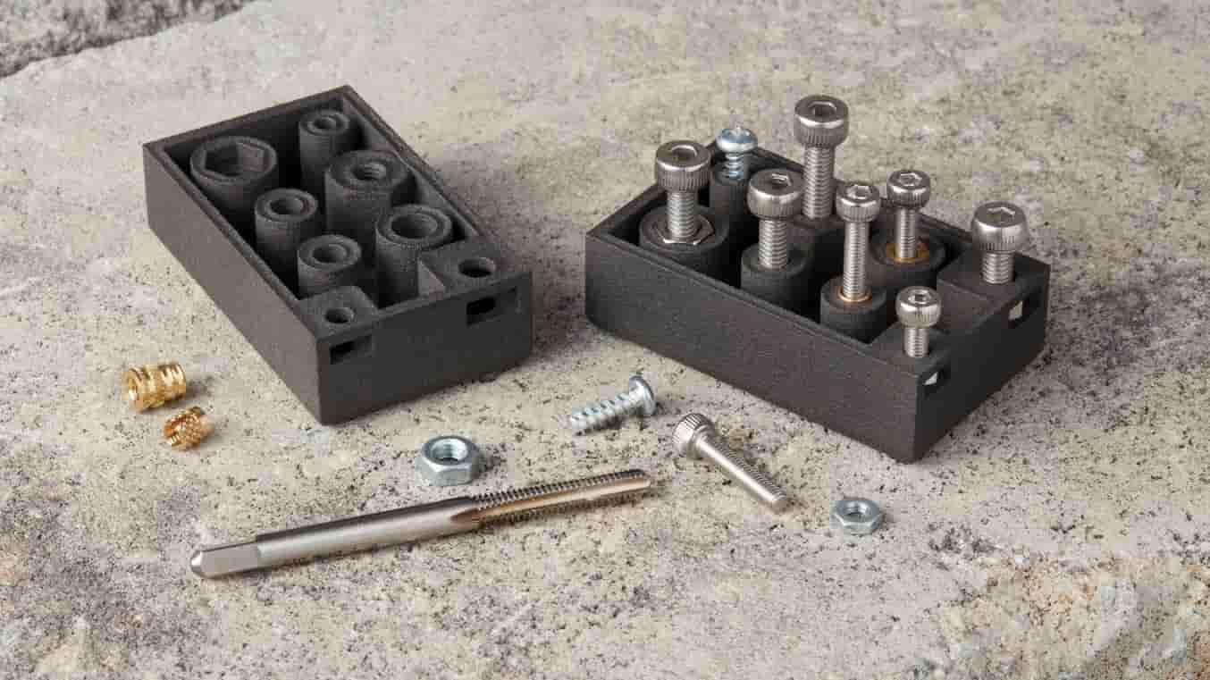
Threaded Features
Tapped holes, threaded ports, and retaining-thread details can be incorporated where mounting, lubrication, covers, or sensor attachments require them. Call out thread standard, depth, engagement, datum relationship, and any post-treatment masking requirements.

Locating Elements
Dowel holes, locating pilots, shoulders, and register diameters help establish repeatable assembly position. For CNC machined bearing housings, identify the mating component, fit intent, datum scheme, and whether installation hardware is customer supplied.

Sealing Interfaces
Seal bores, gland grooves, cover registers, and gasket faces can be planned around the specified sealing concept. Provide seal type, mating dimensions, surface requirements, and assembly orientation so machining access and inspection points can be reviewed.

Fastener Provisions
Clearance holes, counterbores, countersinks, tapped mounting points, and captive-fastener features can be added to suit the assembly drawing. Define fastener standard, head clearance, tightening access, hole pattern datum, and any required anti-rotation detail.
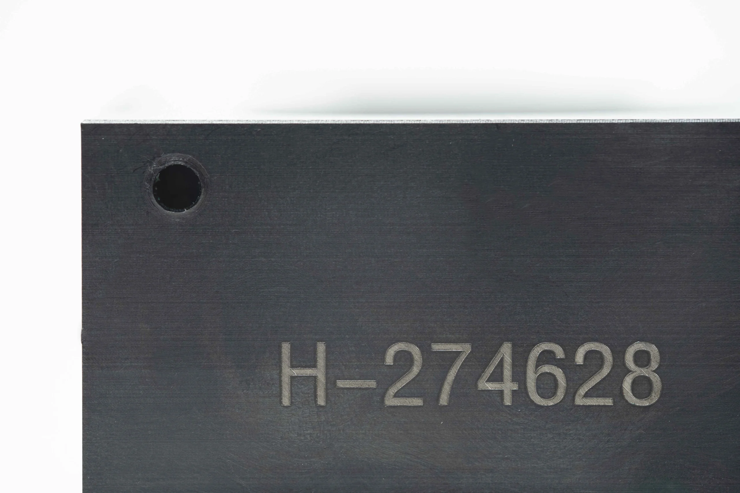
Part Identification
Part marks, revision identifiers, controlled labels, protective packaging, and inspection-report requirements can be coordinated for drawing-based orders. State marking location, readable format, traceability needs, packaging protection, and documentation required with shipment.
About SUUXIANG Precision Manufacturing
SUUXIANG is the international-facing brand of Dongguan SuuXiang Precision Mold Co., Ltd., established in 2010 in Chang’an Town, Dongguan, Guangdong, China. We help global engineering, sourcing, and quality teams convert drawings and specifications into inspected custom CNC parts, precision mold components, connector tooling, and die components.
For cnc machined bearing housings and other drawing-based parts, our planning brings together CNC milling and turning, multi-axis machining, EDM, precision grinding, fitting, and inspection. Before quotation or production commitments, we review critical dimensions, datums, material and heat-treatment requirements, machining access, surface needs, and inspection expectations.
Our difference is disciplined project control: process choices follow functional requirements rather than a generic route. SUUXIANG keeps revision, inspection, and delivery information visible throughout the work, helping buyers evaluate manufacturability, manage assembly risk, and receive documentation aligned with the agreed inspection plan.

How SUUXIANG Builds CNC Machined Bearing Housings
Start With Functional Datums
SUUXIANG reviews the drawing around the bearing seat, mounting face, locating features, and mating relationships before quotation. The discussion identifies functional datums and critical dimensions so the machining route supports assembly alignment instead of treating each tolerance as an isolated requirement.
- Confirm the bearing bore fit and datum references
- Relate mounting faces, pilots, and hole patterns
- Flag tolerance-stack and tool-access risks early
- Align 2D drawing, 3D model, and revision status

Sequence Critical Features Carefully
For cnc machined bearing housings, process order affects the relationship between the bore, mounting interfaces, and locating details. SUUXIANG plans CNC milling, turning, multi-axis work, or secondary operations around clamping stability, accessible references, material condition, and the drawing’s functional priorities.
- Establish stable clamping and usable machining datums
- Machine bore, face, and location features in controlled relationships
- Consider heat-treatment sequence where specified
- Keep process decisions tied to drawing requirements

Use EDM and Grinding Purposefully
Complex internal forms, hardened areas, fine corners, or demanding finish requirements may call for EDM or precision grinding after primary machining. SUUXIANG evaluates electrode access, wire path, grinding stock, and distortion risk so secondary processes address specific functional requirements rather than add unnecessary operations.
- Review wire-EDM access for enclosed or narrow features
- Plan electrode strategy for difficult internal geometry
- Reserve appropriate grinding allowance where required
- Consider material condition before final finishing
Plan Inspection Around Assembly
Inspection planning for cnc machined bearing housings begins with the features that determine fit and alignment. SUUXIANG aligns measurement methods, reporting needs, and traceability expectations with the order’s verified inspection plan, including critical bores, datum-related positions, mounting faces, and revision-controlled documentation.
- Define critical-to-quality features before production
- Match inspection methods to the drawing and order
- Confirm reporting and traceability expectations
- Keep final documentation aligned with the verified plan
Why Choose SUUXIANG for CNC Machined Bearing Housings
A disciplined drawing-to-inspection workflow helps teams evaluate manufacturing readiness before production commitments.
← Swipe left or right to view →
CNC Machined Bearing Housings: From Drawing Review to Delivery
A drawing-led workflow keeps critical interfaces, inspection requirements, revisions and delivery details visible before production commitments are made.
Review RFQ Inputs
We review drawings, models, material, quantity, application context, target date, and inspection needs, identifying bearing bores, mounting faces, datums, and other critical dimensions.
Plan Manufacturing Route
DFM discussion confirms tool access, setup strategy, machining allowance, heat-treatment sequence, EDM or grinding needs, and practical inspection methods before quotation and release.
Machine Critical Features
Approved CNC milling, turning, multi-axis machining, EDM, and grinding operations are coordinated according to the documented process route and controlled revision.
Complete Secondary Operations
Where specified, fitting, deburring, surface preparation, and related secondary work are planned around critical interfaces so handling does not compromise functional features.
Inspect and Document
Finished parts are checked against the agreed drawing and inspection plan, with applicable measurements and documentation aligned to the order requirements.
Pack and Coordinate Delivery
Parts are protected for shipment, identified to support traceability, and prepared with agreed documentation while delivery coordination remains visible to the project team.
How to Work With SUUXIANG on CNC Machined Bearing Housings
Bring the drawing, application priorities, and quality requirements into the discussion early so the manufacturing route and documentation can be aligned before release.
Submit Your Drawing Package
Provide 2D drawings, available 3D models, material, quantity, delivery target, and bearing-fit or assembly notes for an informed initial review.
Review Critical Requirements
Align critical dimensions, datums, surface requirements, machining access, heat-treatment sequence, inspection needs, and any sampling or revision-control expectations before quotation.
Confirm the Production Plan
Review the proposed process route for CNC machining, EDM, grinding, fitting, and inspection; approve clarified specifications before production commitments are released.
Receive Coordinated Delivery
SUUXIANG coordinates production status, revision visibility, final inspection documentation, and delivery information according to the confirmed order and inspection plan.
Customer Feedback on CNC Machined Bearing Housings
Approved customer testimonial pending verification of project scope, measurable outcome, and permission to publish attributable feedback for a CNC machined bearing housing program.
Approved customer testimonial pending verification of drawing-review findings, inspection requirements, and a documented production outcome for CNC machined bearing housings.
Approved customer testimonial pending verification of revision-control, delivery, and assembly-related results for a drawing-based CNC machined bearing housing order.
CNC Machined Bearing Housings FAQ
Practical RFQ, quality, delivery and revision-control questions for drawing-based bearing housing projects.
What information should I provide for cnc machined bearing housings?
Can you quote cnc machined bearing housings from a drawing?
Is there a minimum order quantity for cnc machined bearing housings?
Can I request a first article or sample before a production order?
Which materials and heat treatments can be considered for bearing housings?
What inspection reports can be supplied with cnc machined bearing housings?
How are lead time, shipping, payment, and design revisions handled?
The Complete Buyer’s Guide to cnc machined bearing housings
Use this decision framework to specify functional fits, compare materials and manufacturing routes, evaluate drawing-based suppliers, control total cost, and avoid sourcing mistakes that compromise bearing alignment, assembly performance, or program timing.
1. What Are cnc machined bearing housings?
One cnc machined bearing housing is a drawing-defined component that locates and retains a rolling bearing while transferring bearing reactions into the mounting structure. Its bore, shoulder or retaining feature establishes the bearing’s radial and axial position; the bearing then supports the shaft, so bore geometry and shaft-axis relationship affect running clearance, preload, and alignment.
Two datum relationships normally govern the functional drawing: the bearing-seat axis to the mounting face, and the mounting holes or locating pilot to that same axis. The buyer should identify which faces establish assembly position, which feature controls axial retention, and which dimensions are critical to the mating shaft, frame, or gearbox rather than applying tight tolerances everywhere.
A catalog housed-bearing unit combines a standard bearing and standardized pedestal, flange, or cartridge housing. Specify a custom housing when the assembly needs nonstandard mounting geometry, a defined datum scheme, integration with adjacent components, a particular material or sealing arrangement, or a controlled replacement interface; submit the bearing designation, shaft details, mating geometry, loads, environment, and inspection requirements with the RFQ.
2. Evolution of cnc machined bearing housings
2D drawings and catalog envelope dimensions once pushed many bearing housings toward standardized units, cast bodies, or welded fabrications with only the bore, mounting faces, and holes finish-machined. For one-offs and low quantities, direct machining from stock avoids creating a casting pattern and accommodates drawing changes more readily. https://www.wengdinengineering.com/custom-bearing-housing
3-axis milling expanded the range of custom mounting patterns, pockets, and datum-related faces that could be made directly from CAD/CAM data; turning retained an efficient role for coaxial bores, pilots, and cylindrical features. Multi-axis access further reduced re-clamping on suitable geometries, helping designers relate features within a controlled setup rather than adapting every design to a catalog housing.
CMM-based dimensional inspection, bore measurement, and documented datum schemes changed the buyer conversation from nominal geometry to verified functional relationships. A modern drawing package can therefore define a prototype or precision assembly housing around its mating shaft, bearing fit, seals, and mounting interface, while the supplier reviews tool access, stock removal, and inspection method before selecting a fully machined or CNC-finished route.
3. Types of cnc machined bearing housings
Configuration should follow the load path, mounting datum, and replacement procedure—not merely the available envelope. For cnc machined bearing housings, define how the bearing is retained and accessed before releasing the drawing.
Pillow-Block And Pedestal Forms
Pillow-block housings mount on a horizontal base and carry radial load into the machine bed.
Pedestal height improves shaft clearance, but increases overturning moment; use shoulder, cover, or retainer-ring features for axial retention.
Flanged Housings
Flanged housings bolt to a vertical or end-face mounting plane, aligning the shaft normal to that face.
A machined bore shoulder locates the outer ring; a cover or circlip enables service without disturbing the parent structure.
Cartridge And Insert Housings
Cartridge housings place a removable bearing module into a parent bore, usually along the shaft axis.
A flange, shoulder, or threaded retainer controls insertion depth; the trade-off is added interfaces and tighter concentricity requirements.
Split Housings
Split housings divide at the bearing centerline, allowing bearing replacement without removing a long shaft.
Dowelled joint faces preserve cap-to-base location, while bolts supply clamp load; sealing and joint rigidity require careful design.
Integrated Structure Housings
Integrated housings machine the bearing seat directly into a frame, gearbox wall, or machine plate.
This approach minimizes interfaces and can improve datum control, but bearing replacement may require larger assembly disassembly.
4. Materials for cnc machined bearing housings
Material choice for cnc machined bearing housings begins with radial and axial load, bearing-seat fit, operating temperature, and exposure. Mass targets and mating-shaft material then determine whether stiffness, corrosion resistance, or thermal compatibility governs.
| Material Family | Key Strength | Primary Limitation | Typical Finish Direction |
|---|---|---|---|
| Aluminum alloy | Low mass; good machinability | Lower stiffness and seat wear | Anodizing or paint |
| Carbon/alloy steel | High stiffness and load capacity | Needs corrosion control | Black oxide, plating, or paint |
| Stainless steel | Corrosion resistance | Harder machining; higher mass | Passivation or specified finish |
| Brass/bronze | Corrosion resistance; bearing compatibility | Lower structural strength | Often machined finish |
| Engineering polymer | Low mass; chemical resistance | Creep and thermal expansion | Usually uncoated |
Compare Structural Materials
Aluminum alloys reduce mass and machine efficiently, but provide lower stiffness and wear resistance than steel.
Carbon and alloy steels suit high-load, rigid housings when corrosion protection and finishing are specified.
Match Environment And Finish
Stainless steels suit wet or corrosive service, with grade selection tied to the actual medium and temperature.
Brass or bronze can suit corrosion-resistant, low-friction interfaces, but should not replace a load-path review.
Check Fit And Temperature
Engineering polymers are appropriate only for light-duty, chemically resistant, or electrically isolating housings.
Differential thermal expansion can alter bearing-seat retention; confirm the housing, bearing outer ring, shaft, and coating stack together.
5. Custom options for cnc machined bearing housings
Two interfaces drive functional customization: the bearing seat and the machine mount. Specify these features on the drawing before selecting a protective finish for cnc machined bearing housings.
| Option | Typical Purpose | Fit-Control Note |
|---|---|---|
| Anodizing | Aluminum corrosion protection | Mask seat and pilot |
| Passivation | Stainless cleaning | No dimensional buildup |
| Plating | Corrosion or conductivity | Define thickness and masking |
| Paint or powder coat | External protection | Exclude functional fits |
Bore And Retention
Three bore controls are seat diameter, shoulder position, and retention method. State fit from the bearing manufacturer’s data.
One circlip groove or end cover needs an axial datum. Keep lead-in chamfers outside the effective seat length.
Mounting And Service Features
Four mounting controls are hole pattern, face datum, pilot diameter, and dowel location. Locating pilots prevent bolts with clearance holes from setting final position.
One lubrication path may use a drilled gallery, fitting thread, or relief port. Reserve defined pockets or threads for seals and sensors.
Identification And Protective Finishes
One engraved part number and revision code can preserve assembly traceability. Place marking away from sealing lands and critical stress areas.
Five finish options require fit review before release. Mask bearing seats, pilots, threads, and mounting datums whenever coating buildup could change function.
6. Critical construction and quality elements
The bearing seat, mounting interfaces, and datum scheme govern how a housing locates the bearing and transfers load. Assign tighter requirements only to interfaces that affect fit, alignment, sealing, or mating assembly.
Functional Datum Strategy
A primary mounting face, secondary locating feature, and tertiary clocking feature should reflect the installed assembly. Dimension the seat bore and mounting holes from these datums rather than chaining dimensions across nonfunctional edges.
Seat And Mounting Geometry
The bearing-seat diameter, roundness, and cylinder geometry should match the bearing fit and retention intent stated on the drawing. Control concentricity or position between the bore, shaft-related features, and locating pilots where runout affects the application.
Mounting-face flatness and hole location need tolerances based on the mating structure. Include wall thickness, fillet radii, tool access, and assembly clearance in DFM review so clamping and machining do not compromise stiffness or reach.
Inspection Plan
A drawing-based inspection plan should identify CTQ bore, face, and hole relationships; the measurement method must suit the tolerance and datum setup. Visual inspection should also address burrs, sharp edges, damage, cleanliness, and inaccessible deburring areas.
Application-specific verification—such as trial assembly, leak testing, or runout checks—should be agreed before release. SUUXIANG can align final records with the order-specific inspection plan and revision-controlled drawing.
7. Choosing a bearing-housing manufacturer
A capable supplier evaluates cnc machined bearing housings from the drawing outward, not from a generic tolerance claim. Require evidence that the proposed route protects bearing-seat relationships, datum references, and delivery commitments.
Test DFM Responsiveness
The RFQ should include a 2D drawing, 3D model, quantity, material, heat treatment, critical fits, and mating-part context. Ask which features need milling, turning, grinding, or EDM, and which datum controls each setup.
- What feature drives the first fixture?
- Which tolerance needs a special inspection method?
- What design issue could delay release?
Verify Material And Process Control
Material traceability should match the order requirement, including grade, condition, and any specified heat-treatment record. Cylindrical seats may favor turning; prismatic mounting faces and cross-features usually require milling, with the fixture plan explaining how concentricity is retained.
Confirm Production Communication
Prototype and low-volume orders need a named revision, inspection plan, packaging method, and realistic lead-time breakdown before release. Ask how changes are acknowledged, how nonconforming dimensions are reported, and whether final documentation follows the approved drawing revision.
8. Common buyer mistakes to avoid
Most avoidable bearing-housing failures begin before machining: the drawing omits functional context or delays quality decisions. Resolve these items during drawing review, before material is ordered or programs are released.
Define Fits And Datums
A bearing bore tolerance without bearing series, fit intent, shaft fit, load direction, and temperature context can cause creep, preload loss, or assembly damage. Ask: Which bearing designation and housing-fit condition must this bore achieve?
A datum-free bore, mounting pattern, and locating pilot cannot be inspected as a controlled relationship. Ask: Which faces, axis, and feature establish the assembly datum scheme?
Protect Functional Surfaces
A coating or anodize callout on a bearing seat or pilot can change the effective diameter and compromise fit. Ask: Which surfaces must be masked, post-finished, or dimensioned after coating?
A mounting face treated as noncritical can introduce tilt, misalignment, vibration, or uneven bolt loading. Ask: What flatness, perpendicularity, and surface condition does the mating structure require?
Plan Use And Verification
A housing that lacks wrench clearance, bearing-removal access, sealing space, or sensor routing may be machinable but difficult to service. Ask: Can the assembly and maintenance sequence be reviewed with mating parts?
A lowest-price material selection can ignore corrosion, stiffness, thermal expansion, wear, or heat-treatment needs. Ask: Which operating loads and environment govern material choice?
An inspection request added after release may lack datums, methods, or reporting criteria. Ask: Which CTQ features require defined inspection before production?
9. From drawing to production launch
One controlled launch sequence prevents engineering intent from being lost between quotation and production. For cnc machined bearing housings, assign ownership before release: engineering defines function, quality defines acceptance, procurement confirms commercial requirements, and program management controls timing.
Release The Technical Package
First, provide the released 2D drawing and native or neutral 3D model, identified by revision. State bearing designation, loads, speed, temperature, mounting interface, mating parts, and assembly orientation.
Second, mark critical-to-function bore size, fit, datum scheme, concentricity, face runout, hole locations, and surface requirements. Unmarked dimensions should not silently become inspection commitments.
Close DFM Before Commitment
Before purchase-order release, review tool access, workholding, datum transfer, material condition, heat-treatment sequence, finish masking, and measurement method. SUUXIANG can propose a process route, but the buyer must approve changes affecting function or interface.
After DFM closure, freeze the approved material and finish specification. Procurement should align quantity and delivery need with the same revision used by engineering.
Validate And Control Change
At first article, compare the agreed critical features against the drawing and inspection plan before repeat production. Quality should define required report format, sampling basis, traceability, corrosion protection, labeling, and packaging protection for machined surfaces.
For every revision, issue a new drawing identifier and written disposition for in-process or finished stock. Program management should communicate effective date, approval status, and delivery impact across all functions.
10. cnc machined bearing housings pricing and cost
1 drawing revision can change cost before a toolpath is written. Material form, stock-removal ratio, part size, multi-axis access, setups, bearing-seat tolerance, finishing, and inspection-report scope should be quoted as separate drivers.
2 cost-reduction reviews should protect functional datums and fits first. Consolidate noncritical cosmetic features, standardize threads and radii, allow tool access, and specify tighter tolerances or reports only where the assembly requires them.
| Quantity Tier | Key Cost Drivers | Relative Unit-Cost Tendency | Typical Schedule Implication |
|---|---|---|---|
| 1–2 units | Programming, setup, first-article inspection | Highest | Engineering review and material availability dominate |
| 3–10 units | Setup spread across parts; fixture needs | Declining | Repeatable setup reduces elapsed machining effort |
| 11–50 units | Cycle time, stock removal, inspection sampling | Moderate | Batch planning can improve flow |
| 51+ units | Dedicated workholding, repeatability, volume commitment | Lowest when process is stable | Capacity planning and approved revision control matter |
Upload Your CNC Machined Bearing Housings Drawing
Submit your 2D drawing, 3D model, material, quantity, quality requirements, and target delivery date for a focused DFM-led RFQ review.