
CNC Machined Clamp Blocks for Reliable Fixture Setups
Upload your drawing for CNC machined clamp blocks with DFM review, critical-dimension planning, and inspection requirements aligned before production.
Representative Precision Components and Process Examples





Related Product Catalogue and Quotation


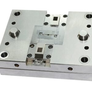


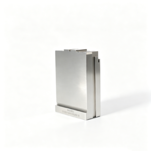


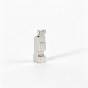
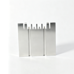
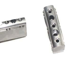
CNC Machined Clamp Blocks: Review Before Commitment
Drawing-driven categories for workholding, precision mold components, connector tooling, and custom-machined parts, planned around critical dimensions, materials, and inspection requirements.
DFM Before Quotation
Review geometry, material requirements, quantity, and machining access early to identify practical risks before production commitments are made.
Critical Dimensions Defined
Identify critical-to-quality features, tolerances, and surface requirements so the machining and inspection approach follows the drawing priorities.
Datum Strategy Aligned
Confirm functional datums and locating relationships to support repeatable setup planning, controlled measurement, and meaningful inspection results.
Process Route Planned
Select an appropriate sequence of CNC machining, EDM, grinding, and fitting based on feature access, allowances, and part requirements.
Inspection Planned Early
Match measurement methods and reporting expectations to critical features before production, helping ensure documentation reflects the agreed inspection plan.
Revisions Kept Visible
Wire EDM services and sinker EDM services address hardened materials, internal profiles, narrow slots, sharp geometry, and features inaccessible to conventional cutting tools. Electrode strategy, wire path, finish requirements, and recast-layer considerations should be agreed before production.
Clamp Blocks and Related Precision Components
Drawing-driven categories for workholding, mold, connector and custom-machined parts, planned around critical dimensions, materials and inspection requirements.

CNC Machining Services
Precision CNC machining services for custom clamp blocks, fixtures and related parts, with process planning based on the drawing, material, critical dimensions, machining access and required inspection evidence.
Upload a Drawing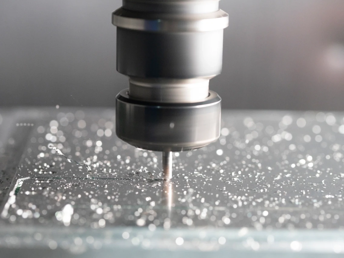
CNC Milling
Custom CNC milling services for clamp blocks, workholding plates and prismatic components. Drawing review considers datum faces, pocket access, threaded features, flatness requirements and practical machining sequence.
Upload a Drawing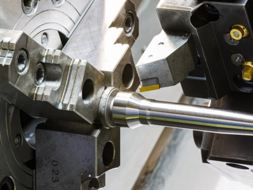
CNC Turning
Precision CNC turning services for cylindrical locating elements, shafts, bushings and threaded components. Requirements should define functional diameters, concentricity, surface condition, material and any post-machining treatment.
Upload a Drawing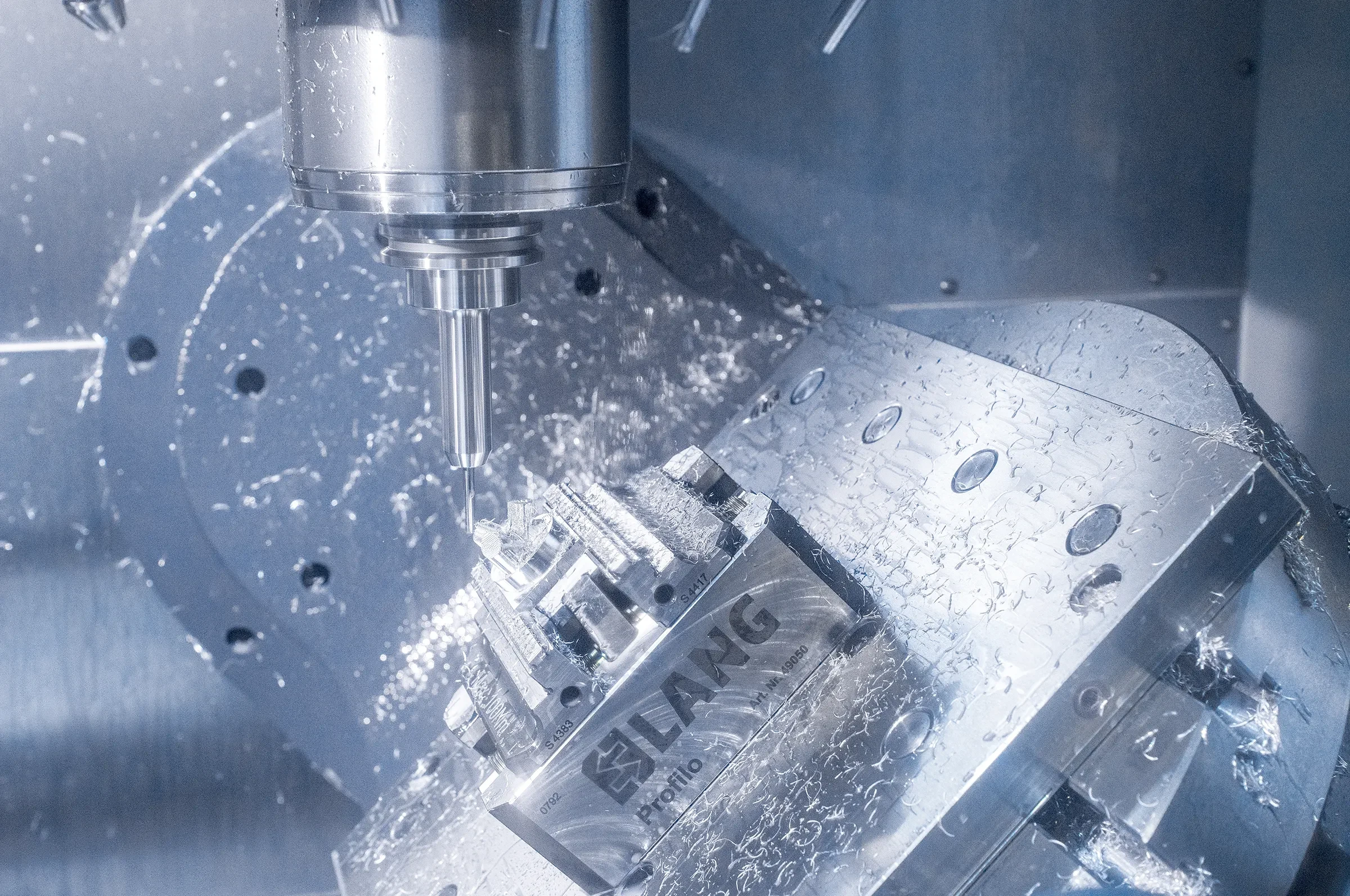
5-Axis Machining
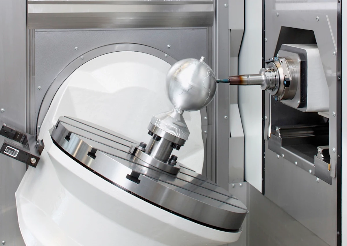
5-axis CNC machining supports complex clamp-block geometry, angled features and multi-face work where tool access and setup reduction affect the process route. Feasibility depends on geometry, tolerance priorities and inspection strategy.
Upload a Drawing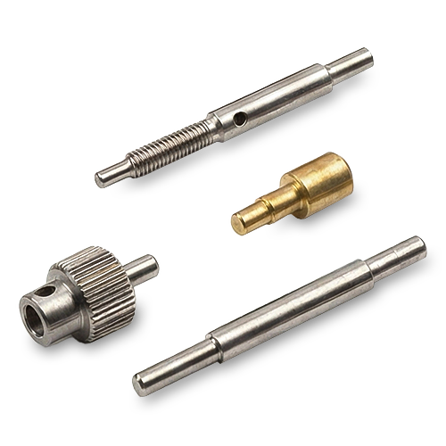
Swiss & Micro Machining
Swiss machining and micro machining support small, slender or detail-intensive components such as pins, sleeves and precision connector elements. Review focuses on feature scale, material behavior, critical diameters and measurement method.
Upload a Drawing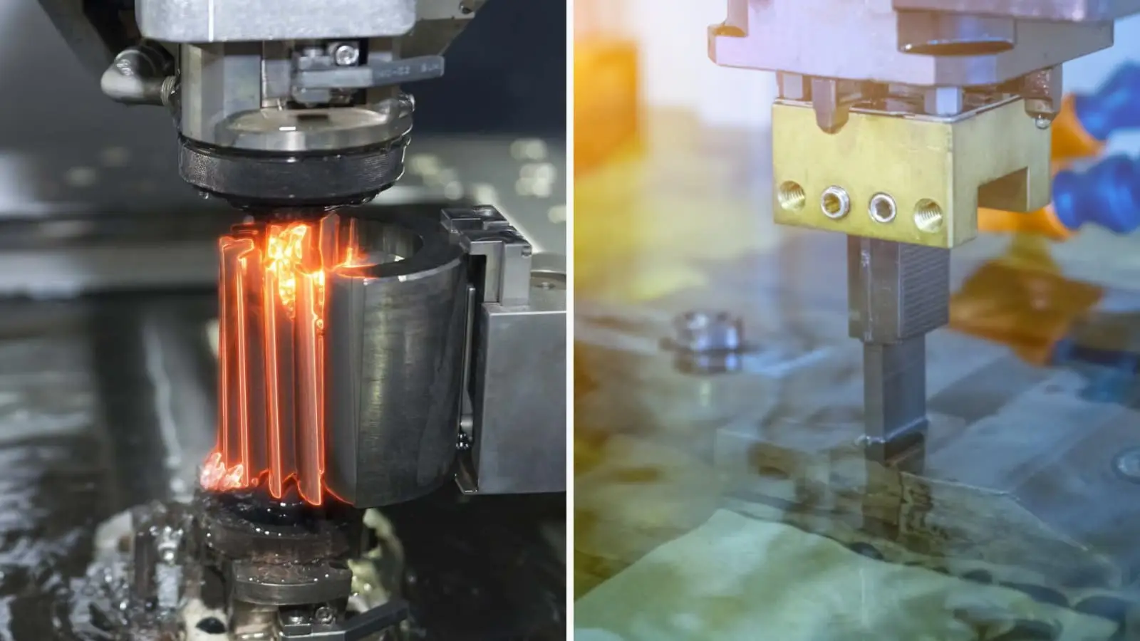
Wire & Sinker EDM
Wire EDM and sinker EDM services address hardened materials, internal profiles, narrow slots, sharp geometry and features inaccessible to conventional cutting tools. Electrode strategy, wire path, finish requirements and recast-layer considerations should be agreed before production.
Upload a Drawing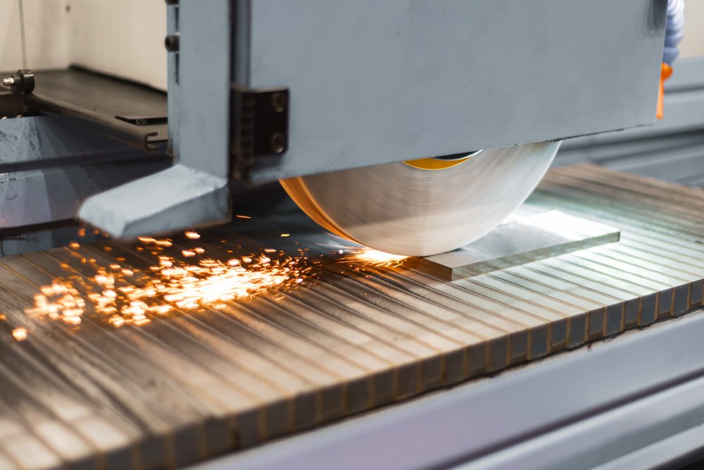
Precision Grinding
Precision surface and profile grinding provides controlled flatness, parallelism, profile accuracy and surface condition for clamp faces, wear components and mold details. Grinding stock, heat-treatment sequence and datum requirements guide planning.
Upload a Drawing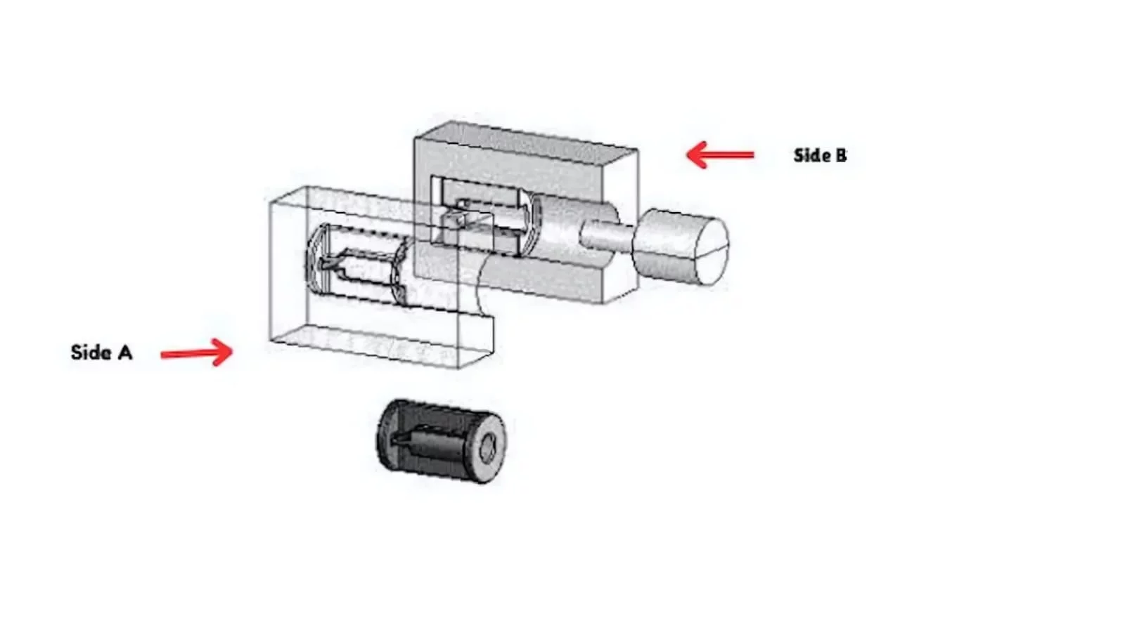
Mold Core & Cavity Inserts
Precision mold core and cavity inserts are produced from approved drawings and material requirements, with machining, EDM, grinding and fitting planned around shutoff surfaces, cavity detail, cooling interfaces and critical dimensions.
Upload a Drawing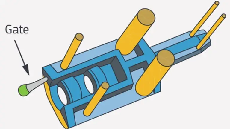
Ejector & Ejection Components
Ejector pins, sleeves and ejection components are evaluated for fit, running clearance, hardness requirements, surface condition and mating relationships. The drawing should identify functional diameters and any inspection or traceability needs.
Upload a Drawing
Core Pins, Guide & Locating Components
Core pins, guide pins and locating components support repeatable positioning and controlled mold movement. Review should clarify datum relationships, fit class, material, heat treatment, wear surfaces and mating-part context.
Upload a Drawing
Slides, Lifters, Gates & Mold Accessories
Mold slides, lifters, gates and accessories are configurable component families for moving, guiding and feeding functions. Process planning considers travel interfaces, shutoff geometry, wear areas, assembly fit and inspection priorities.
Upload a Drawing
Connector Mold Components
Precision connector mold components are made for drawing-defined connector tooling features, including fine-pitch, alignment and mating interfaces. Feasibility review addresses feature scale, material, EDM needs, surface requirements and dimensional control.
Upload a Drawing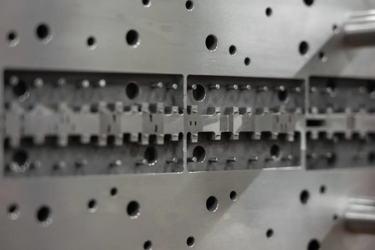
Stamping Die Components
Precision stamping die components include drawing-based punches, dies, guide elements, wear components and custom inserts. Material condition, heat treatment, grinding allowance, working edges and fit with mating components require clear specification.
Upload a Drawing
Injection, MIM, CIM & Overmolding Tooling
Injection, MIM, CIM and overmolding tooling components are assessed within verified production scope. A productive RFQ identifies molding application, resin or feedstock context, insert geometry, surface requirements, tooling interfaces and quality expectations.
Upload a Drawing
Machining Materials
CNC machining materials are selected against the drawing and functional requirement, including machinability, strength, corrosion resistance, wear behavior and heat-treatment compatibility. Specify the required grade, condition and material documentation needs.
Upload a Drawing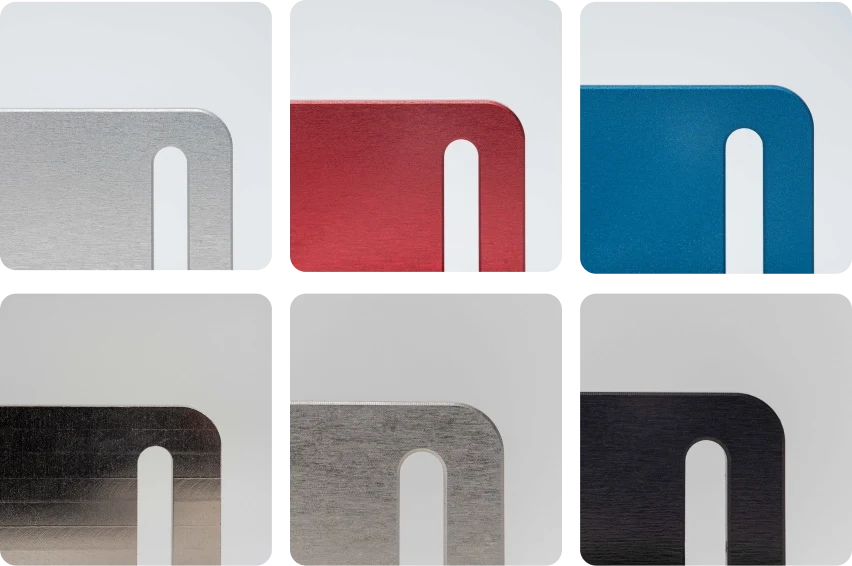
Surface Finishes & Heat Treatment
Surface finishing and heat treatment are planned as controlled steps, not assumed defaults. Define the required finish, coating or thermal treatment, functional surfaces, masking needs, dimensional impact and verification requirements.
Upload a Drawing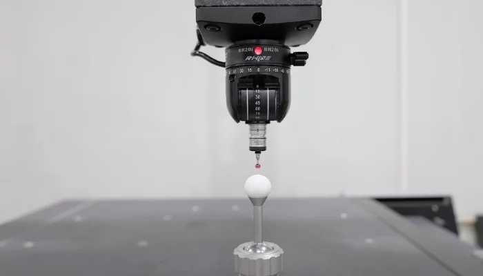
Quality, Metrology & Documentation
Precision inspection, metrology and quality documentation are aligned to the order and inspection plan. Identify critical dimensions, datums, reporting format, sampling expectations, revision status and any material or treatment records required.
Upload a Drawing
Prototyping & Low-Volume Production
Rapid prototyping and low-volume manufacturing support drawing-based development, qualification and limited production needs. Include quantity, target date, revision maturity, material, critical features and inspection requirements so the process route can be evaluated responsibly.
Upload a DrawingMaterials for CNC Machined Clamp Blocks
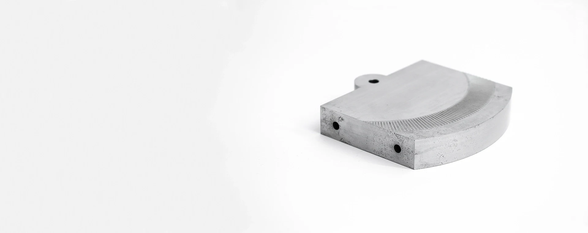
Tool Steels
Tool steels suit clamp blocks exposed to repeated contact, localized loading, or wear. Grade, heat-treatment sequence, grinding allowance, and critical datums should be defined from the drawing and application review.
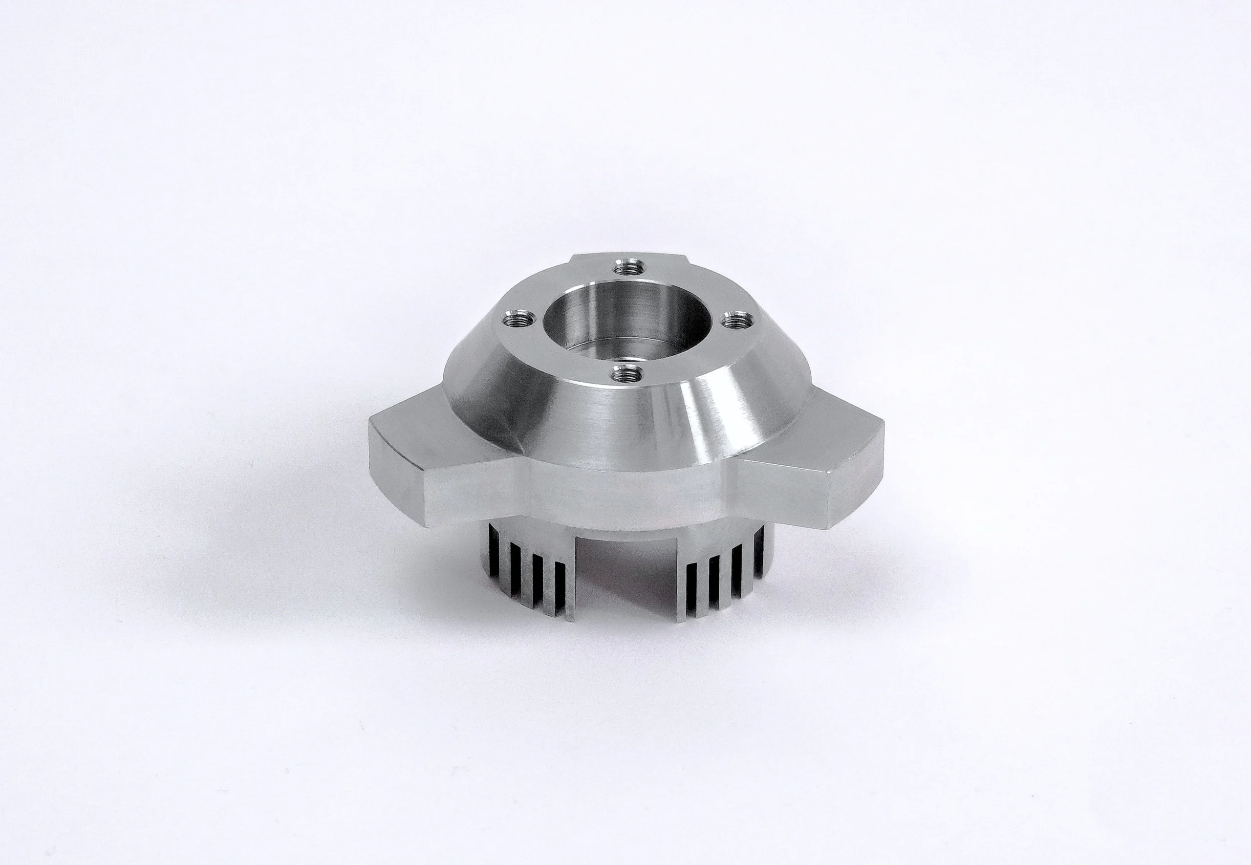
Stainless Steels
Stainless steels are considered where corrosion resistance or clean operating environments matter. Review the specified grade, hardness condition, thread requirements, surface finish, and any mating-material concerns before selecting the process route.
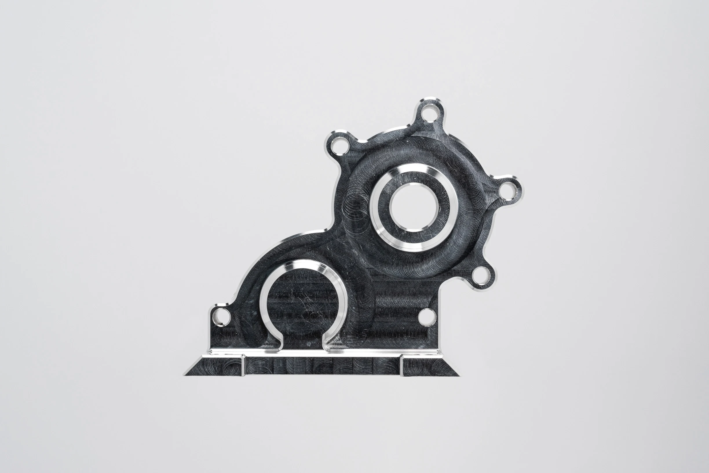
Aluminum Alloys
Aluminum alloys can reduce fixture weight for handling-oriented or lower-load applications. Alloy, temper, wall thickness, thread engagement, contact protection, and stiffness requirements should be assessed against the clamp-block geometry.
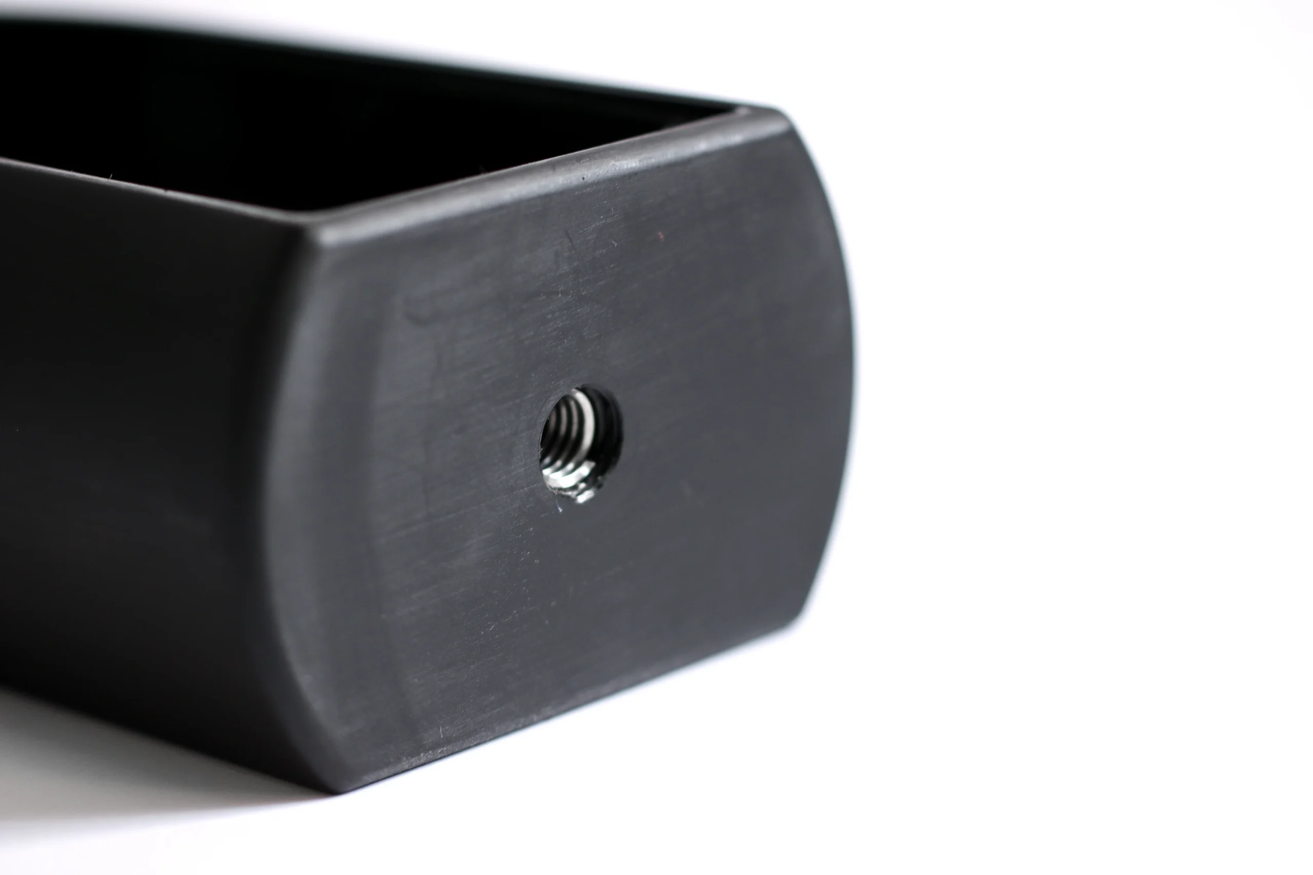
Engineering Plastics
Engineering plastics may fit non-marring contacts, electrical isolation, or low-load fixture interfaces. Material choice depends on temperature, chemical exposure, creep risk, machining stability, and the required dimensional inspection method.

Specified Materials
Customer-specified materials can be evaluated from the drawing, material designation, certification needs, quantity, and performance context. SUUXIANG confirms machinability, sourcing evidence, process sequence, and inspection expectations before quotation.
Precision Processes for CNC Machined Clamp Blocks
CNC Milling
CNC milling forms faces, pockets, slots, bores, and locating features on clamp blocks. Tool access, datum setup, and clamping loads are reviewed to support stable machining and controlled feature relationships.
CNC Turning
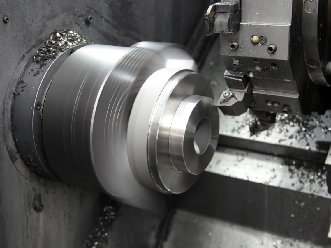
CNC turning produces concentric diameters, shoulders, threads, and rotational clamp features where the drawing calls for them. The process route considers runout requirements, material condition, and subsequent finishing operations.
Wire EDM
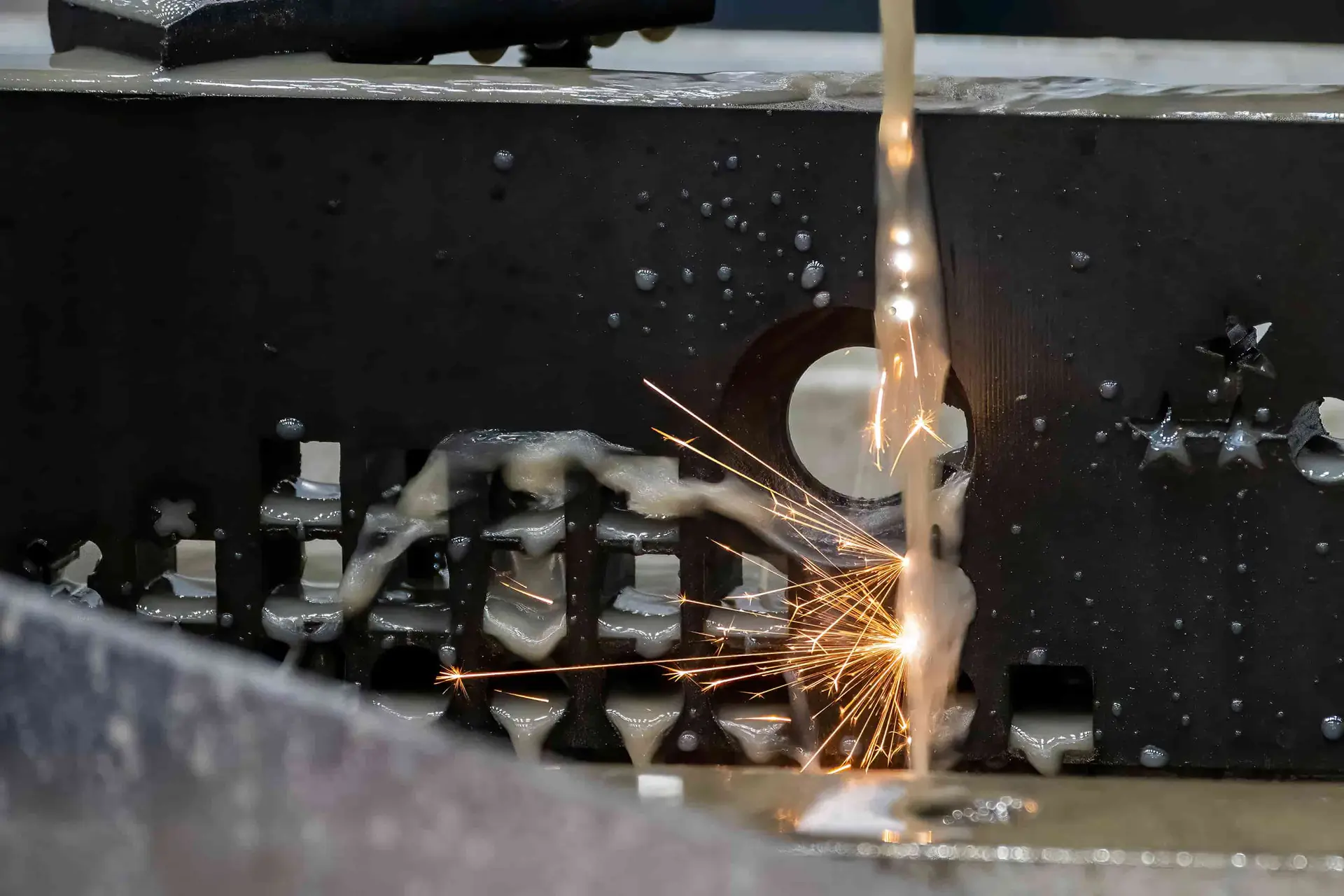
Wire EDM cuts precise profiles, narrow slots, and hardened-material features without conventional cutting forces. Wire path, start holes, corner conditions, and finish requirements are evaluated against the functional geometry of the part.
Sinker EDM
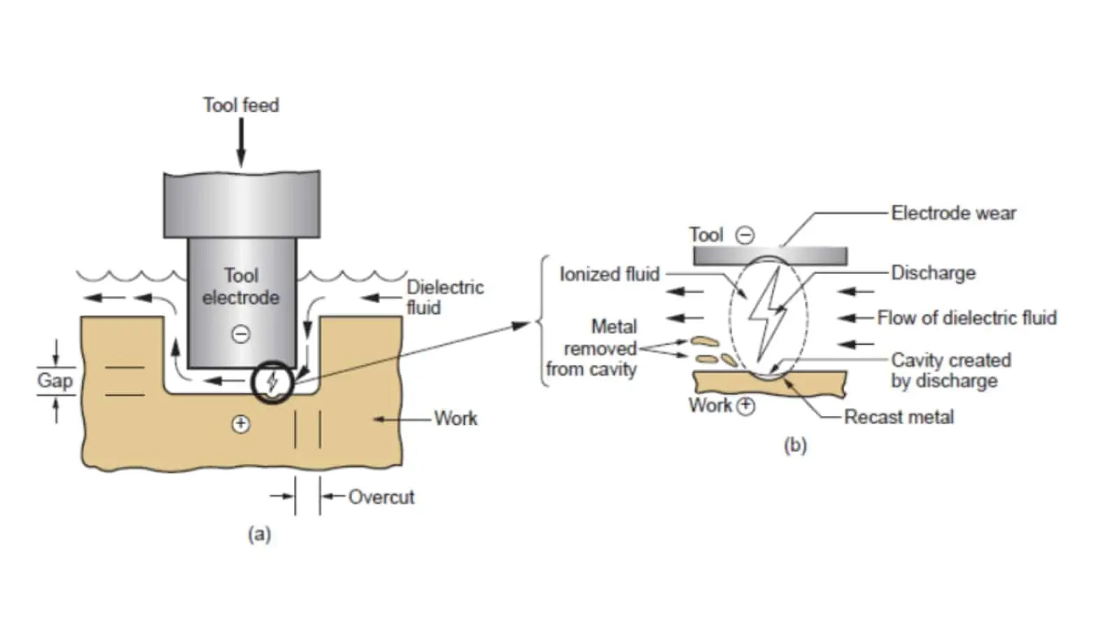
Sinker EDM creates internal details, sharp-cornered cavities, and complex forms where milling access is limited. Electrode design, spark allowance, surface requirement, and downstream polishing or fitting needs guide the planned approach.

Precision Grinding
Precision grinding refines critical faces, diameters, and parallel or perpendicular relationships after suitable stock allowance is retained. The route considers heat-treatment sequence, datum control, surface needs, and the specified inspection method.
CNC Machined Clamp Blocks: Hardware and Accessories
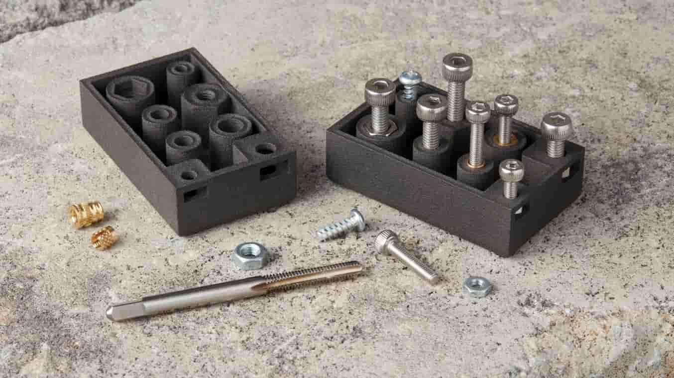
Threaded Features
Tapped holes, threaded bores, and customer-defined thread forms can be incorporated for fixture mounting, adjustment, or mating assemblies, subject to drawing review of engagement, tool access, material, and inspection requirements.

Locating Pins
Pin holes and locating-pin interfaces help establish repeatable part position in fixture assemblies. Define datum relationship, fit requirement, insertion direction, and whether the pin is supplied, installed, or accommodated by the clamp block.

Dowel Interfaces
Reamed or precision-machined dowel locations can support repeatable alignment between clamp blocks, base plates, and mating tooling. Share the dowel diameter, fit callout, datum scheme, and assembly sequence with the RFQ.

Mounting Fasteners
Clearance holes, counterbores, countersinks, and captive-fastener provisions can be designed around the specified mounting hardware. Confirm head style, access direction, tightening clearance, and any load-path considerations before machining begins.

Wear Bushings
Replaceable bushing seats or guided interfaces may be accommodated where repeated motion or locating contact requires serviceable wear components. Provide bushing data, retention method, concentricity needs, and mating-pin information for review.
Mating Hardware
Customer-specified screws, pins, inserts, sensors, or other mating hardware can be considered within the clamp-block design. Supply component drawings or models so interface dimensions, assembly clearances, and inspection points remain traceable.
About SUUXIANG Precision Manufacturing
SUUXIANG is the public-facing brand of Dongguan SuuXiang Precision Mold Co., Ltd., established in 2010 in Chang’an Town, Dongguan, Guangdong, China. We help international engineering and sourcing teams turn drawings, models and specifications into inspected custom parts through a disciplined, project-specific manufacturing workflow.
Our practical scope combines CNC milling and turning, multi-axis machining, EDM, precision grinding, fitting and inspection for custom CNC parts, mold components, connector tooling and die components. For CNC machined clamp blocks, the production route is defined by the drawing, material, critical dimensions, workholding needs and inspection requirements.
What distinguishes SUUXIANG is an engineering-led review before production commitments. We discuss datum strategy, tolerance stack, tool access, machining allowance, EDM or grinding needs, revision control and reporting expectations so the quoted process reflects the actual part requirement.

How SUUXIANG Builds CNC Machined Clamp Blocks
DFM and Datum Review
SUUXIANG reviews the drawing, 3D model, locating faces and critical dimensions before CNC machined clamp blocks move toward quotation. The discussion identifies datum relationships, tool access, clamping loads, thread engagement and features that may require a revised machining sequence.
- Confirm functional datums and mating interfaces
- Flag thin walls, deep pockets and restricted tool access
- Align material, heat treatment and surface requirements
- Record revision status before process planning

CNC and EDM Route Selection
Process planning matches each feature to practical access and finish requirements. CNC milling or turning may establish the main geometry, while wire EDM or sinker EDM can be evaluated for narrow slots, internal profiles, sharp transitions or features not suited to conventional cutting access.
- Separate machined geometry from EDM-dependent features
- Review electrode strategy for inaccessible internal details
- Consider wire path, start-hole and relief requirements
- Coordinate sequence around material condition and distortion risk
Grinding and Fitting Strategy
For clamp blocks with controlled contact faces or locating relationships, grinding allowance and fitting needs are reviewed as part of the route. This helps protect functional surfaces after heat treatment and keeps final adjustments tied to the drawing’s datum and tolerance strategy.
- Define surfaces that require grinding stock
- Plan heat-treatment sequence before final sizing
- Review contact faces and assembly-clearance needs
- Keep fitting work within documented functional requirements
Inspection and Revision Control
Inspection planning is coordinated with the order’s critical features, measurement method and reporting needs. SUUXIANG keeps drawing revisions, dimensional priorities and delivery information visible through the project so final documentation corresponds to the agreed inspection plan for the supplied clamp blocks.
- Identify critical-to-quality dimensions before production
- Match inspection methods to feature geometry
- Confirm requested reports and traceability expectations
- Maintain clear revision and delivery communication
Why Engineering Teams Choose SUUXIANG for CNC Machined Clamp Blocks
For cnc machined clamp blocks, compare drawing-led review and documented production planning with a typical quote-only sourcing path.
← Swipe left or right to view →
CNC Machined Clamp Blocks: From Drawing to Delivery
A drawing-led sequence keeps critical dimensions, process decisions, inspection requirements, and revision status visible before shipment coordination.
RFQ and Drawing Review
Share 2D drawings, models, material, quantity, delivery target, and quality requirements. SUUXIANG identifies critical dimensions, datums, tool access, and manufacturability questions.
DFM and Process Planning
The team aligns machining sequence, workholding approach, EDM or grinding needs, heat-treatment timing, machining allowance, and inspection method before production commitments.
Material and Setup Control
Material requirements and revision details are confirmed against the order. Setup planning considers locating surfaces, clamping force, accessible features, and protection of functional faces.
Machining and Secondary Processes
CNC milling, turning, multi-axis machining, EDM, grinding, and fitting are applied as the approved route requires, with process decisions matched to drawing priorities.
Inspection and Documentation
Finished parts are checked against the agreed inspection plan, focusing on critical dimensions, surface requirements, and order-specific reporting or traceability documentation.
Packing and Shipment Coordination
After inspection release, parts are protected for transit and delivery details are coordinated. Any required records are prepared to match the confirmed order and inspection scope.
Start Your CNC Machined Clamp Blocks RFQ
Provide the drawing package and critical requirements so SUUXIANG can review the manufacturing route before production commitments are made.
Submit Your Drawing Package
Send the 2D drawing, 3D model when available, quantity, application context, and target delivery date for initial engineering and sourcing review.
Confirm Critical Requirements
Identify material, heat treatment, datums, critical dimensions, surface requirements, mating interfaces, and any inspection or reporting expectations before quotation.
Review DFM and Quotation
Evaluate the proposed machining, EDM, grinding, and inspection route, with questions on tool access, tolerances, revision status, pricing, and sampling addressed.
Approve Production Release
Confirm the agreed drawing revision, requirements, and commercial details; production proceeds through the approved process plan with visible coordination and inspection documentation.
CNC Machined Clamp Blocks: Certification and Quality Documentation Review
CNC Machined Clamp Blocks: Verified Customer Outcomes
Approved customer testimonial or documented project case pending verification. Published outcomes will identify the application, drawing revision, inspection evidence, and measurable result supported by the project record.
Approved customer testimonial or documented project case pending verification. Published outcomes will identify the application, drawing revision, inspection evidence, and measurable result supported by the project record.
Approved customer testimonial or documented project case pending verification. Published outcomes will identify the application, drawing revision, inspection evidence, and measurable result supported by the project record.
Customer Evidence Publication Policy
Practical RFQ, quality, delivery and project-control questions for drawing-based clamp block sourcing.
What is the MOQ for cnc machined clamp blocks?
Can you review my drawing for cnc machined clamp blocks before quoting?
How long do cnc machined clamp blocks take to sample and produce?
Which materials and heat treatments can be specified for clamp blocks?
Can I request an inspection report with my order?
Do you ship custom clamp blocks internationally?
What payment information is needed before placing an order?
How does SUUXIANG handle drawings and intellectual property?
Complete Buyer’s Guide to cnc machined clamp blocks
A practical decision framework for specifying clamp blocks, evaluating drawing-based CNC suppliers, controlling fit and repeatability risks, and avoiding costly material, tolerance, inspection, and lead-time mistakes.
1. What Are cnc machined clamp blocks?
1. A clamp block is a drawing-defined workholding or positioning component that applies force, establishes a stop, supports a load path, or creates a controlled interface between a part and tooling. CNC machined clamp blocks are typically specified by their mounting pattern, contact geometry, datum relationship, and clearance envelope—not by a generic block size.
2. In a fixture, the block may restrain a workpiece while a separate screw, strap, cam, or hydraulic element supplies force. In molds, connector tooling, and stamping dies, it can locate or retain a component, back up a sliding element, or provide a repeatable mounting interface; prototype and low-volume setups often use the same logic with application-specific geometry.
3. A complete clamp assembly includes the force-generating mechanism and all mating hardware, whereas a clamp block may be only one precision-made member. A generic machined block becomes a clamp block only when its drawing-defined faces, holes, pockets, grooves, or reliefs serve a specified securing, locating, supporting, or interfacing function.
2. Evolution of Precision Clamp-Block Workholding
1-off manual setups commonly relied on adjustable straps, step blocks, and operator judgment. They remain useful for prototypes, but repositioning can change contact points, clamping load, and datum repeatability between runs.
3-axis CNC milling made application-specific clamp blocks practical when a fixture needed repeatable bore locations, support faces, slots, and reliefs. As mold, stamping-die, and connector tooling adopted tighter interfaces and faster changeovers, buyers increasingly needed controlled datums, compatible mounting patterns, and identifiable revision status rather than a generic block.
2D drawings and 3D models now need a DFM-led review before machining. Specify the part datum scheme, mating geometry, clamp-force direction, tool and wire access, material and heat-treatment sequence, critical dimensions, surface requirements, inspection method, and revision; these inputs determine whether the block can locate, clamp, and release without distortion or interference.
3. Types of cnc machined clamp blocks
Six clamp-block architectures cover flat, round, adjustable, and irregular workpieces. Select from the contact geometry, cutting-force direction, required adjustment, and cutter access—not block appearance.
| Type | Geometry And Purpose | Typical Application | Design Limitation |
|---|---|---|---|
| Stepped support | Tiered face supports strap clamp | Flat prismatic work | Height reduces stiffness |
| V-groove or radius | Curved seat locates round stock | Shafts and tubes | Surface marking risk |
| Locating or stop | Datum face arrests movement | Repeat production | May block loading |
| Slotted adjustable | Slot permits position adjustment | Variable-size setups | Lower repeatability |
| Split or post clamp | Bore or post applies retention | Bushed features | Can distort thin walls |
| Contoured fixture | Profiled contact supports shape | Irregular parts | Low reuse |
Support And Locating Blocks
Stepped support blocks set strap-clamp height under flat work; their limitation is reduced rigidity at tall settings.
Locating and stop blocks establish repeatable datum faces for prismatic parts; they must not obstruct loading or tool paths.
Round And Adjustable Work
V-groove or radius blocks cradle shafts or cylindrical features; select a contact form that resists side load without marking the surface.
Slotted adjustable blocks shift position over a defined range; slot clearance can reduce repeatability under reversing loads.
Dedicated Retention Forms
Split or post-clamp blocks apply localized force around a bore or post; thin walls can distort when clamp load rises.
Contoured fixture blocks match irregular casting or molded profiles; dedicated contact geometry limits reuse but improves support and access.
4. Materials for cnc machined clamp blocks
Material choice sets clamp-block stiffness, contact behavior, corrosion risk and handling mass. For cnc machined clamp blocks, evaluate the workpiece contact before selecting the stock grade.
| Material | Stiffness/Wear | Corrosion/Mass | Typical Control |
|---|---|---|---|
| Aluminum alloy | Moderate; low wear | Good with anodize; light | Hard anodize; steel inserts |
| Carbon/alloy steel | High; good wear | Needs protection; heavy | Black oxide or plating |
| Stainless steel | Moderate-high; galling risk | High resistance; heavy | Passivation; isolate sliding |
| Tool steel | High; excellent after hardening | Low resistance; heavy | Heat treat and grind |
| Engineering plastic | Low; non-marring | Good; very light | Replaceable contact pad |
Material Tradeoffs
6061 aluminum suits lighter fixtures and easy machining; hard anodizing improves surface protection. Carbon or alloy steel carries higher clamping loads, while tool steel is preferred where repeated sliding wear justifies heat treatment.
Environment And Contact
304 or 316 stainless is useful where corrosion resistance and cleanliness matter, but it can gall at sliding interfaces. Engineering plastics such as POM or UHMW-PE reduce marring on finished parts, yet need generous sections because stiffness and wear resistance are lower.
Specify The Decision
For prototypes or frequent revisions, select readily machinable aluminum or steel and document the contact pad separately. For production, state clamping load, cycle count, coolant exposure, cleanliness needs, heat treatment, coating, and permitted marking on the drawing.
5. Custom Features and Surface Treatments
Features on cnc machined clamp blocks should be specified from the locating and clamping scheme, not added after machining. Identify every functional face, mating fastener, datum, and contact condition on the drawing.
| Treatment | Primary Purpose | Dimension Or Inspection Concern |
|---|---|---|
| Anodizing | Aluminum corrosion protection | Specify masked fits and thickness control |
| Black oxide | Steel appearance and light protection | Oil film affects friction and gauging |
| Nickel plating | Wear or corrosion protection | Buildup can tighten bores and threads |
| Passivation | Stainless surface cleaning | Confirm material and post-process inspection |
Functional Machining Features
Threaded holes, counterbores, slots, bores, dowel locations, and reliefs each require a stated datum and tolerance. A dowel bore and its mating fastener clearance should not be controlled from unrelated outside faces.
Radiused contact faces can spread load and reduce marking, while protective contact pads can isolate sensitive workpieces. Define pad material, retention method, replaceability, and whether its thickness establishes clamp height.
- Call out thread class and usable depth
- Dimension counterbores from the assembly datum
- Specify relief purpose and minimum clearance
Identification And Finishing
Engraved identifiers are cosmetic or traceability features unless the drawing assigns a functional requirement; keep them away from sealing, locating, and contact faces. State character size, depth, position, and revision marking rule.
Anodizing, black oxide, nickel plating, and passivation serve different corrosion, friction, or material-compatibility purposes. Coating buildup and post-treatment cleaning can alter bore fit, thread engagement, surface contact, and inspection access, so define masked surfaces and the inspection stage.
6. Construction Details That Determine Quality
A reliable clamp block is defined by relationships, not by nominal outside dimensions alone. The drawing should establish how the block locates, carries load, and is inspected before a machining route is agreed.
Datums And Geometric Control
Datum A should be the functional seating face; establish B and C from the mating location. Specify parallelism, perpendicularity, and bore position relative to these datums so tolerance stack-up is inspectable.
Critical bores need a stated bore-to-face relationship, not only a diameter tolerance. Identify the inspection method when a CMM, pin gauge, or surface plate is required.
Load Path And Contact
Contact pads should distribute clamping force over stable, intentional areas. Small or uneven contact zones can mark a softer mating part, tilt the block, or locally distort thin sections.
Stiffness depends on section thickness, unsupported span, and force direction. State maximum permitted deflection or functional seating criteria where clamp load affects alignment.
Threads, Access, And Edges
Threaded holes require thread size, class, depth, usable engagement, and bottom condition on the drawing. Confirm tool access for drills, taps, cutters, and any required deburring operation.
Edge breaks need a defined size or an explicit burr-free requirement. Call out protected contact faces, cosmetic surfaces, and acceptance criteria for raised burrs around bores and threads.
- Datum references and controlled geometric relationships
- Bore location relative to functional faces
- Thread engagement and bottoming condition
- Permitted edge break, burr, and marking criteria
7. How to Select a Clamp-Block Manufacturer
Two supplier records matter before award: the drawing-review response and the proposed inspection plan. For risk-sensitive cnc machined clamp blocks, evaluate evidence tied to the released revision, not broad capability statements.
| Evaluation Area | Evidence To Request | Warning Sign |
|---|---|---|
| DFM | Marked drawing review | Generic acceptance |
| Quality | Inspection plan and report | Unspecified checking |
| Traceability | Revision and material records | Verbal confirmation |
| Launch | First-article process | No approval gate |
Review The Drawing Response
Two files—the 2D drawing and 3D model—should trigger questions on datums, tool access, clamping, EDM, grinding stock, and critical dimensions. A useful DFM response identifies risks and proposes controlled alternatives.
Verify Material And Inspection
One order should define material grade, heat-treatment condition, surface requirement, and report scope. Request material documentation when required, dimensional results against critical features, and a first-article or sample approval process.
Test Project Control
Each revision needs a visible revision identifier, acknowledgement, and disposition of affected work. Prototype-to-low-volume support should include packing protection, delivery updates, and one accountable technical contact.
8. Common cnc machined clamp blocks Buying Mistakes
Nine recurring handoff errors can turn an otherwise simple clamp-block order into rework, delayed assembly, or unusable workholding. Resolve them during drawing review, before a purchase order locks the revision.
Datums, Loads, And Mating Parts
First, nominal dimensions without datums leave inspectors and machinists referencing different faces; ask: which datum scheme controls the clamp face, bore, and mounting pattern?
Second, an omitted load path or mating-component model can cause distortion, interference, or inadequate support; ask: where do clamping and reaction forces travel, and what interfaces must fit?
Material And Finish Assumptions
Third, selecting material by unit price alone can sacrifice stiffness, wear resistance, corrosion behavior, or heat-treatment compatibility; ask: what service load, environment, hardness, and treatment sequence govern selection?
Fourth, unplanned coating thickness can close bores, alter threads, and disrupt fits; ask: which surfaces receive coating, masking, or post-finish sizing?
Threads, Tolerances, And Inspection
Fifth, unclear thread callouts create wrong pitch, class, depth, or engagement; ask: what standard, size, tolerance class, depth, and blind-hole allowance apply?
Sixth, blanket tight tolerances raise cost and may conflict with coating or assembly needs; ask: which dimensions are truly critical-to-quality, and what inspection method verifies each?
DFM Before Approval
Seventh, approving a quotation without DFM review can hide inaccessible tools, weak sections, EDM needs, and grinding stock conflicts. Ask: has the supplier reviewed access, process sequence, datums, inspection plan, and revision-controlled deliverables?
9. From Drawing to Approved Production
A controlled launch converts prototype cnc machined clamp blocks into repeatable low-volume supply. SUUXIANG begins from the drawing, CAD model, application, quantity, and inspection expectations rather than a generic quotation.
Define Interfaces And Data
Step 1 assigns engineering ownership of function, mating faces, loading direction, datums, and allowable clamp travel. Procurement supplies target quantity and date; the supplier receives a dimensioned 2D drawing plus the current 3D model.
Close DFM And CTQs
Step 2 requests DFM feedback before release, covering tool access, thread engagement, corner radii, machining sequence, and inspectability. Engineering locks material and finish; quality identifies CTQs, datum references, measurement method, and acceptance criteria.
Approve Controlled Production
Step 3 reviews a sample or first article against the agreed inspection plan and records any deviation disposition. Procurement releases the controlled revision, while SUUXIANG maintains revision-visible production and repeat-order controls for drawing, material, finish, and reporting requirements.
10. cnc machined clamp blocks Pricing and Lead Time
1 drawing package—2D drawing, 3D model when available, material grade, quantity, datums, critical tolerances, finish, heat treatment, and inspection requirements—lets SUUXIANG quote a defined process route instead of a nominal block price. Stock size and material availability affect yield; machine time rises with deep pockets, difficult tool access, multi-axis geometry, tighter tolerances, EDM, grinding, and reporting.
3 quantity tiers illustrate the commercial effect: setup, programming, fixtures, and first-article inspection are concentrated in prototypes, then amortized across repeat parts. Heat treatment and surface finishing also add routing time, while consolidated releases can reduce repeated setup and shipment coordination.
2 apparent savings often increase project risk: omitting datum-based inspection or choosing undersized stock can create rework, distortion, or mating problems. Submit revision-controlled files, required certificates or reports, application context, and target delivery date so lead time and inspection scope can be evaluated against the order.
| Quantity tier | Indicative cost pattern | Lead-time effect |
|---|---|---|
| 1–5 pieces | Highest unit cost; setup dominates | Programming, material sourcing, and inspection drive schedule |
| 6–50 pieces | Setup spreads across parts | Repeat machining can improve flow after approval |
| 51+ pieces | Cost depends on routing and release plan | Consolidated orders may reduce repeated coordination |
Upload Your CNC Machined Clamp Blocks Drawing
Share quantity, material, critical dimensions, inspection needs, and target date so SUUXIANG can begin a disciplined DFM and quotation review.