
CNC Machined Mounting Brackets for Drawing-Driven OEM Builds
Submit your drawing for CNC machined mounting brackets, with DFM review, critical-dimension planning, and inspection aligned to project requirements.
Representative Precision Component Views





Related Components and RFQ Options


CNC Machined Mounting Brackets: Engineering Advantages
Plan critical bracket features around assembly function, machining realities, and documented inspection requirements before production begins.
Drawing Review First
Review drawings, models, materials, quantities, and functional requirements early to identify manufacturability questions before quotation and production planning.
Datum-Aware Planning
Define datum relationships for mounting faces, locating features, and hole patterns so critical dimensions support the intended assembly reference.
Machining Access Review
Assess tool access, clamping points, internal corners, and feature orientation to reduce avoidable machining constraints and setup risk.
Controlled Process Routing
Plan CNC machining, EDM, grinding, fitting, and surface-treatment sequence around geometry, machining allowance, and functional feature priorities.
Inspection Plan Alignment
Agree inspection methods and reporting needs for critical dimensions, threads, hole positions, and surfaces before parts move toward final inspection.
Revision Visibility
Keep drawing revisions, approved changes, and delivery information visible throughout coordination to help prevent outdated requirements reaching production.
Precision CNC Parts and Tooling Families
Explore configurable component and process categories built around drawing review, critical dimensions, process planning, inspection requirements, and revision-controlled delivery.

CNC Machining Services
Precision CNC machining services for drawing-based custom machined parts and precision mold components, with coordinated milling, turning, EDM, grinding, fitting, and inspection. Drawing review identifies critical dimensions, datum requirements, material conditions, surface priorities, and practical process routes before quotation or production commitment.
Upload a Drawing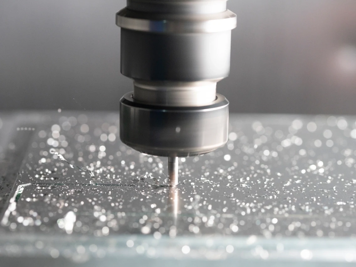
CNC Milling
Custom CNC milling services for prismatic parts, plates, housings, fixtures, and mold components. Machining access, tool reach, corner radii, wall geometry, datum setup, and finishing allowance are reviewed to support a workable milling strategy and inspection plan.
Upload a Drawing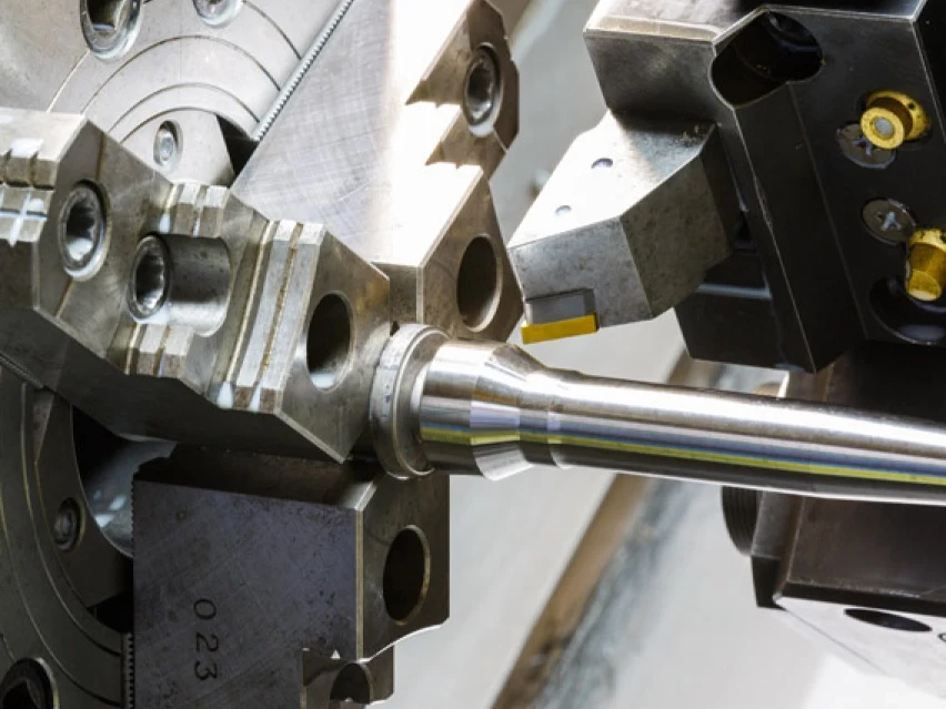
CNC Turning
Precision CNC turning services for shafts, sleeves, bushings, pins, threaded features, and rotational components. The process review considers concentricity, runout, datum selection, feature transitions, material condition, and secondary machining or grinding needs.
Upload a Drawing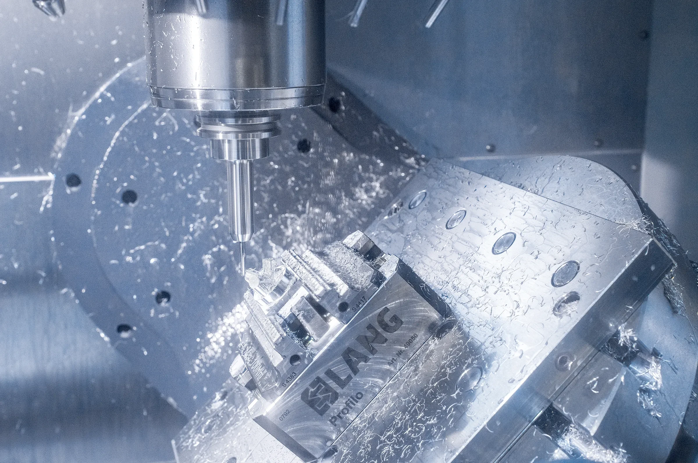
5-Axis Machining
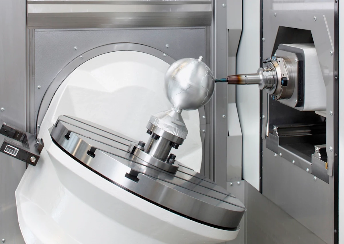
5-axis CNC machining supports complex part geometry where multiple faces, angled features, or tool-access constraints affect setup strategy. SUUXIANG evaluates orientations, tool clearance, clamping, surface transitions, critical dimensions, and whether multi-axis machining is appropriate for the drawing.
Upload a Drawing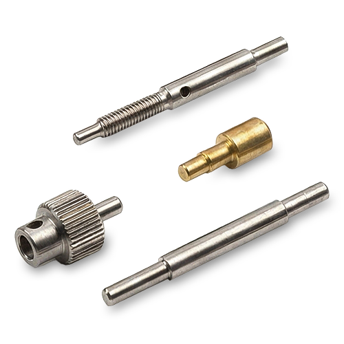
Swiss & Micro Machining
Swiss machining and micro machining support compact, detail-intensive turned components with small diameters, fine features, and demanding concentricity requirements. A drawing review addresses material form, feature accessibility, cutoff considerations, measurement method, and downstream finishing or heat-treatment sequence.
Upload a Drawing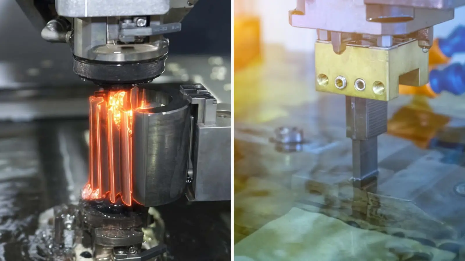
Wire & Sinker EDM
Wire EDM and sinker EDM services address hardened materials, narrow slots, internal profiles, sharp geometry, and features with limited conventional tool access. Process planning considers wire path or electrode strategy, flushing, corner conditions, recast-layer requirements, and inspection criteria.
Upload a Drawing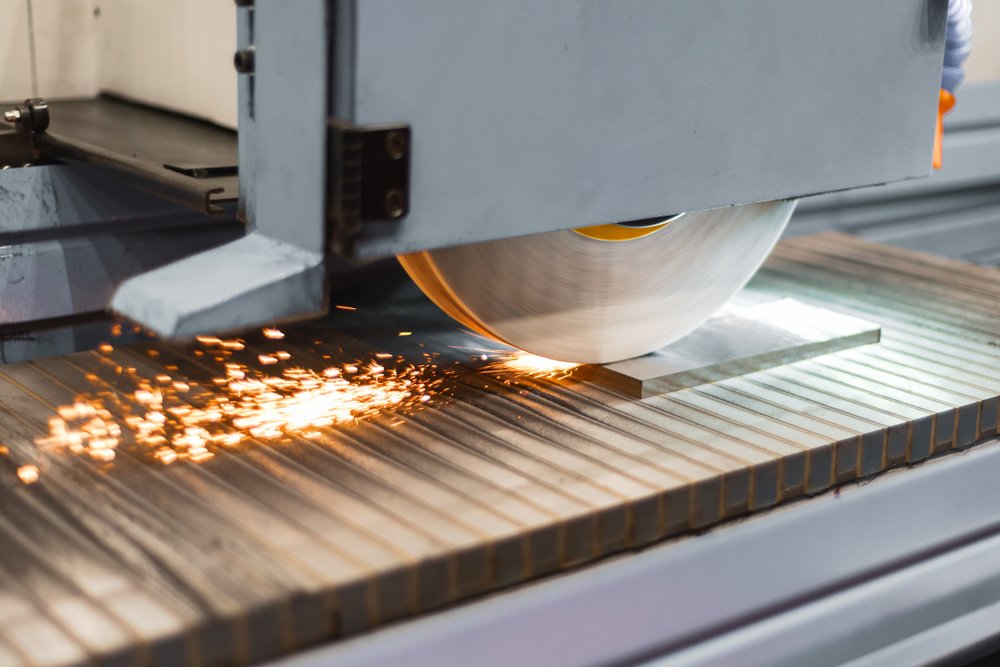
Precision Grinding
Precision surface and profile grinding supports flatness, parallelism, profile accuracy, and controlled finishing after machining or heat treatment. Grinding stock, datum condition, heat-treatment distortion risk, wheel access, surface requirements, and inspection method should be defined before release.
Upload a Drawing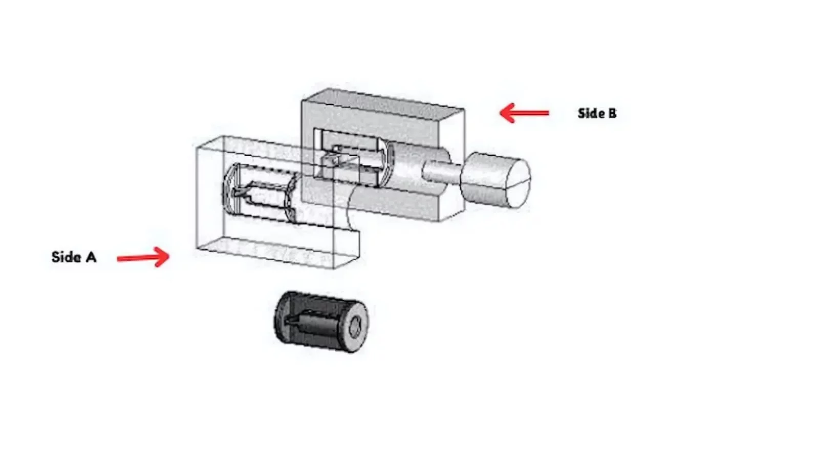
Mold Core & Cavity Inserts
Precision mold core and cavity inserts are produced from drawings and models with attention to shutoff geometry, cooling interfaces, EDM access, grinding allowances, material condition, and mating relationships. Critical dimensions and inspection requirements are reviewed as part of the planned process route.
Upload a Drawing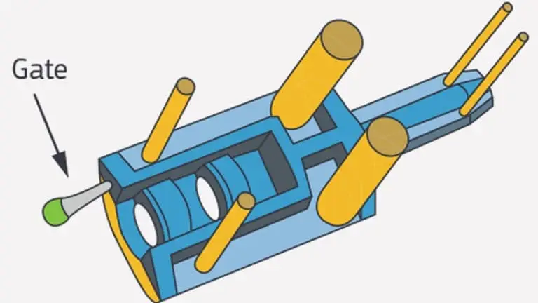
Ejector & Ejection Components
Ejector pins, sleeves, and ejection components require attention to fit, straightness, bearing surfaces, head geometry, surface condition, and heat-treatment sequence. SUUXIANG reviews functional interfaces and mating-part context to plan machining, grinding, and dimensional verification.
Upload a Drawing
Core Pins, Guide & Locating Components
Core pins, guide pins, and locating components are configured around functional datums, fit classes, alignment needs, wear surfaces, and mating features. Drawings should identify critical diameters, positional relationships, material and hardness requirements, and the required inspection evidence.
Upload a Drawing
Slides, Lifters, Gates & Mold Accessories
Mold slides, lifters, gates, and accessories are planned as functional tooling components rather than generic catalog items. Review focuses on travel and clearance interfaces, shutoff surfaces, guiding features, material treatment, machining access, fitting requirements, and controlled revision information.
Upload a Drawing
Connector Mold Components
Precision connector mold components support tooling features where pin pitch, cavity geometry, alignment, small details, and repeatable interfaces affect product performance. Process planning may combine CNC machining, EDM, grinding, and inspection based on the verified drawing requirements.
Upload a Drawing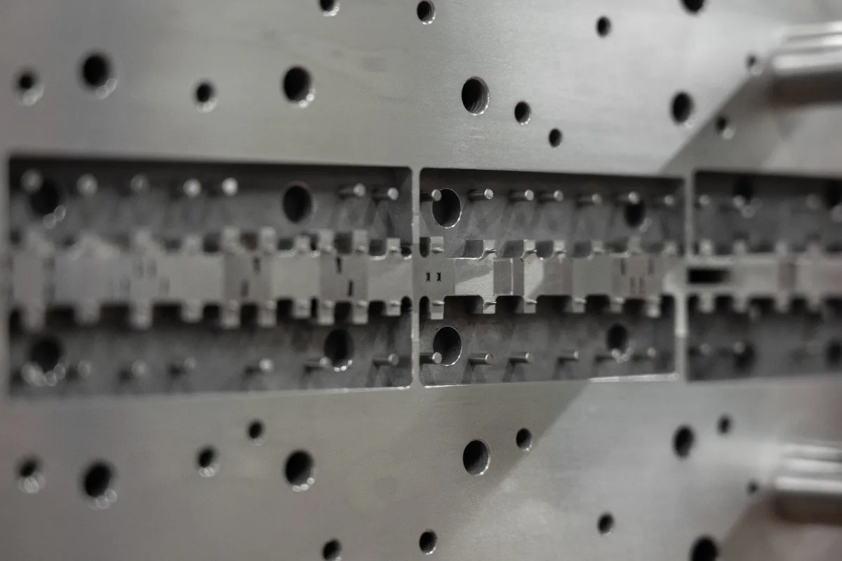
Stamping Die Components
Precision stamping die components are made for drawing-defined die sets, punches, inserts, guide elements, and wear parts. Material, hardness, cutting or forming edges, clearance relationships, grinding stock, and mating conditions are evaluated before the process route is confirmed.
Upload a Drawing
Injection, MIM, CIM & Overmolding Tooling
Injection mold components and tooling for injection molding, MIM, CIM, and overmolding are supported when requirements fit verified production scope. Drawing review considers parting and shutoff features, core and cavity details, gating interfaces, material condition, machining access, EDM needs, and inspection expectations.
Upload a Drawing
Machining Materials
CNC machining materials are selected against the drawing, application, machining behavior, heat-treatment requirement, corrosion considerations, and documentation needs. Buyers should specify the required grade or approved equivalent, material condition, and any traceability expectations with the RFQ.
Upload a Drawing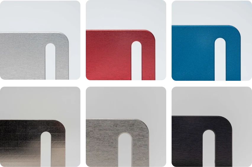
Surface Finishes & Heat Treatment
Surface finishing and heat treatment are planned as part of the dimensional process, not an afterthought. Requirements for roughness, coating, polishing, hardness, distortion control, masking, and final measurement should be identified so machining and finishing allowances can be managed.
Upload a Drawing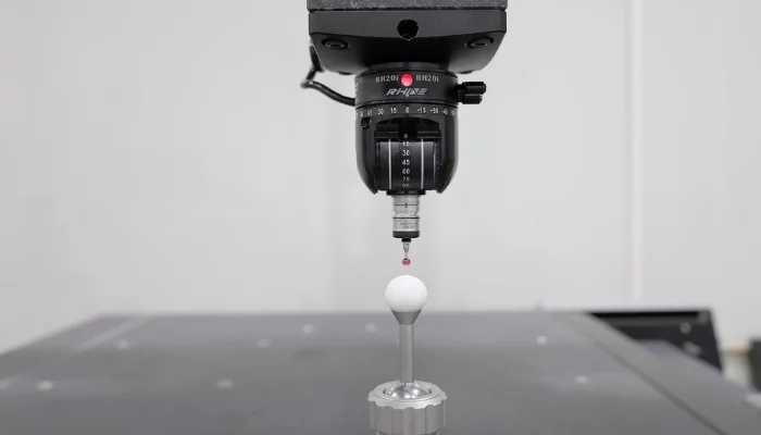
Quality, Metrology & Documentation
Precision inspection, metrology, and quality documentation are aligned with the order’s critical dimensions and agreed inspection plan. Requirements may include dimensional reports, material records, revision confirmation, surface verification, and traceable measurement evidence appropriate to the supplied specifications.
Upload a Drawing
Prototyping & Low-Volume Production
Rapid prototyping and low-volume manufacturing support drawing-based evaluation, tooling development, pilot needs, and controlled repeat orders. Submit the drawing, model where available, quantity, material, quality priorities, target date, and application context for a practical manufacturability review.
Upload a DrawingMaterials for CNC Machined Mounting Brackets
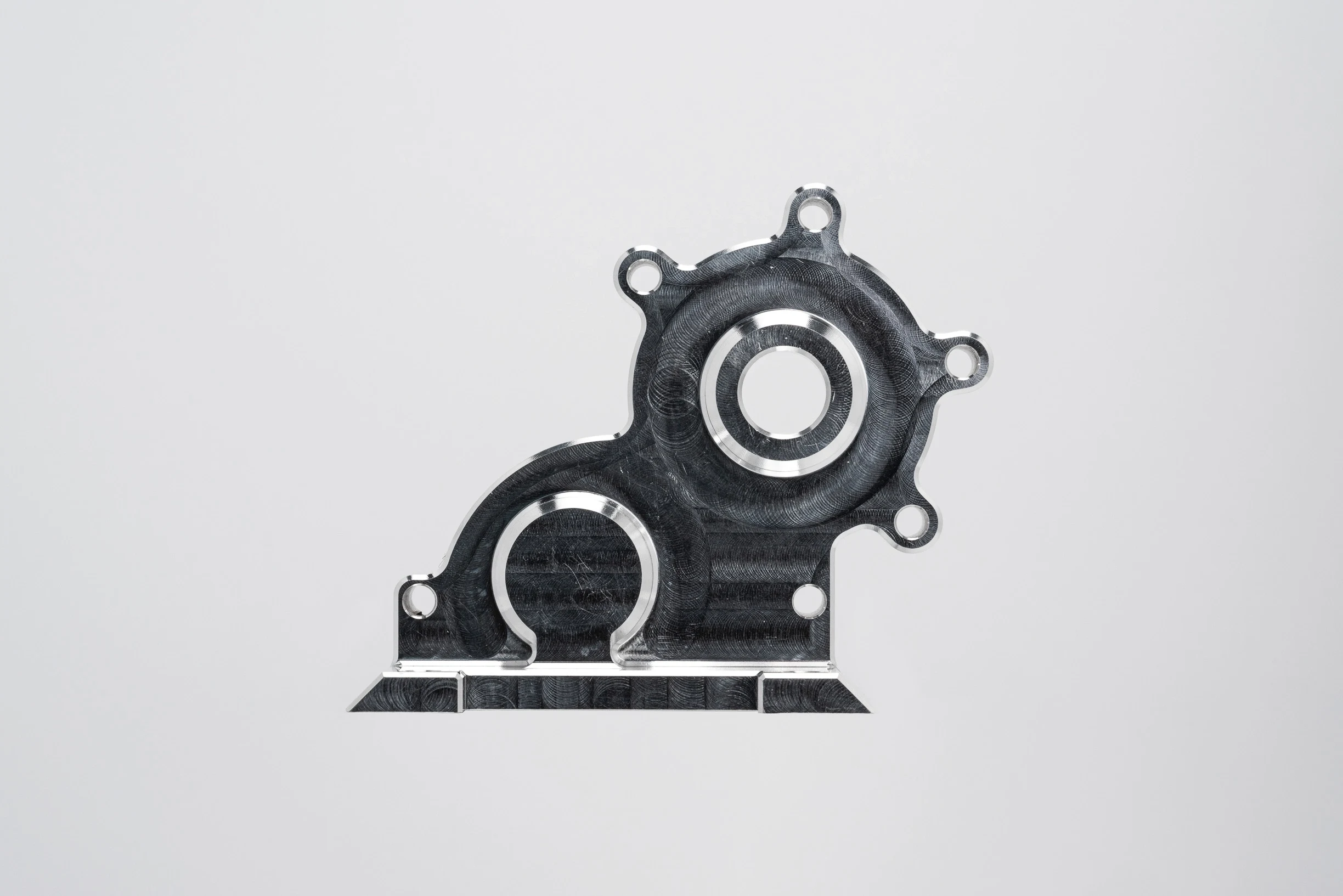
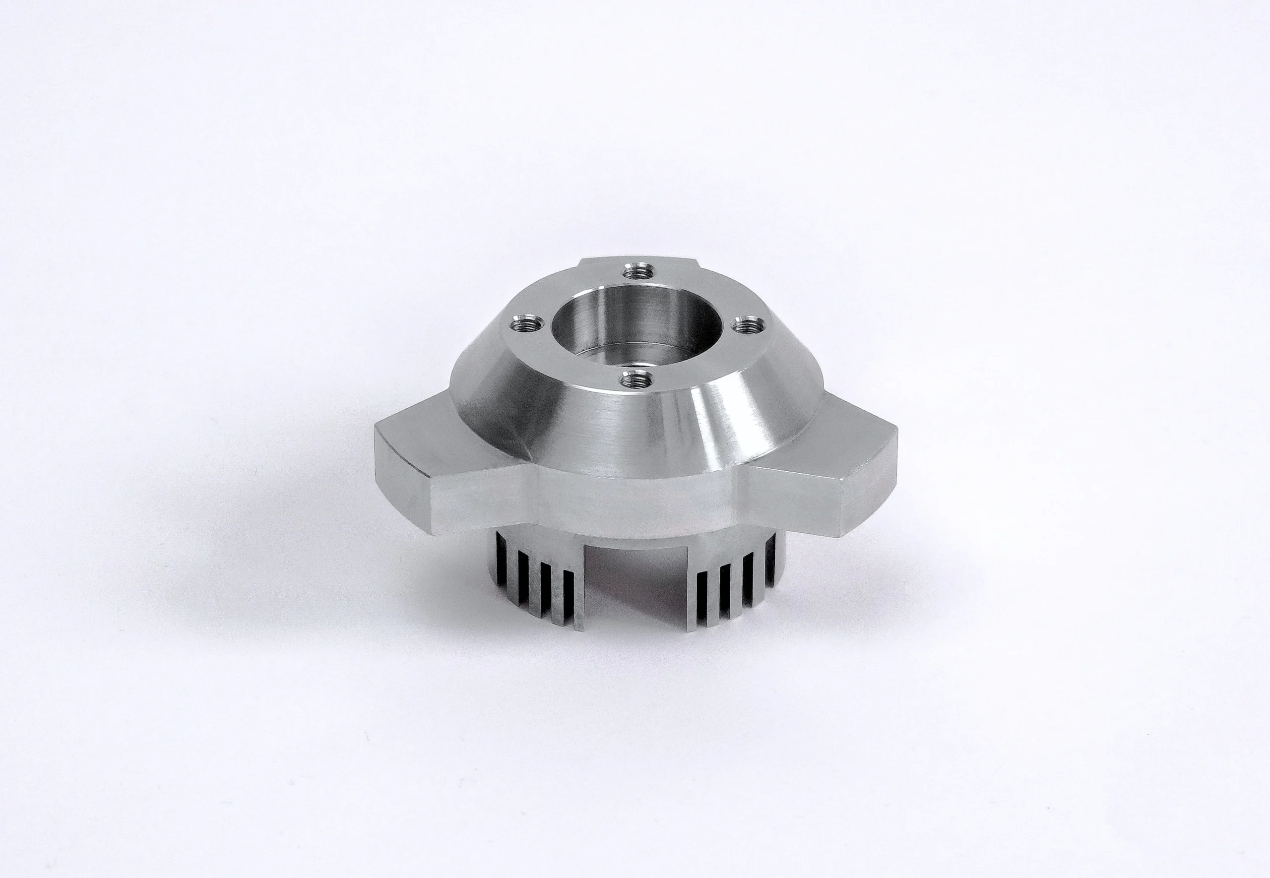
Aluminum Alloys
A practical choice for weight-sensitive mounting structures, aluminum offers favorable machinability and corrosion behavior when the specified alloy and finish suit the environment. Review wall stiffness, threaded-feature strength, and coating buildup on critical fits.
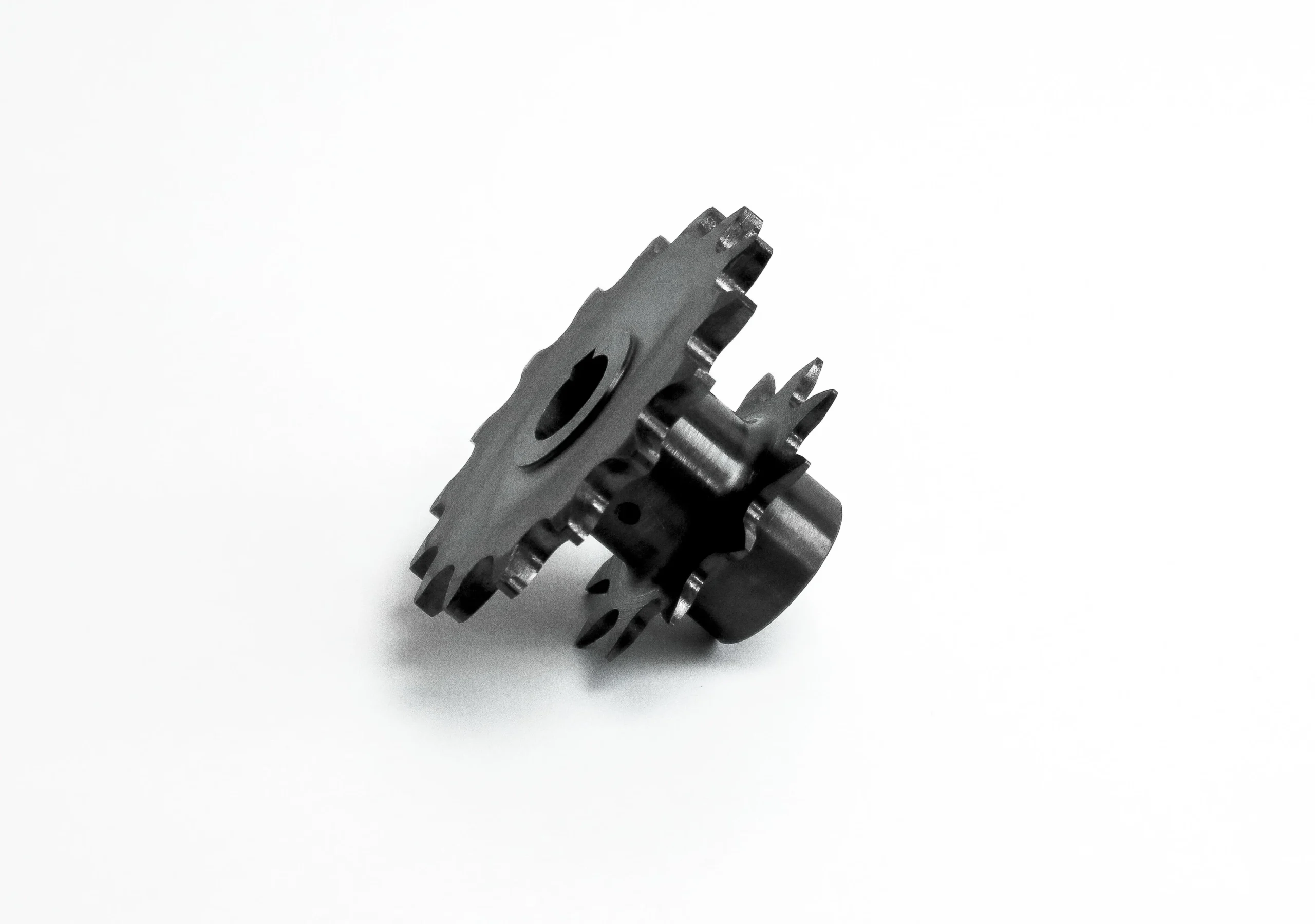
Stainless Steels
For brackets exposed to moisture, cleaning agents, or corrosive service conditions, stainless steel can provide durable corrosion resistance. Grade, condition, machining access, and any passivation requirement should be confirmed against load, finish, and inspection criteria.
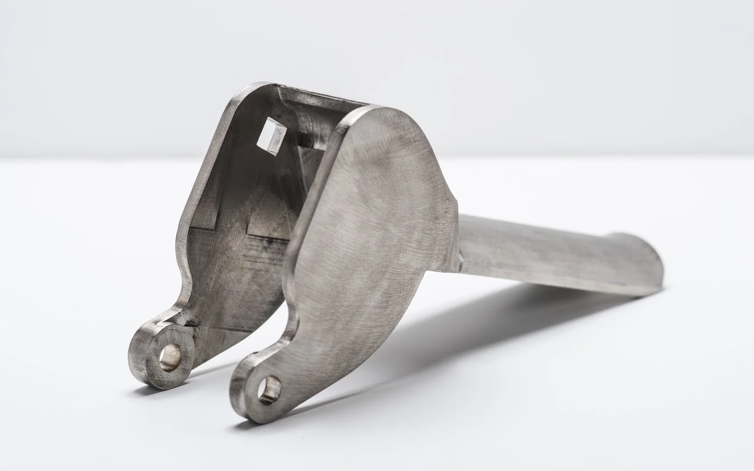
Carbon Steels
Carbon steel suits rigid equipment mounts and general structural interfaces where weight is less critical. Material condition, protective finish, weld-free geometry, and corrosion exposure affect the process route; flatness and hole-location requirements guide inspection planning.
Alloy Steels
Alloy steel may be considered for high-load brackets, locating features, or wear-sensitive interfaces. Heat treatment can change distortion risk and machining sequence, so hardness targets, grinding allowance, datum strategy, and post-treatment inspection requirements need early review.
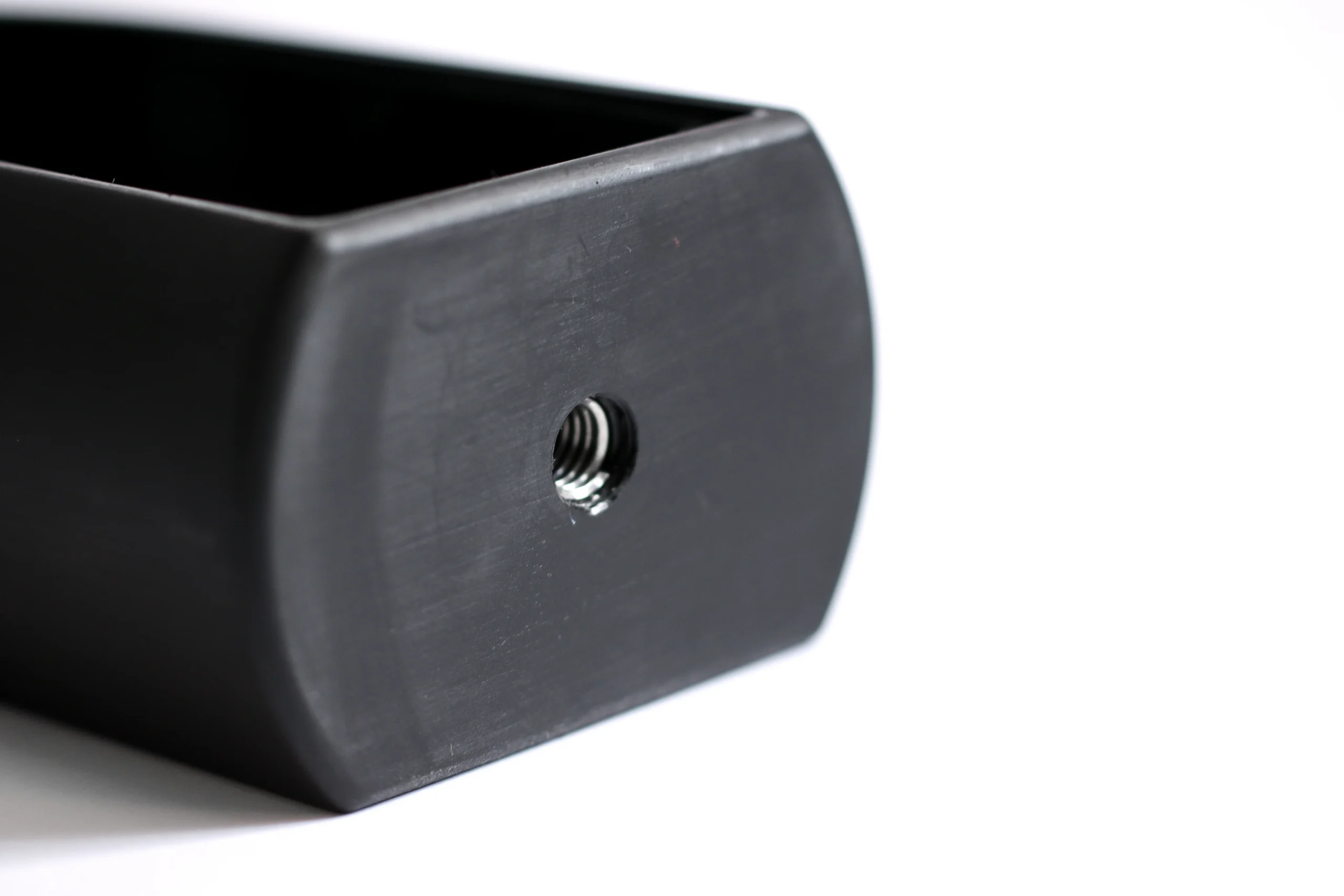
Engineering Plastics
Engineering plastics can serve lightweight, electrically isolating, or chemically resistant bracket applications when service loads permit. Grade selection should account for creep, thermal expansion, thread retention, machining support, and the dimensional references needed for assembly inspection.
CNC Machined Mounting Brackets: Supported Process Routes
CNC Milling and Turning
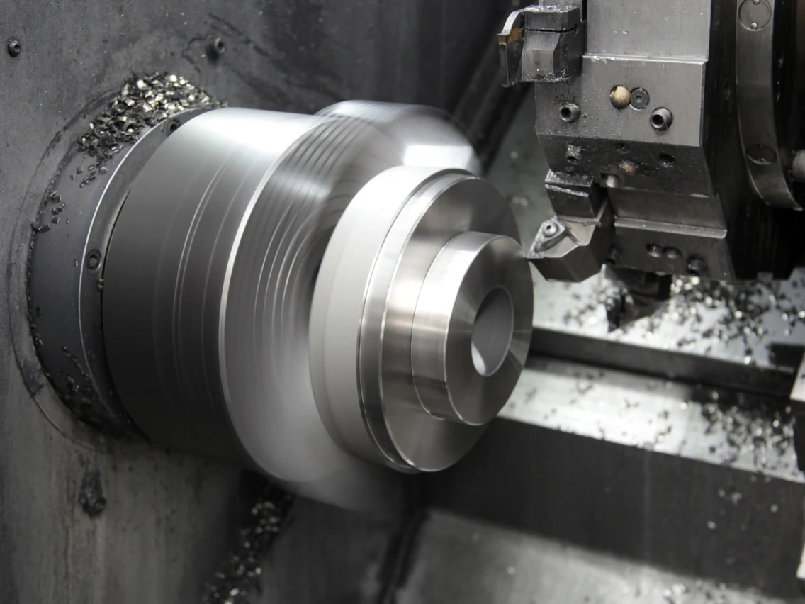
CNC milling forms mounting faces, pockets, slots, hole patterns, and profiles, while turning supports rotational features where the bracket design requires them. Fixture strategy is reviewed to protect datum relationships and accessible critical dimensions.
Wire EDM
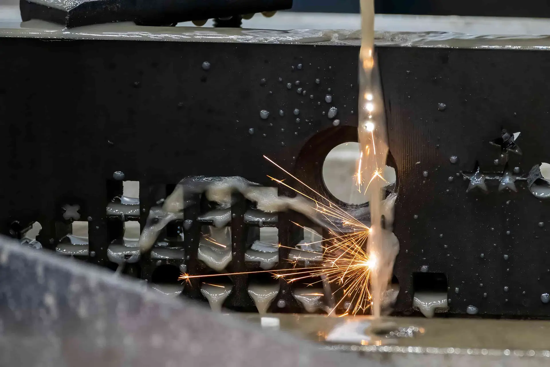
Wire EDM is considered for narrow slots, sharp internal profiles, hardened features, and geometry where conventional cutter access is limited. Wire path, start-hole location, finish allowance, and inspection points should be defined from the drawing.
Sinker EDM
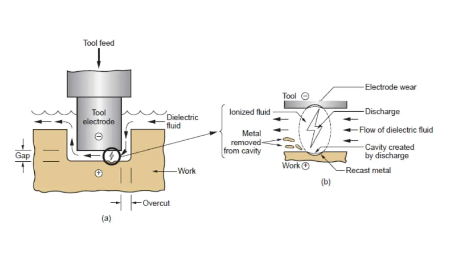
Sinker EDM supports internal forms, deep ribs, and difficult-to-machine details when electrode access and material condition justify the process. Electrode strategy, spark allowance, surface requirement, and subsequent finishing needs are reviewed before release.

Grinding and Fitting
Precision grinding refines selected faces, steps, and locating surfaces after the appropriate machining or heat-treatment sequence. Controlled fitting may be used where mating geometry requires verification, with grinding stock and functional contact areas identified in advance.
Inspection Planning
Inspection planning links critical dimensions, hole positions, threads, surface requirements, and datum references to suitable measurement methods. Reports and documentation are aligned with the order requirements, helping maintain traceability through revisions, production, and final delivery.
CNC Machined Mounting Brackets: Features and Hardware Options
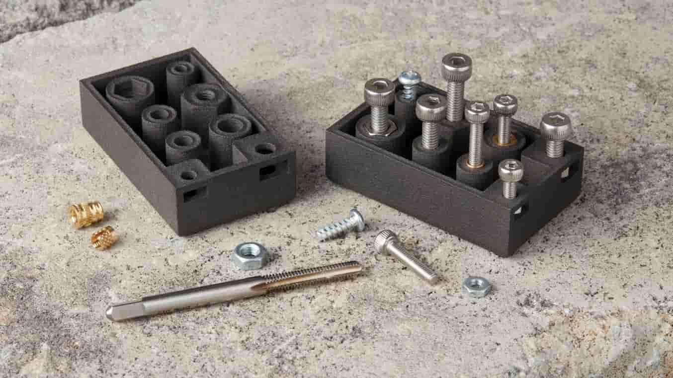
Threaded Holes
Tapped, threaded, countersunk or counterbored holes can be planned around fastener access, engagement requirements and finishing sequence. Identify thread standard, depth, class and any masking or post-finish machining needs on the drawing.
Thread Inserts
Helical, key-locking or other specified inserts can support repeated assembly in softer materials or repairable interfaces. Provide insert type, thread size, installation condition and pull-out or torque expectations for DFM review.

Locating Features
Dowel-pin holes, reamed bores, locating steps and datum faces help control repeatable bracket position against mating parts. Mark the functional datums, fit requirements and critical relationships that must be verified during inspection.

Assembly Fasteners
Fasteners, spacers, captive hardware and mating-component interfaces should be defined as drawing requirements rather than assumed catalog options. Share the assembly stack, access constraints and torque-sensitive features for a practical machining route.
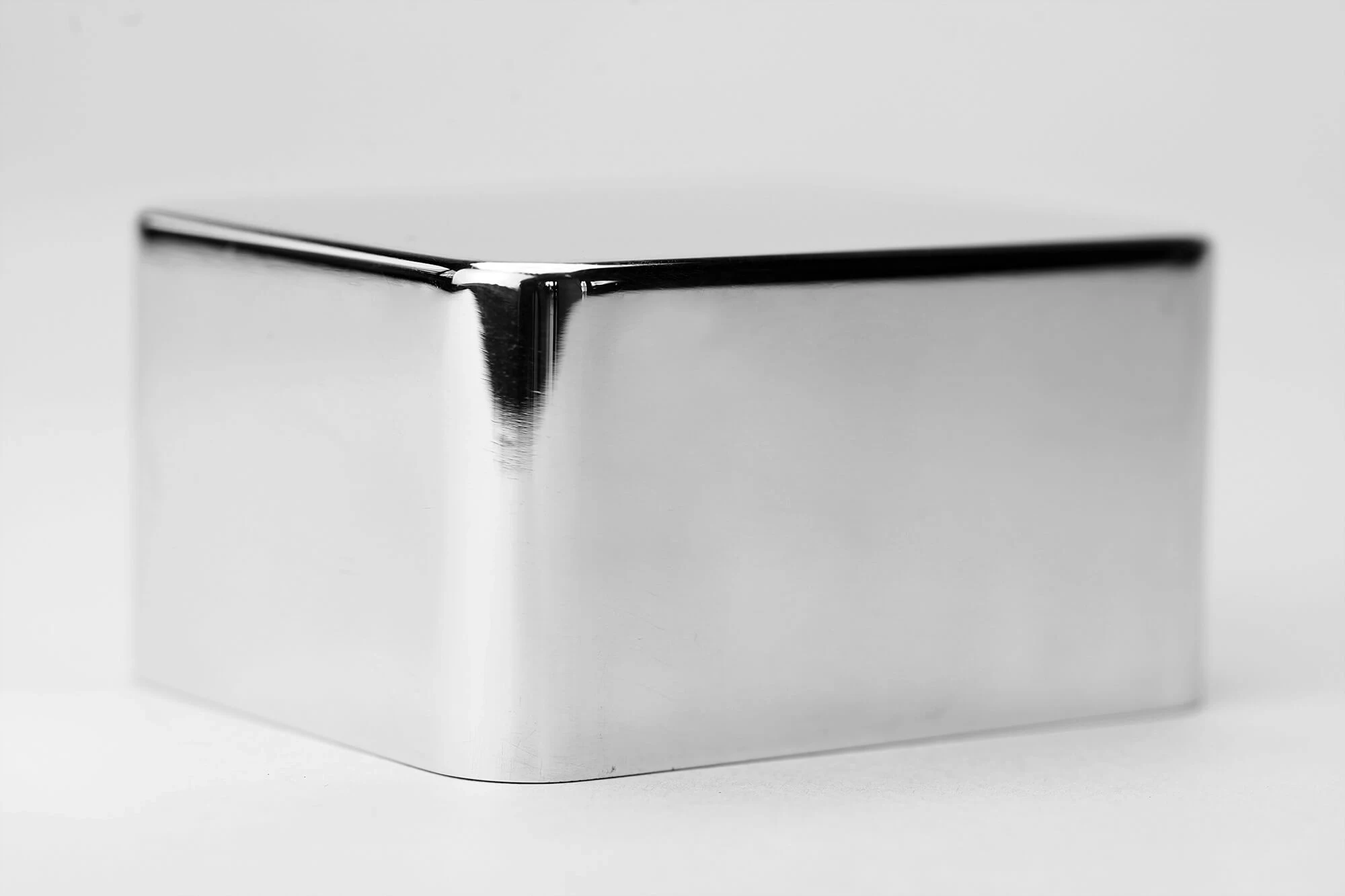
Surface Treatments
Anodizing, passivation, plating, bead blasting or other specified finishes may affect close fits, threads and sealing surfaces. State coating type, cosmetic zones, masking requirements and dimensional priorities before the process plan is finalized.
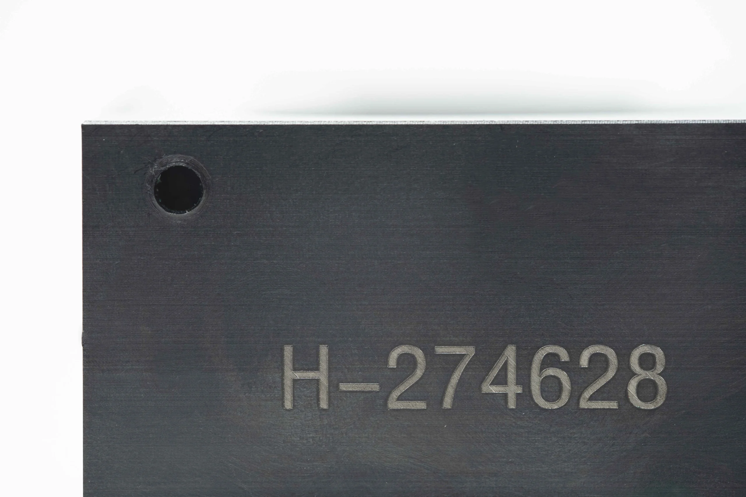
Identification Marks
Part numbers, revision marks, orientation indicators and traceability labels can be incorporated where the method suits the part and application. Define content, location, legibility expectations and whether marking must follow final finishing.
About SUUXIANG for CNC Machined Mounting Brackets
SUUXIANG is the sole public-facing brand of Dongguan SuuXiang Precision Mold Co., Ltd., established in 2010 in Chang’an Town, Dongguan, Guangdong, China. Founded by XiaoCheng Huang, the company helps global engineering and sourcing teams convert drawings and specifications into inspected custom parts, precision mold components, connector tooling, and CNC machined mounting brackets.
Our manufacturing scope combines CNC milling and turning, multi-axis machining, EDM, precision grinding, fitting, and inspection. For each project, the route is determined by the part’s geometry, material requirements, critical dimensions, datum strategy, access constraints, and required documentation rather than by a generic process template.
What differentiates SUUXIANG is disciplined project coordination before commitments are made. We review DFM, tolerance stacks, machining and grinding allowances, EDM requirements, inspection methods, and revision status with the drawing at the center. Submit your 2D drawing, 3D model, quantity, quality requirements, and target delivery date for a focused review.

CNC Machined Mounting Brackets: Assembly Fit Controls
DFM Before Commitments
SUUXIANG reviews the drawing, 3D model, datums, critical dimensions, material, and mating context before quotation or production commitments. This identifies tool access, clamping risks, tolerance-stack concerns, and design details that can affect the assembly fit of CNC machined mounting brackets.
- Confirm functional datums and critical-to-quality features
- Review hole patterns, threads, pockets, and mounting faces
- Identify clamping deformation and machining-access risks
- Align material, heat treatment, and surface requirements

EDM and Grinding Strategy
Where geometry or tolerance requirements justify secondary processes, SUUXIANG plans wire EDM, sinker EDM, and precision grinding around the drawing requirements. Electrode strategy, wire path, grinding stock, and heat-treatment sequence should be resolved before the process route is released.
- Assess EDM access for internal corners and fine features
- Plan grinding allowance around hardened or precision surfaces
- Sequence heat treatment to manage distortion risk
- Protect functional surfaces during finishing and fitting
Inspection Built Around Function
Inspection planning focuses on the dimensions that determine how the bracket locates, fastens, and interfaces with mating components. SUUXIANG aligns measurement methods and reporting expectations with the approved drawing, including critical hole positions, flatness, thread condition, and reference datums.
- Define inspection methods for critical dimensions
- Check datum-linked hole position and mounting geometry
- Confirm thread and locating-feature requirements
- Match final documentation to the verified inspection plan
Revision-Controlled Coordination
Drawing-based work depends on clear revision control from RFQ through delivery. SUUXIANG keeps material requirements, approved changes, quality expectations, and delivery information visible as the project progresses, helping procurement and engineering teams avoid building to superseded information.
- Record drawing and model revision status
- Clarify approved changes before production release
- Coordinate manufacturing and inspection requirements
- Provide order-aligned documentation at completion

Why Choose SUUXIANG for CNC Machined Mounting Brackets
A drawing-led workflow that keeps manufacturability, critical dimensions, inspection and revisions visible before production.
← Swipe left or right to view →
CNC Machined Mounting Brackets: From Drawing Review to Delivery
Each route is planned around the drawing, critical features, process access and agreed inspection requirements.
RFQ and Drawing Review
We review 2D drawings, 3D models, material, quantity, application context, target date, and inspection needs before defining a responsible quotation basis.
DFM and Process Planning
Critical dimensions, datums, tolerance stack, clamping strategy, tool access, surface requirements, and heat-treatment sequence are reviewed to establish the appropriate manufacturing route.
CNC Machining Execution
CNC milling, turning, multi-axis machining, or micro-machining are applied according to the approved process plan, preserving features that govern mounting and mating fit.
EDM and Grinding Control
Where geometry or finish requires it, wire EDM, sinker EDM, and precision grinding address inaccessible details, hardened features, controlled stock, and critical surfaces.
Inspection and Documentation
Inspection follows the agreed plan for critical dimensions, datum-related features, threads, surfaces, and other specified requirements, with order-matched records prepared when required.
Packing and Shipment Coordination
Accepted parts are packed for the component geometry and delivery route, while revision status, documentation requirements, and shipment coordination remain visible to the project team.
Start Your CNC Machined Mounting Brackets RFQ
A drawing-driven process for defining requirements, confirming scope, and coordinating inspected delivery.
Submit Your Drawing Package
Send the 2D drawing, 3D model when available, material, quantity, application context, target date, and inspection requirements for your CNC machined mounting brackets.
Confirm DFM and Quote Scope
Review critical dimensions, datums, tolerance stack, tool access, finishing, and inspection expectations with our team before quotation scope and process route are confirmed.
Approve Production Details
Approve the agreed revision, manufacturing details, quality plan, and sampling or production approach so controlled machining can begin against the documented requirements.
Follow Delivery Updates
Receive visible revision and delivery communication while CNC machining, EDM, grinding, fitting, and inspection progress according to the agreed project plan.
Certification and Quality Documentation
CNC Machined Mounting Brackets: Customer Project Outcomes
Customer testimonial pending approval. Publish a verified case only after the customer confirms the drawing revision, inspection evidence, delivery outcome, and permission to identify the project.
Customer testimonial pending approval. The final reference should document measurable results, such as first-article acceptance, critical-dimension inspection results, or delivery performance, against the applicable purchase order.
Customer testimonial pending approval. Before publication, confirm the customer’s approved wording, company attribution, and any numerical outcome so the case remains traceable to its controlled project documentation.
CNC Machined Mounting Brackets FAQ
Practical RFQ, engineering, quality, and delivery guidance for drawing-driven bracket projects.
Can you quote CNC machined mounting brackets from my drawing?
What is the minimum order quantity for cnc machined mounting brackets?
How long does it take to make cnc machined mounting brackets?
Which materials can be used for custom mounting brackets?
Can I request a first article or sample before a production order?
What inspection reports are available for bracket orders?
How do you protect drawings and project information?
What should I include in an RFQ for custom mounting brackets?
Complete Buyer’s Guide to cnc machined mounting brackets
Use a practical decision framework to specify bracket performance, compare materials and manufacturing routes, qualify suppliers, control cost, and avoid drawing, tolerance, finishing, and inspection mistakes before production.
1. What Are cnc machined mounting brackets?
A drawing-defined bracket is a precision-machined part that locates, supports, or secures one assembly to another through controlled mounting faces, holes, threads, or locating features. CNC machined mounting brackets transfer applied loads while preserving the intended position of sensors, housings, actuators, molds, or fixtures.
Two functional interfaces usually govern bracket performance: the machine-side datum and the mating-component datum. Their relationship affects alignment, vibration resistance, tool clearance, service access, and whether installation can be repeated without adjustment.
Machining choices distinguish a CNC bracket from a generic fabricated support: features can be machined from defined datums with specified flatness, positional tolerances, reamed or threaded holes, pockets, and controlled edge conditions. Before requesting a quote, provide the 2D drawing and 3D model, material and treatment requirements, quantity, critical dimensions and datums, surface requirements, mating context, inspection needs, revision level, and target delivery date.
2. Evolution of cnc machined mounting brackets
2D drawings once defined simple manually made supports mainly by overall size and hole location. As assemblies added repeatable mounting faces, threads, dowel locations, and angled interfaces, CAD-defined cnc machined mounting brackets made those relationships manufacturable from a shared geometry set.
3-axis, 4-axis, and multi-axis machining now allow complex hole patterns and features to be located from controlled datums rather than transferred by manual layout. That shift can reduce assembly variation only when the drawing identifies the functional interfaces, tolerances, and datum scheme—not merely nominal dimensions.
1 complete release package should pair the native or neutral 3D model with a revision-controlled 2D drawing, material specification, finish callouts, and an inspection plan for critical features. For prototype-to-production work, buyers should keep the same datums and acceptance criteria through each revision, then record any approved manufacturing change before repeating the part.
3. Types of cnc machined mounting brackets
Bracket geometry should follow the load path and assembly access, rather than visual familiarity. For cnc machined mounting brackets, identify the primary datum face, fastener approach, and mating-part orientation before routing machining.
Angle And Channel Forms
L-brackets carry corner loads across orthogonal faces; retain open screw access and specify leg thickness, inside radius, and datum faces.
U-brackets straddle a member with parallel mounting faces; communicate clearance, fastener direction, internal tool access, and whether a gusset redirects bending load.
Plate And Adjustable Forms
Base-plate brackets spread load into one broad face; provide hole pattern, flatness priority, counterbore access, and the supported component’s center of gravity.
Adjustable and panel brackets use slots or repeated patterns; define adjustment travel, clamp direction, slot-edge clearance, panel thickness, and tool approach.
Equipment-Specific Forms
Sensor brackets prioritize repeatable sensing-face orientation; state locating features, cable clearance, accessible fastening, and positional tolerances from the functional datum.
Motor, enclosure-mount, and multi-axis brackets manage torque or loads in several directions; submit the load vectors, mating faces, service-tool envelope, pocket depths, and angled-feature requirements.
4. Materials for cnc machined mounting brackets
6061 aluminum is often a practical starting point, but service loads and exposure—not familiarity—should set the material. Define the load path, temperature, fluids, electrical function, finish, and allowable mass before requesting a quote.
| Material | Primary Advantage | Key Limitation | Typical Decision Check |
|---|---|---|---|
| Aluminum alloys | Low mass; good machinability | Lower stiffness than steel | Weight and anodized finish |
| Stainless steels | Corrosion resistance | Higher machining effort | Exposure and load |
| Carbon/alloy steels | Strength and stiffness | Needs corrosion strategy | Rigidity and coating |
| Brass | Conductivity; machinability | Lower structural strength | Electrical contact |
| Titanium | High strength-to-weight | High cost | Mass-critical service |
| Engineering plastics | Electrical isolation | Creep risk | Load and temperature |
Compare Material Families
Aluminum, steel, brass, titanium, and engineering plastics solve different constraints. Compare stiffness, corrosion behavior, conductivity, finish route, and machining time against the installed environment.
Match Service Conditions
304 stainless suits many wet or corrosive locations, while carbon or alloy steel can favor rigid, heavily loaded brackets when protected. Titanium reduces mass but usually raises material and machining cost.
POM, nylon, or similar engineering plastics can provide electrical isolation and low mass, but require creep, temperature, and fastening-load review.
Control Interfaces And Finishes
6061 and 7075 differ in strength and corrosion trade-offs; confirm the required alloy rather than specifying aluminum generically. Anodizing suits aluminum, passivation supports suitable stainless grades, and plated steel requires coating coverage at threads and contact faces.
5. Customization and finishing options
One bracket drawing can combine fastening, location, clearance, and traceability features. For cnc machined mounting brackets, define each feature from its functional datum and identify surfaces that must remain untreated.
| Finish | Primary Purpose | Fit-Control Question |
|---|---|---|
| Anodizing | Aluminum protection and appearance | Mask or size threads and dowel holes? |
| Passivation | Stainless steel surface cleaning | Are cosmetic marks acceptable? |
| Plating | Protection or conductivity | What buildup is allowed on fits? |
| Bead blasting | Uniform matte texture | Which faces must stay smooth? |
| Powder coating | Durable external coverage | Which mounting faces require masking? |
Assembly Features
Threads, helicoils or other inserts, reamed dowel holes, slots, pockets, counterbores, and countersinks should be dimensioned from assembly datums. Specify thread standard, engagement, insert type, pin fit, and whether a hole is clearance, tapped, or locating.
Serialized engraving can link a part to its revision, inspection record, or lot when the marking location and legibility requirement are stated. Keep engraving off sealing faces, bearing lands, and cosmetic Class-A surfaces.
Finish And Fit Control
Anodizing, passivation, plating, bead blasting, and powder coating change surface condition differently. Coating thickness, masking, post-finish machining, and cosmetic acceptance should be agreed before release, especially for mating interfaces.
6. Critical construction and quality elements
Two functional interfaces usually govern a bracket: the mounting face and the locating-hole pattern. Define datums from those interfaces before assigning geometric controls to secondary edges or pockets.
Datum And Geometric Controls
Datum A should be the mating face; datum B and datum C should constrain rotation and lateral location. Apply flatness to A, perpendicularity to load-bearing walls, and true position to holes relative to the same datum reference frame.
Hole And Thread Function
Two or more mating holes need a positional requirement that reflects their assembled relationship, not separate coordinate tolerances. Specify thread size, class or fit requirement, engagement depth, and any gauging method where repeated assembly matters.
Stiffness And Inspection Priorities
One thin wall can move under clamping even when the free-state part is acceptable. Identify minimum wall sections, internal corner radii, edge-break limits, and stress-sensitive transitions; then inspect critical interfaces after fixture release.
- Classify dimensions as critical, functional, or general.
- Link each critical control to a datum and inspection method.
- Avoid tight tolerances on non-mating cosmetic geometry.
7. How to choose a bracket manufacturer
2010 is SUUXIANG’s founding year; evaluate whether its drawing-review workflow protects your mounting interfaces. The relevant question is repeatable control from prototype approval through production, not a generic machine list.
Review Critical Interfaces
2D drawings should identify datums, hole position, threads, flatness, and mating surfaces. Ask for DFM feedback on clamping, tool access, and deformation risk.
3D models should match the released revision. Require written clarification before a supplier changes a feature or process route.
Verify Process And Evidence
3-axis, multi-axis, turning, EDM, or grinding should be selected against the actual geometry. Confirm the proposed setup preserves critical faces and accessible inspection points.
Material certificates, inspection reports, and finish requirements should be agreed where required. Define sample acceptance criteria and report format before machining.
Test Production Discipline
1 approved sample is a useful baseline for fixture, finish, and assembly checks. Review how revisions, nonconformities, and delivery status are communicated.
100% protection of cosmetic or precision surfaces may require defined trays, separators, or caps. Confirm packaging, batch identification, and capacity alignment with forecast demand.
8. Common buyer mistakes with brackets
A bracket failure often begins in the RFQ, before a machine program exists. For cnc machined mounting brackets, require a drawing review that connects geometry, mating parts, loads, finishing, and inspection evidence.
Define Datums And Mating Parts
2D drawings without functional datums can produce hole patterns that inspect correctly yet misalign in assembly. Identify primary mounting faces, locating features, and datum-based critical dimensions.
1 mating CAD model or interface drawing prevents assumptions about clearance, fasteners, dowels, and adjacent housings. Review the assembled condition before material is cut.
Specify Manufacturable Features
0 unspecified tolerance rationale can force costly setups without improving function. Assign tight tolerances only to fit, location, flatness, or alignment features and accept practical tolerances elsewhere.
1 coating callout without thickness or masked-area requirements can close holes, threads, and locating fits. Confirm finish buildup, tool access, internal-corner radii, and thread standard, size, pitch, class, and depth during DFM.
Inspect Functional Risks
3 load inputs—direction, magnitude, and cycle condition—help expose weak sections, unsuitable fasteners, or unsupported bending moments. Provide assembly torque and vibration or shock context when relevant.
1 final inspection plan that omits datums, true position, thread verification, or mounting-face flatness can miss the features that control fit. Agree critical characteristics, measurement method, sampling, and report requirements before release.
9. Steps to launch a bracket program
A bracket launch should move through controlled gates, not directly from CAD to a purchase order. For cnc machined mounting brackets, freeze decisions only after fit, finish, and inspection evidence agree.
Define The Functional Baseline
Step 1 records load direction, mating interfaces, installation torque, environment, and critical datums. Include the mating-part model whenever hole position, flatness, or access governs function.
- 2D drawing with tolerances and datum scheme
- 3D CAD model and revision identifier
- Material, heat treatment, finish, and quantity
Review And Validate
Step 2 uses DFM review to confirm tool access, clamping, thread engagement, deburring, and finishing allowances. Compare quotations by process route, inspection scope, revision assumptions, and delivery terms—not unit price alone.
Step 3 tests prototypes in the intended assembly, then approves a first article against the agreed drawing and inspection plan. Freeze validated geometry, material, finish specification, and acceptance criteria.
Release With Controls
Step 4 releases controlled finishing, final inspection documentation, protective packaging, and part labeling. Define repeat-order controls: approved revision, inspection-report format, packaging standard, and change-notification rule.
Any change to mating geometry, datum, coating thickness, material condition, or process route requires renewed fit or process review before production resumes.
10. Pricing cnc machined mounting brackets
1-piece prototype pricing is dominated by programming, workholding, setup, first-article inspection, and the yield loss from buying stock larger than the finished envelope. Material grade, block size, tool access, deep pockets, angled faces, threads, inserts, and secondary finishing each add cost or elapsed time.
10–100-piece low-volume orders can spread setup cost, but tight positional tolerances, datum-linked features, reamed holes, and controlled flatness still require slower machining and more verification. Specify which dimensions are critical; applying the same tolerance to every feature usually raises cost without improving assembly function.
100+ repeat orders may justify dedicated fixtures, stable tooling, batch inspection plans, and packaging designed to protect finished faces. Quote lead time separately from cycle time because material availability, outside finishing, inspection reports, revision approval, and export packing can govern the delivery date.
| Order tier | Primary cost pattern | Lead-time influence |
|---|---|---|
| 1 piece | Setup and inspection dominate | Programming, stock, first article |
| 10–100 pieces | Setup is shared | Machining and verification capacity |
| 100+ pieces | Fixture and repeatability matter | Material, finishing, batch release |
Start Your CNC Machined Mounting Brackets RFQ
Upload your 2D drawing, 3D model where available, material, quantity, inspection needs, and target delivery date for a disciplined review.