
CNC Machined Terminal Blocks for OEM Projects
Send your drawing for CNC machined terminal blocks with DFM review, controlled machining, and inspection aligned to critical dimensions.
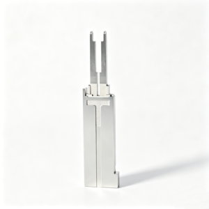
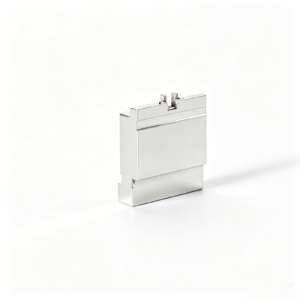
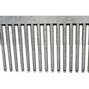
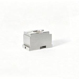
Representative Precision Components for Terminal-Block Tooling





Related Drawing-Based Components and RFQ







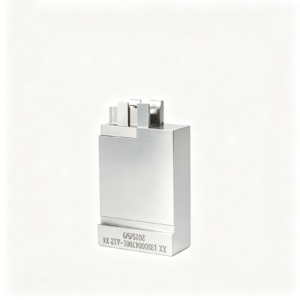
Why Teams Choose SUUXIANG for CNC Machined Terminal Blocks
Drawing-driven review, controlled process planning, and documented communication for custom terminal-block components.
Drawing-First Review
We review drawings, models, materials, critical dimensions, datums, and surface requirements before quotation discussions move toward production planning.
Practical DFM Input
Machining access, tolerance stack, burr-sensitive areas, and assembly interfaces are discussed early to identify manufacturability risks and decision points.
Integrated Process Routes
CNC milling, turning, EDM, precision grinding, fitting, and inspection are coordinated according to the component geometry and verified project requirements.
Inspection Planning
Critical-to-quality features and inspection methods are defined against the drawing, helping align measurement evidence with the agreed order requirements.
Revision Visibility
Controlled communication keeps drawing revisions, manufacturing questions, and delivery information visible as terminal-block projects progress through production.
Traceable Coordination
SUUXIANG supports clear exchange of material, heat-treatment, quantity, quality, and delivery requirements for more accountable sourcing decisions.
Terminal Block and Precision Component Families
Drawing-driven process routes for terminal blocks, connector tooling, mold components, and custom parts with review of critical dimensions before production.

CNC Machining Services
Precision CNC machining services for drawing-based terminal blocks, mold components, and custom parts. Process planning considers material, critical dimensions, datums, tool access, surface requirements, quantity, and inspection needs before quotation.
Upload a Drawing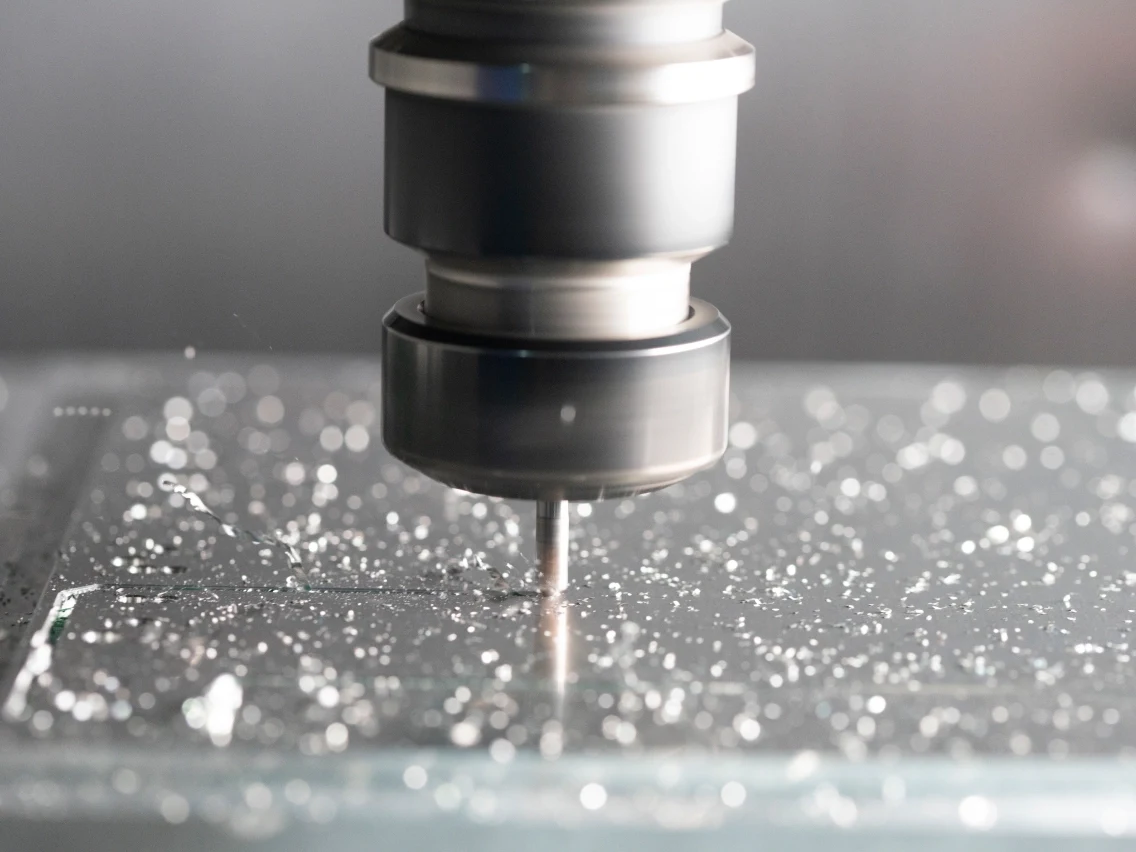
CNC Milling
Custom CNC milling services for prismatic parts, mounting features, pockets, channels, and connector-related geometries. Review should confirm datum setup, cutter access, internal-corner limits, wall rigidity, and tolerance priorities.
Upload a Drawing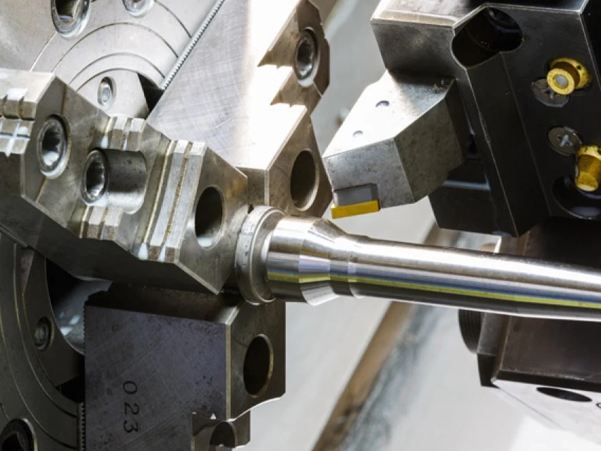
CNC Turning
Precision CNC turning services for shafts, pins, sleeves, bushings, threaded features, and rotational connector components. Drawings should identify functional diameters, runout relationships, surface requirements, material condition, and inspection points.
Upload a Drawing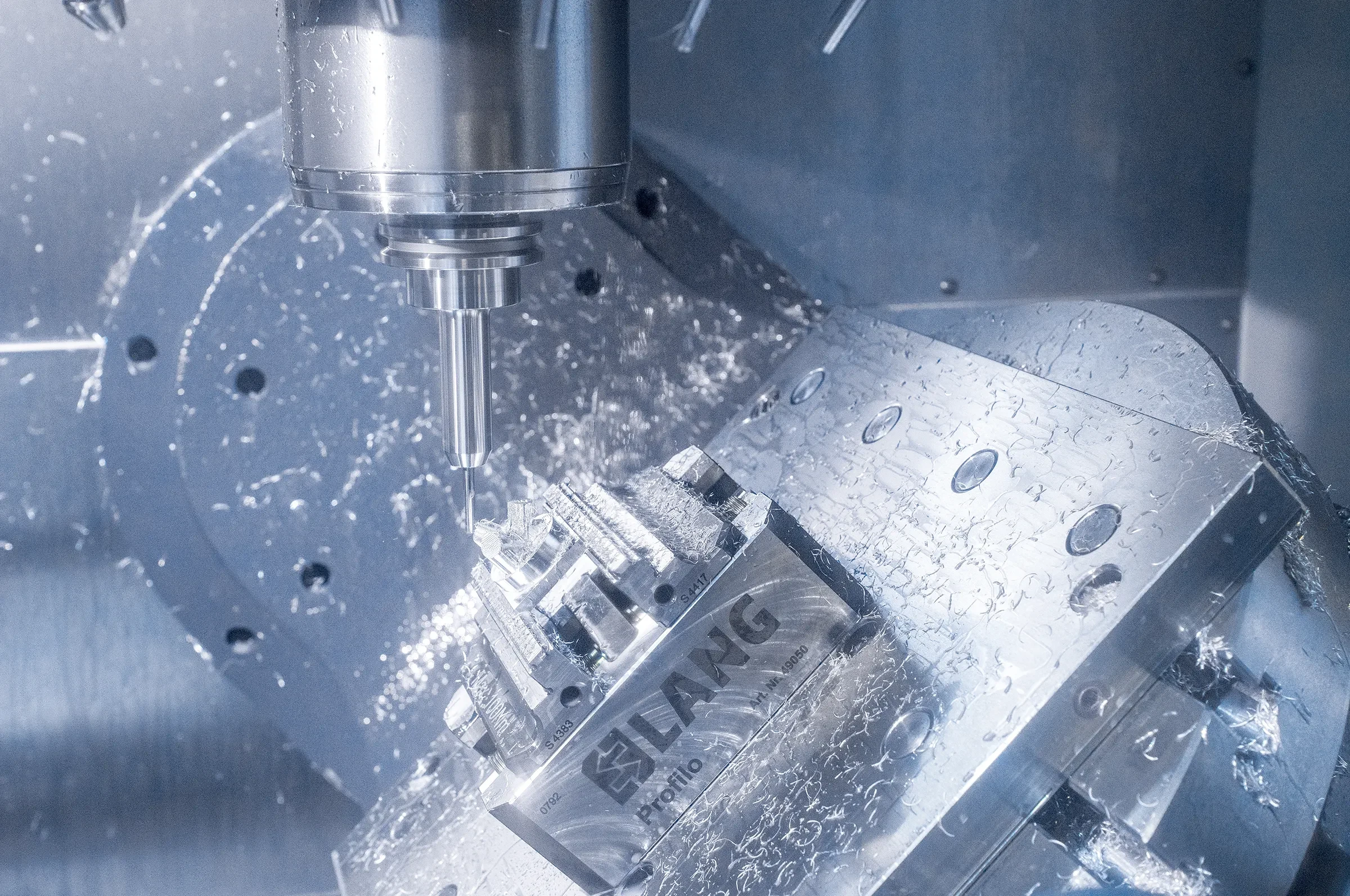
5-Axis Machining
5-axis CNC machining supports complex faces, angled holes, multi-side features, and reduced repositioning on suitable components. A drawing review assesses access, workholding, datum transfer, tool reach, and whether simultaneous machining is warranted.
Upload a Drawing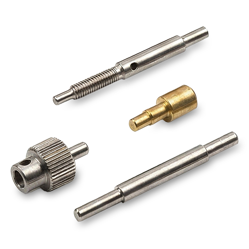
Swiss & Micro Machining
Swiss machining and micro machining support small-diameter pins, sleeves, contacts, and miniature precision parts where concentricity and feature relationships matter. Feasibility depends on material, geometry, length-to-diameter ratio, tolerances, and inspection method.
Upload a Drawing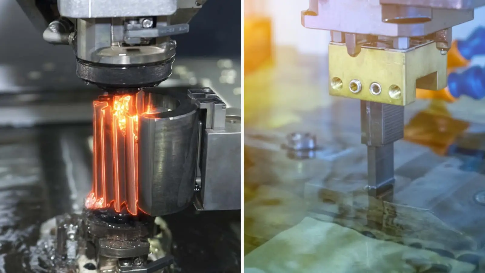
Wire & Sinker EDM
Wire EDM and sinker EDM services address hardened materials, narrow slots, sharp internal geometry, fine profiles, and inaccessible features. Process planning reviews wire path, electrode strategy, corner conditions, recast-layer considerations, and finishing requirements.
Upload a Drawing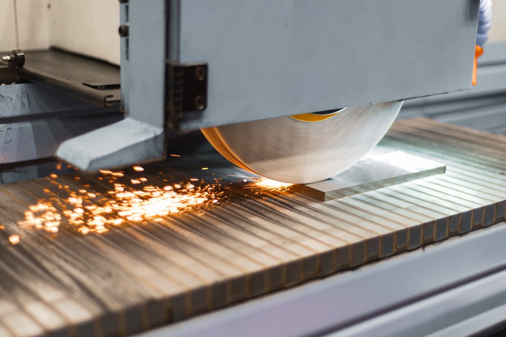
Precision Grinding
Precision surface and profile grinding supports flatness, parallelism, thickness control, profile accuracy, and final stock removal after machining or heat treatment. Grinding allowance, datum condition, hardness, and inspection criteria should be defined early.
Upload a Drawing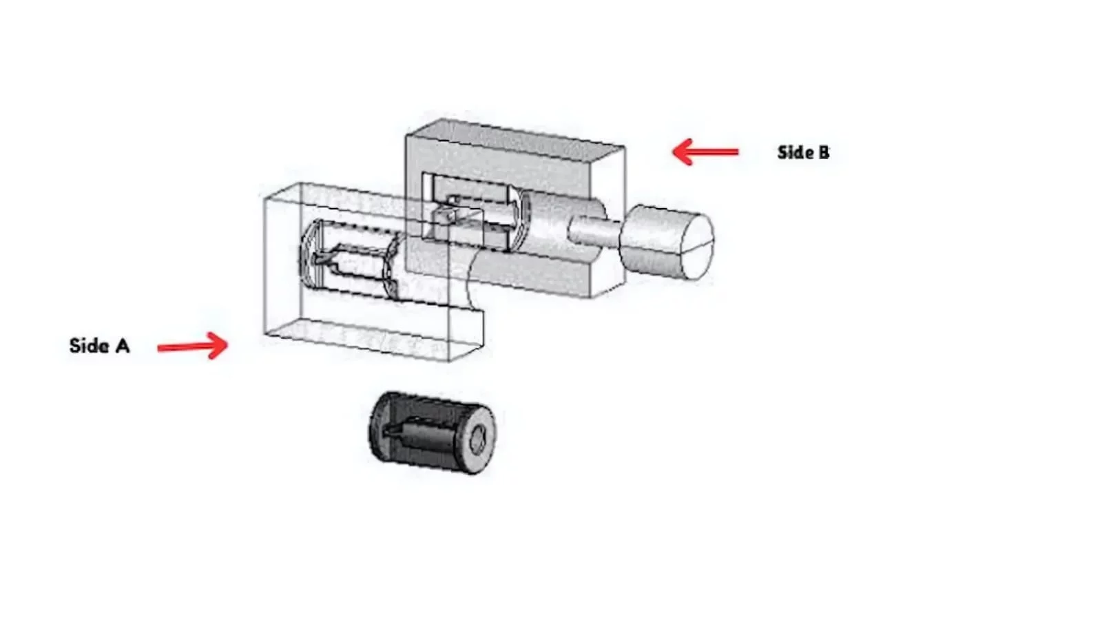
Mold Core & Cavity Inserts
Precision mold core and cavity inserts are manufactured from drawings for injection and related tooling applications. Review focuses on parting surfaces, cooling interfaces, shutoffs, material and heat treatment, EDM needs, grinding stock, and critical molded-feature dimensions.
Upload a Drawing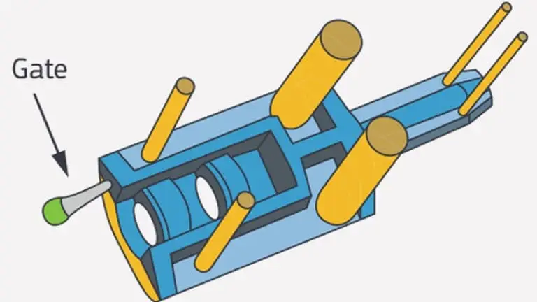
Ejector & Ejection Components
Ejector pins, sleeves, and ejection components are configurable to the drawing, application, and mold architecture. Specify diameters, fits, stroke-related features, material condition, surface requirements, and mating-component relationships for a practical review.
Upload a Drawing
Core Pins, Guide & Locating Components
Core pins, guide pins, and locating components require controlled relationships between functional diameters, shoulders, seating faces, and mating holes. SUUXIANG reviews fit strategy, material and treatment requirements, runout, and inspection priorities from the drawing.
Upload a Drawing
Slides, Lifters, Gates & Mold Accessories
Mold slides, lifters, gates, and accessories are supplied as drawing-based components rather than assumed catalog items. Production planning considers travel interfaces, shutoffs, guide surfaces, wear conditions, machining access, fitting requirements, and dimensional control.
Upload a Drawing
Connector Mold Components
Precision connector mold components support connector-product tooling where pitch, cavity alignment, fine features, and repeatable relationships are central. A technical review identifies critical dimensions, material condition, EDM or grinding requirements, and inspection evidence needed.
Upload a Drawing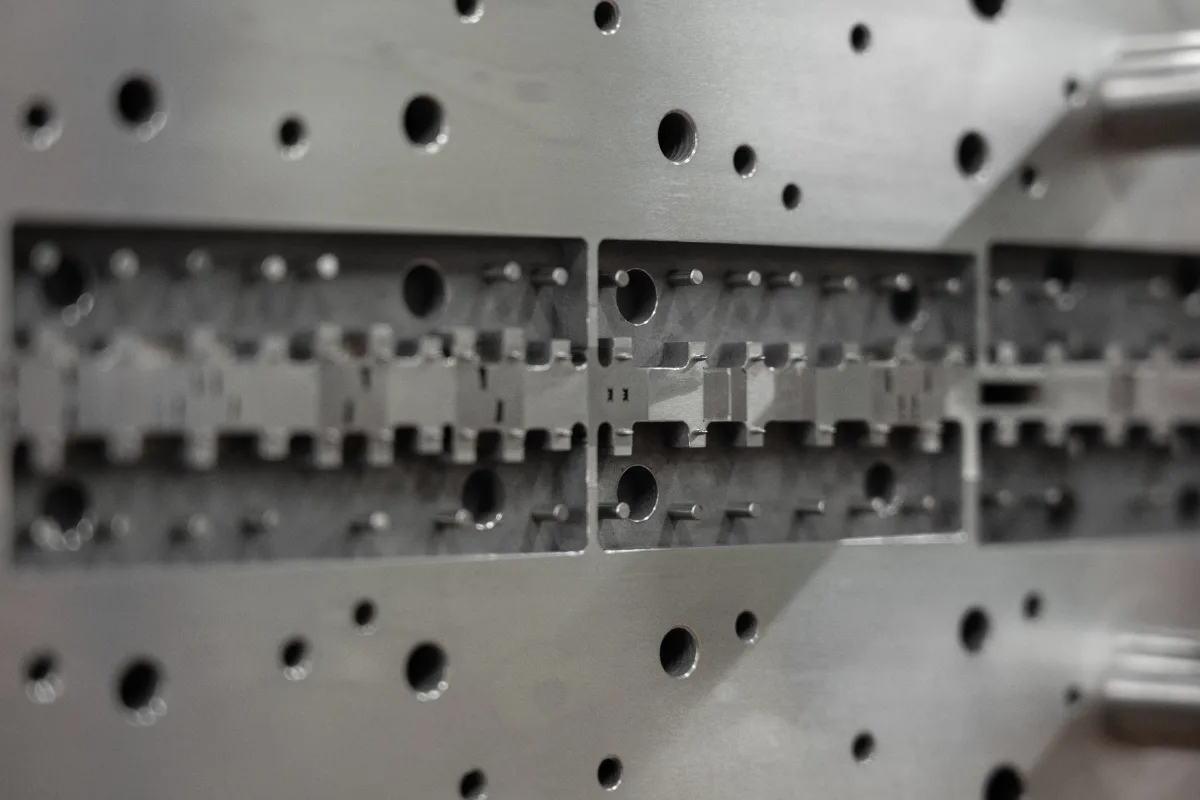
Stamping Die Components
Precision stamping die components are produced for drawing-defined die assemblies, including punches, inserts, guide elements, and formed profiles. Process selection considers tool steel condition, cutting edges, wire EDM strategy, grinding allowances, mating fits, and measurement requirements.
Upload a Drawing
Injection, MIM, CIM & Overmolding Tooling
Injection, MIM, CIM, and overmolding tooling components are evaluated within verified production scope. Review includes material behavior, molded-feature requirements, gating and shutoff geometry, insert interfaces, heat-treatment sequence, finishing, and inspection planning.
Upload a Drawing
Machining Materials
CNC machining materials are selected against drawing requirements, application loads, corrosion exposure, electrical or thermal needs, machinability, and downstream treatment. Confirm the exact grade, material condition, traceability needs, and approved substitutions before release.
Upload a Drawing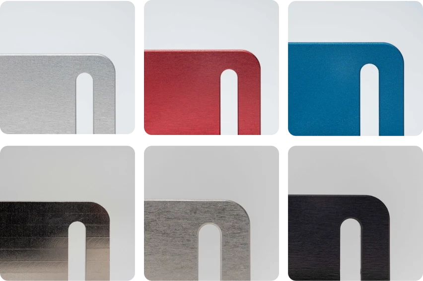
Surface Finishes & Heat Treatment
Surface finishing and heat treatment are planned around functional surfaces, hardness requirements, corrosion protection, wear behavior, dimensional change, and final tolerances. Define masking, grinding sequence, finish measurement, and post-treatment inspection expectations in the RFQ.
Upload a Drawing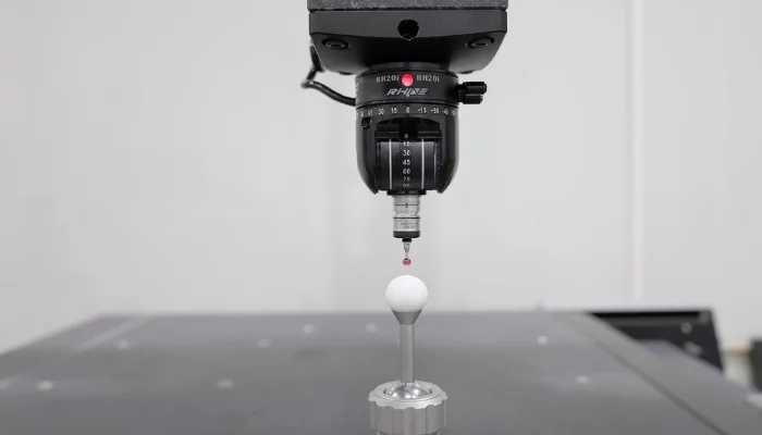
Quality, Metrology & Documentation
Precision inspection, metrology, and quality documentation are aligned to the order and verified inspection plan. Identify critical dimensions, datum scheme, measurement method, report format, sampling expectations, material records, and revision status before production.
Upload a Drawing
Prototyping & Low-Volume Production
Rapid prototyping and low-volume manufacturing support drawing-based evaluation, fit checks, engineering changes, and controlled initial builds. Submit the drawing, model, quantity, material, quality priorities, target date, and mating-component context for feasibility review.
Upload a DrawingMaterials for CNC Machined Terminal Blocks
High-Conductivity Copper
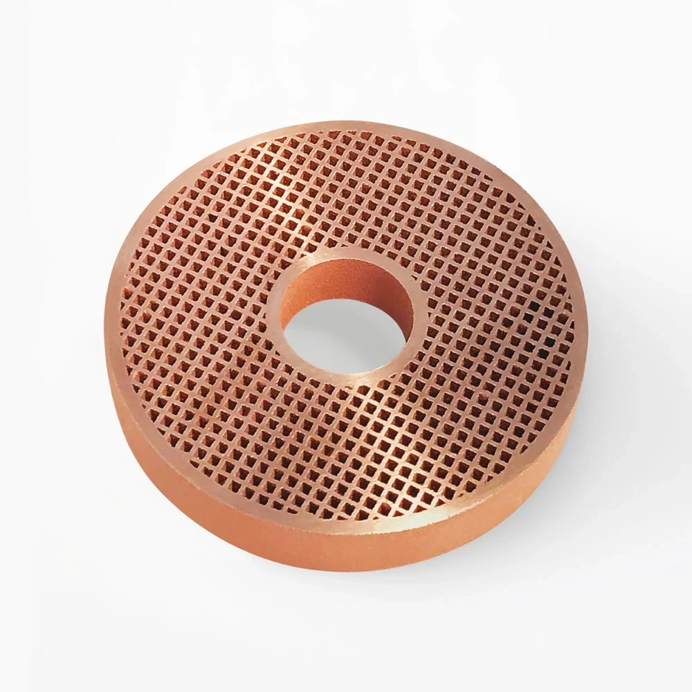
Selected where electrical and thermal conduction are central to the design. Copper suits current-carrying contact bodies and busbar-style features; soft, ductile stock requires burr-control planning around threads, edges, and contact faces.
Aluminum Alloys
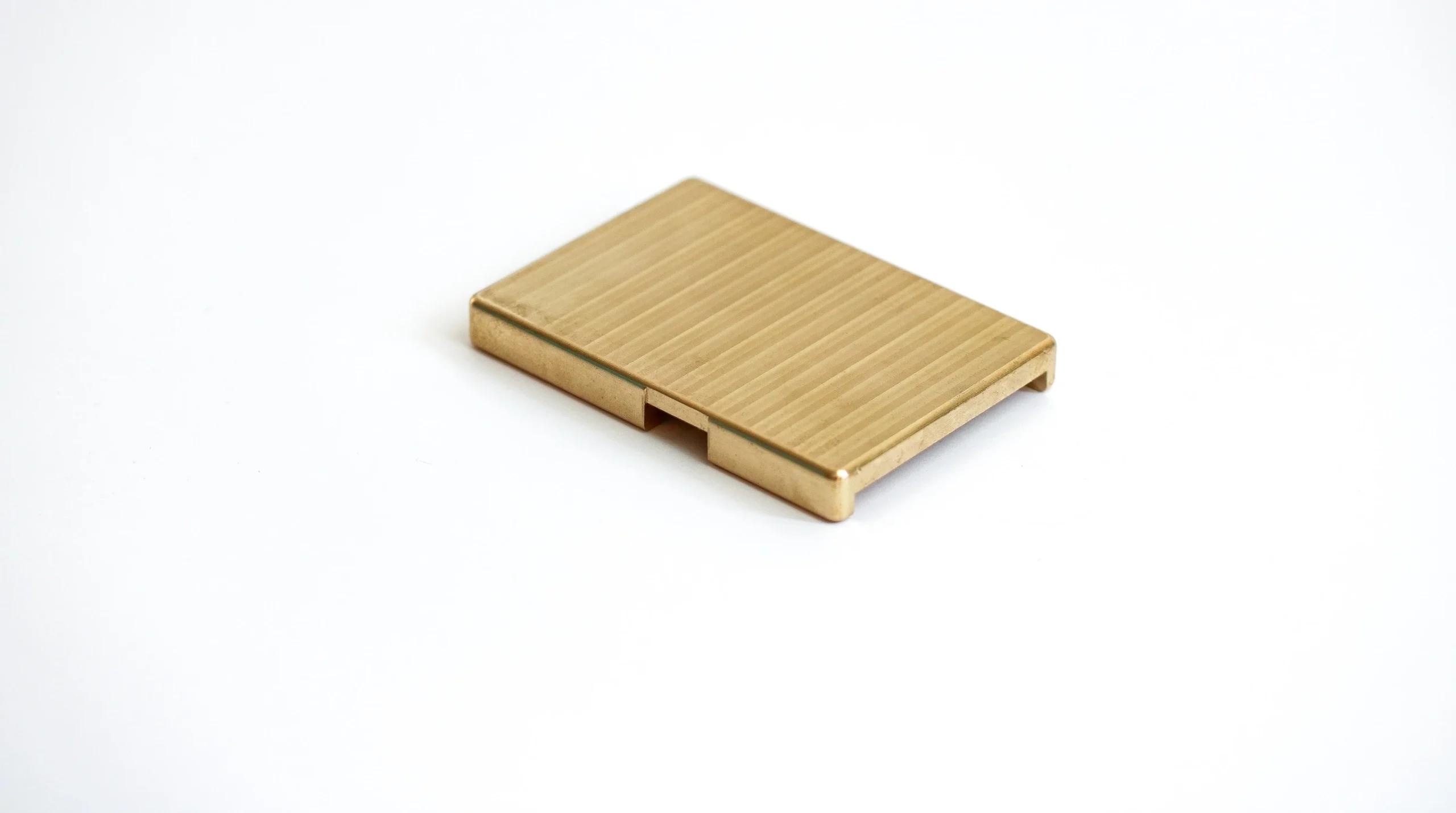
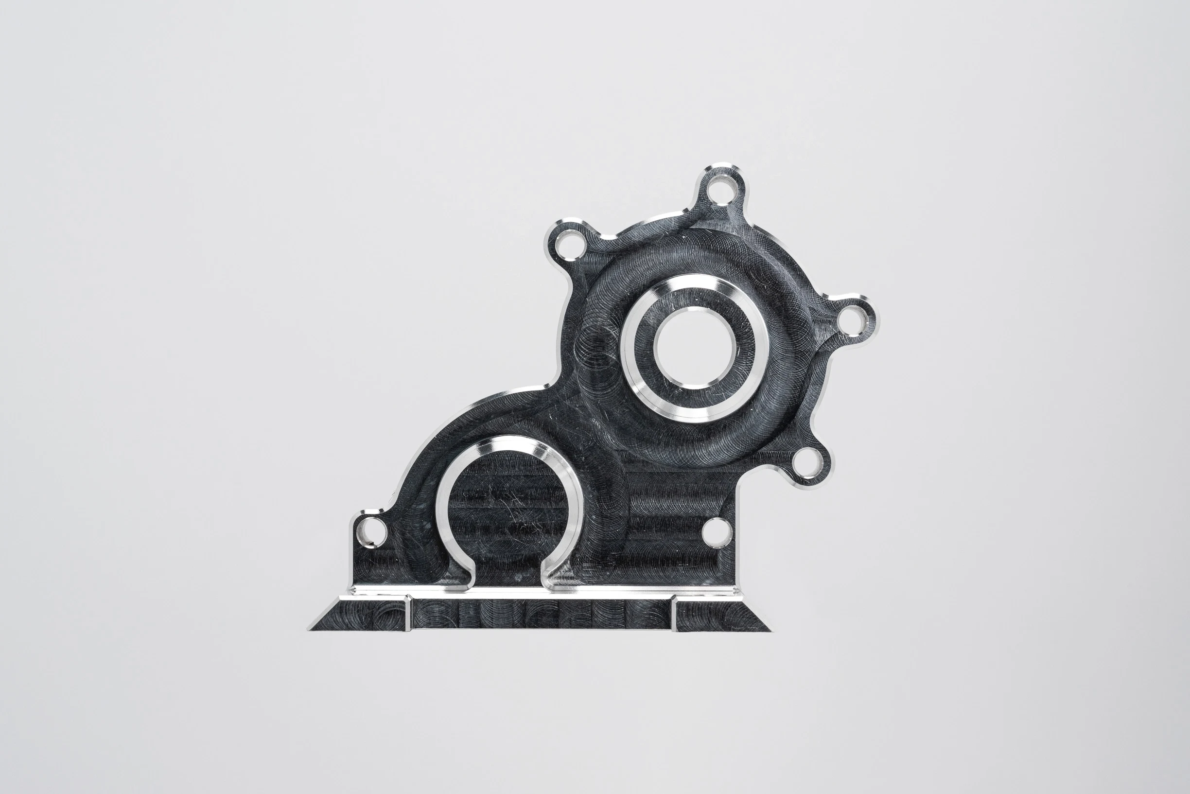
Used when lower component mass, structural stiffness, or efficient machining is important. Aluminum may suit housings, mounting bodies, and non-contact structures; specify alloy, finish, isolation needs, and environmental exposure in the drawing.
Stainless Steel
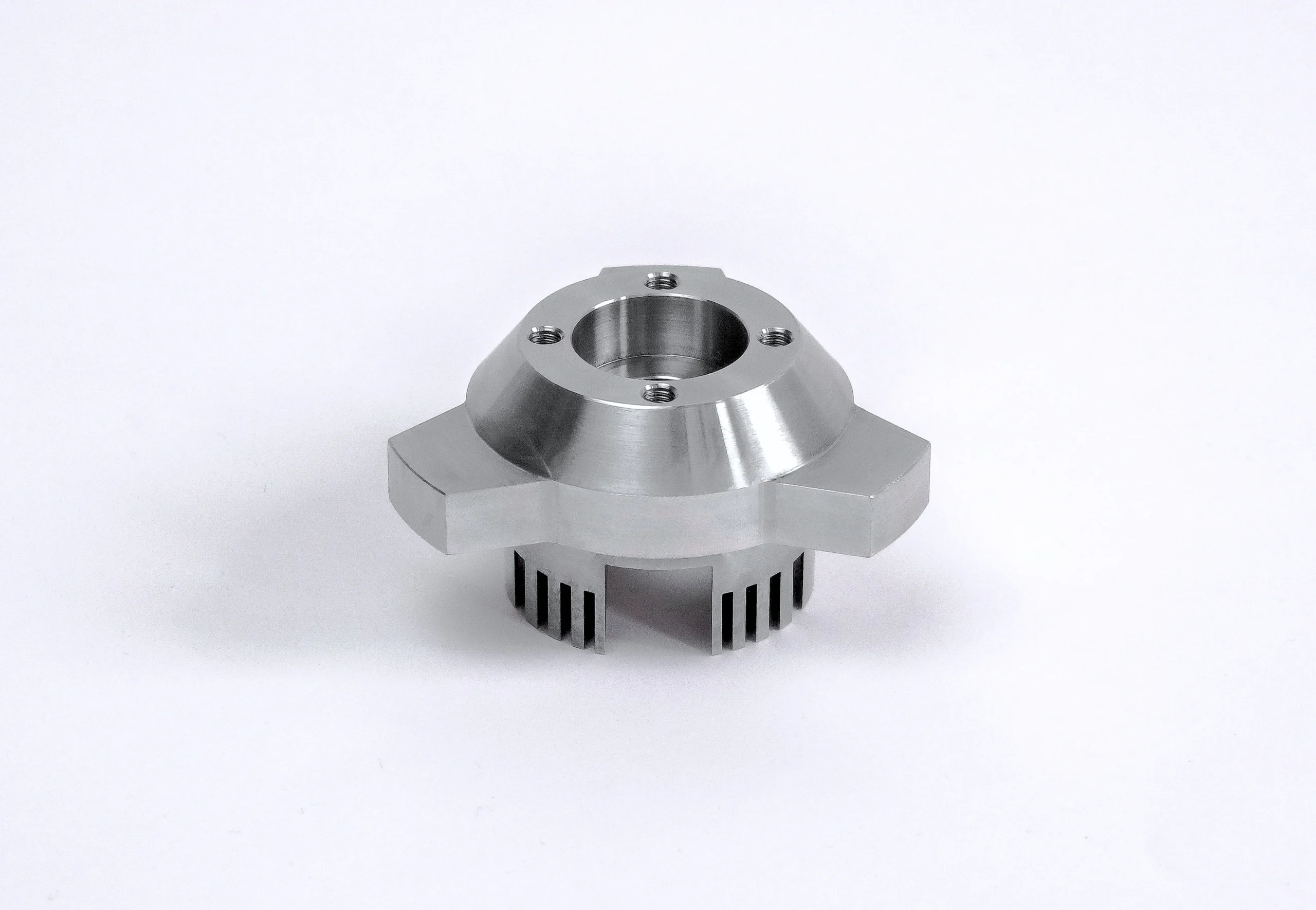
Considered for mechanically loaded or corrosion-exposed brackets, fasteners, and terminal-block support parts. Its higher strength and corrosion resistance can be useful, while machining access, thread design, and surface condition need review.
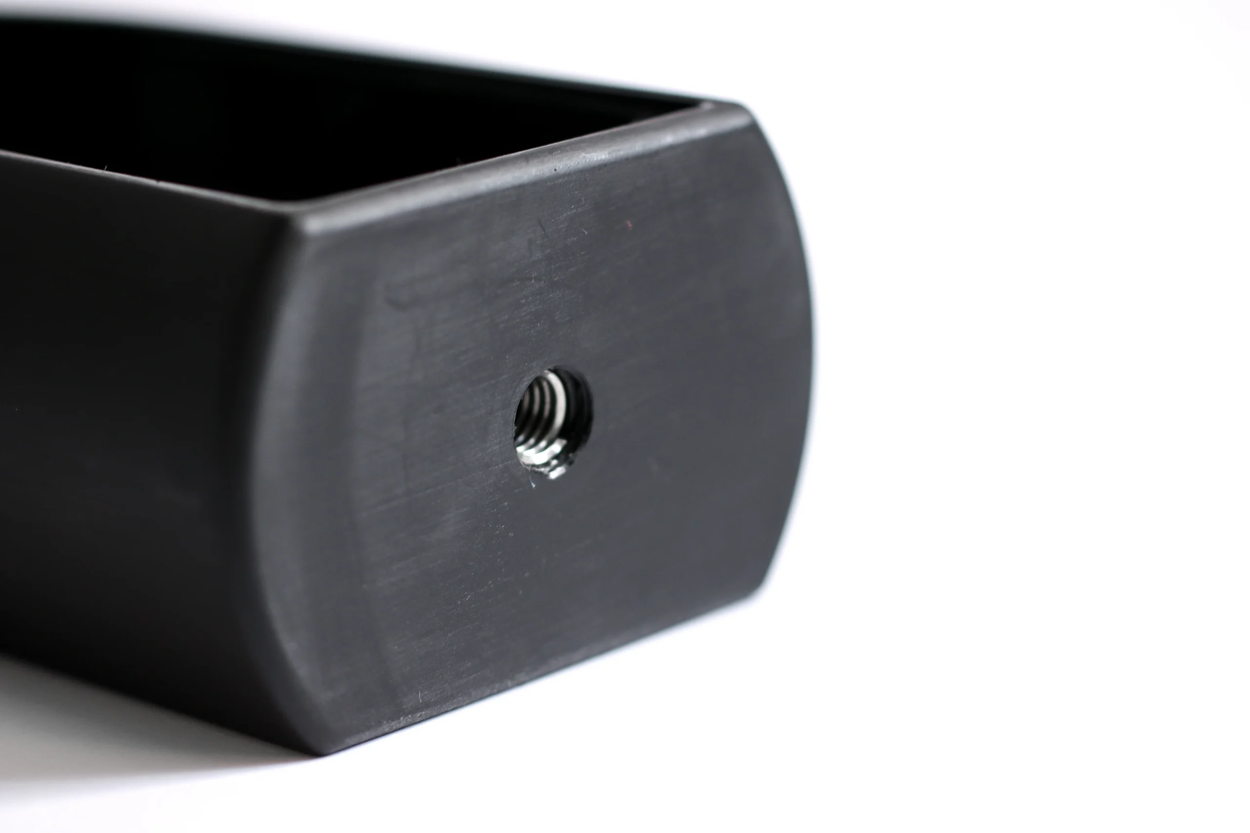
Engineering Plastics
Suitable for insulating bodies, separators, and protective features when the application supports a polymer solution. Resin choice should be driven by temperature, dielectric needs, flame requirements, dimensional stability, and assembly interface.
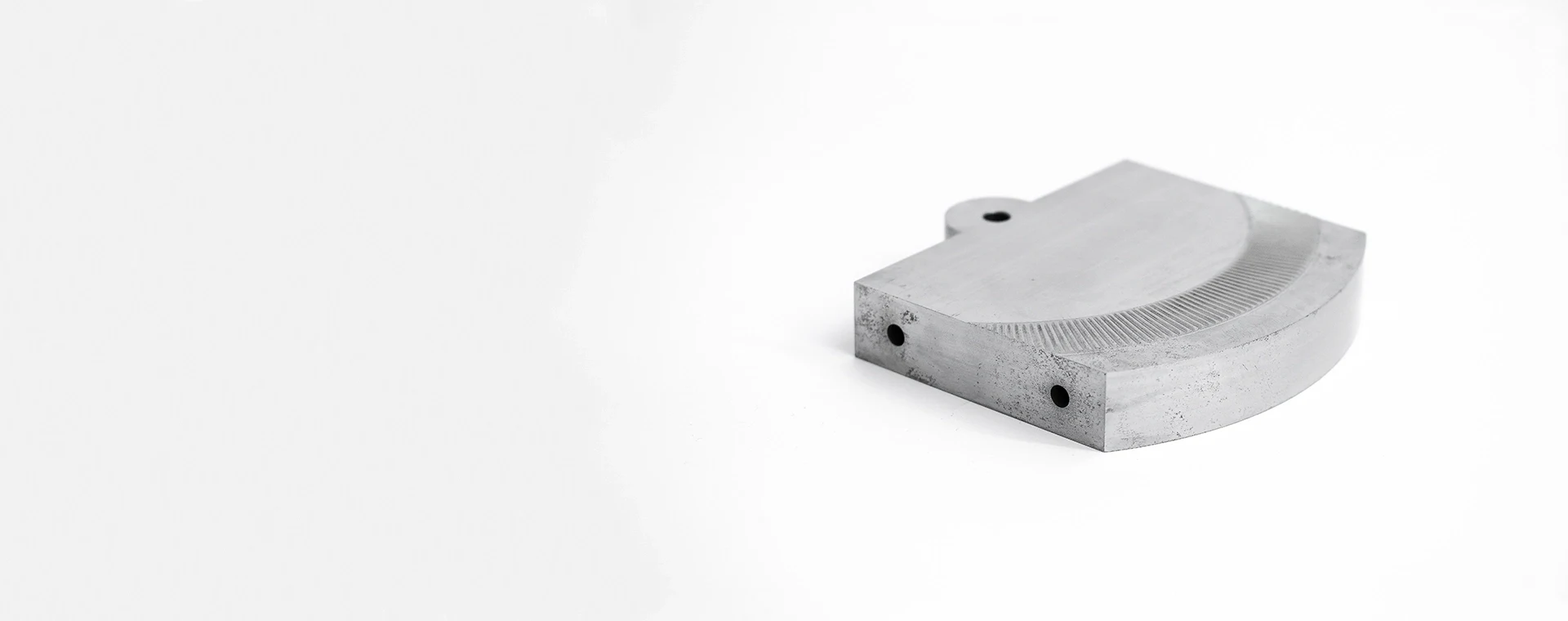
Tool Steel
Typically selected for connector tooling, forming elements, and precision production components rather than conductive terminal paths. Grade, heat-treatment sequence, grinding stock, EDM strategy, and critical-dimension inspection should be defined early.
CNC Machined Terminal Blocks: Supported Process Routes
CNC Milling
Milling creates faces, pockets, mounting patterns, channels and threaded features in terminal-block components. Tool access, datum strategy and burr-control requirements are reviewed before a machining route is confirmed.
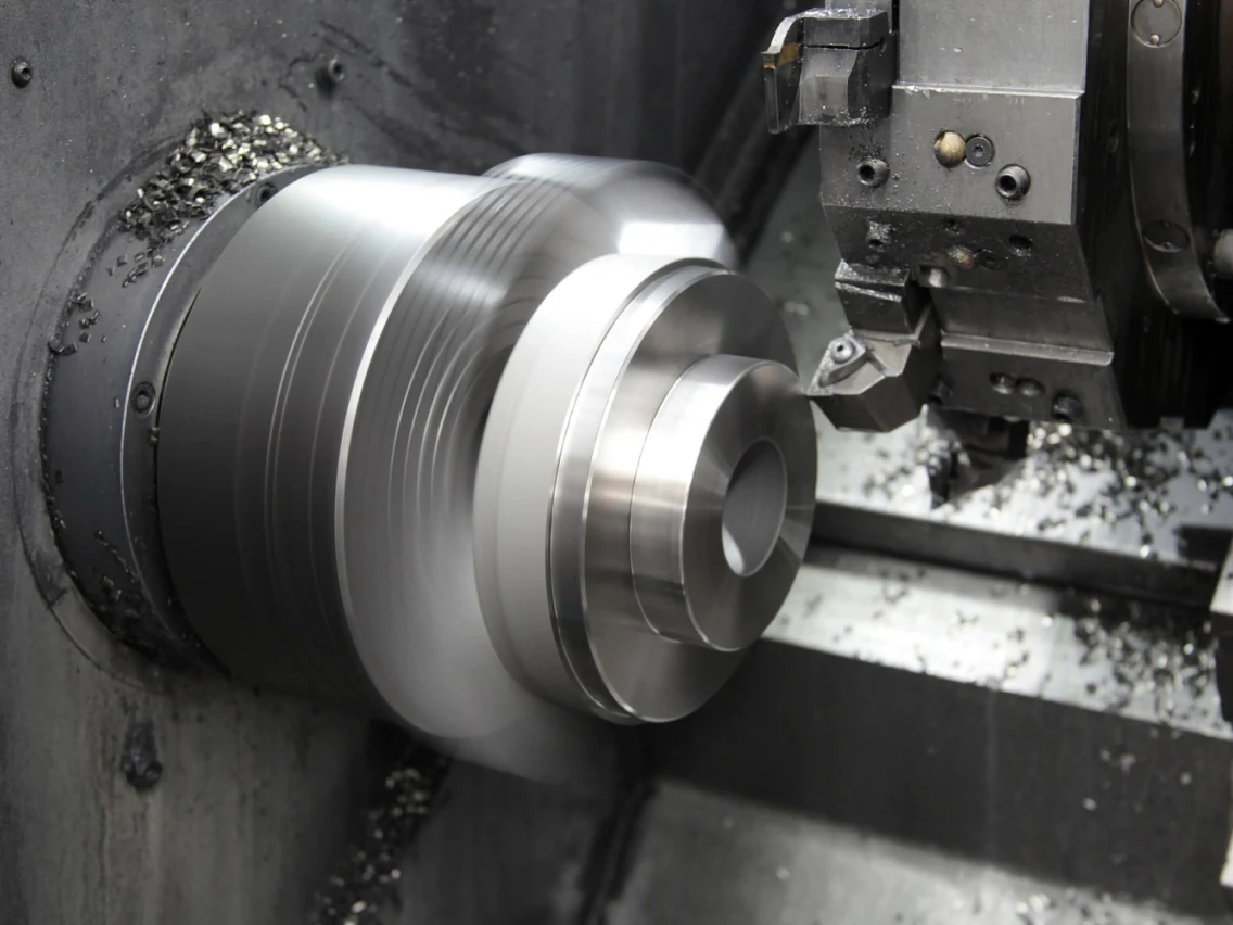
CNC Turning
Turning supports round posts, sleeves, spacers, adapters and concentric threaded features used with connector assemblies. The process route considers concentricity, shoulder locations, thread specification and the relationship to mating parts.
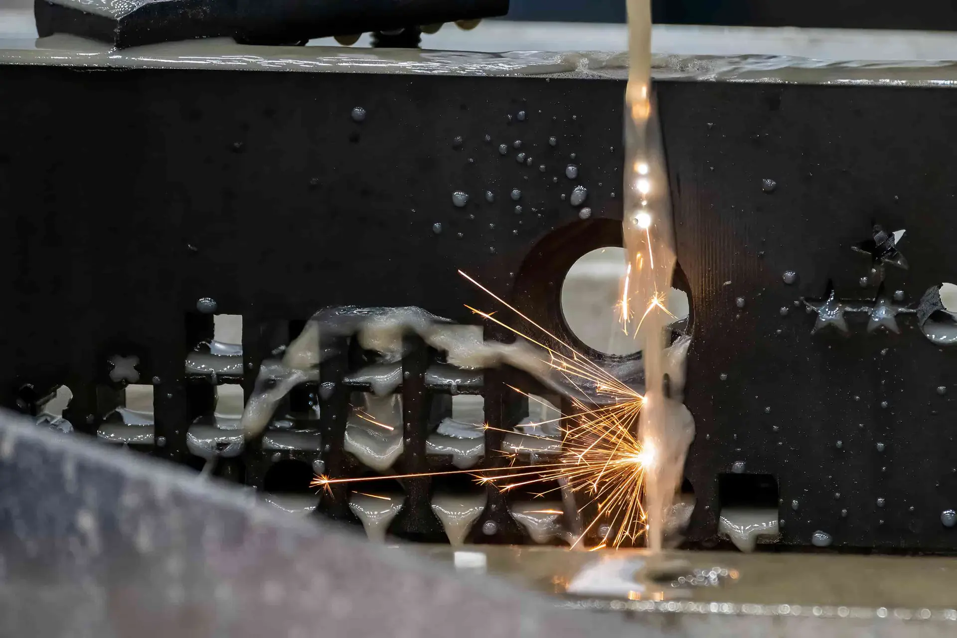
Wire EDM
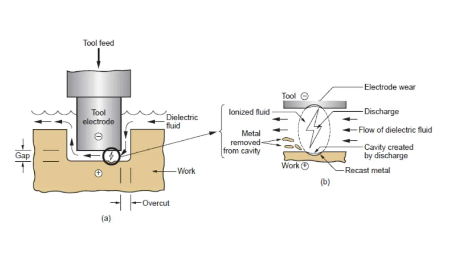
Wire EDM can produce precise profiles, narrow slots and hard-material features where conventional tool access is limited. Wire path, corner condition, allowance and datum references should be defined from the drawing.
Sinker EDM
Sinker EDM supports internal forms, deep details and features requiring electrode-based machining. Electrode strategy, surface requirements and downstream finishing are planned with the part geometry and critical dimensions in view.

Precision Grinding
Grinding refines critical flatness, parallelism, thickness and surface requirements after the appropriate machining or heat-treatment sequence. Grinding stock and measurement method are agreed before production planning begins.
Fitting and Inspection
Fitting verifies functional relationships between applicable components, while inspection checks drawing-defined dimensions and reporting needs. SUUXIANG aligns final records with the order, revision level and verified inspection plan.
CNC Machined Terminal Blocks: Hardware and Identification Options
Threaded Inserts
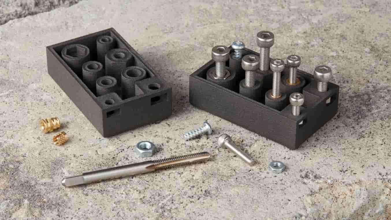
Specify inserts where repeated assembly calls for durable threads in the base material. Provide thread size, installation method, pull-out expectations and any torque or electrical-isolation requirements for review.

Locating Pins
Dowel, guide or alignment pins can establish repeatable position between terminal-block components and mating tooling. Define datum references, fit class, engagement length and whether pins remain removable after assembly.
Specified Fasteners
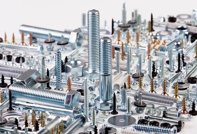
Screws, studs and clamping hardware may be supplied when they are defined by the drawing or bill of materials. Identify thread, material, finish, tightening requirement and mating-part interface.

Contact Features
Machined contact pads, threaded connection points and conductor interfaces should be reviewed against the mating component. Share critical flatness, burr-control, surface-finish and corrosion-protection requirements before process planning.
Part Identification
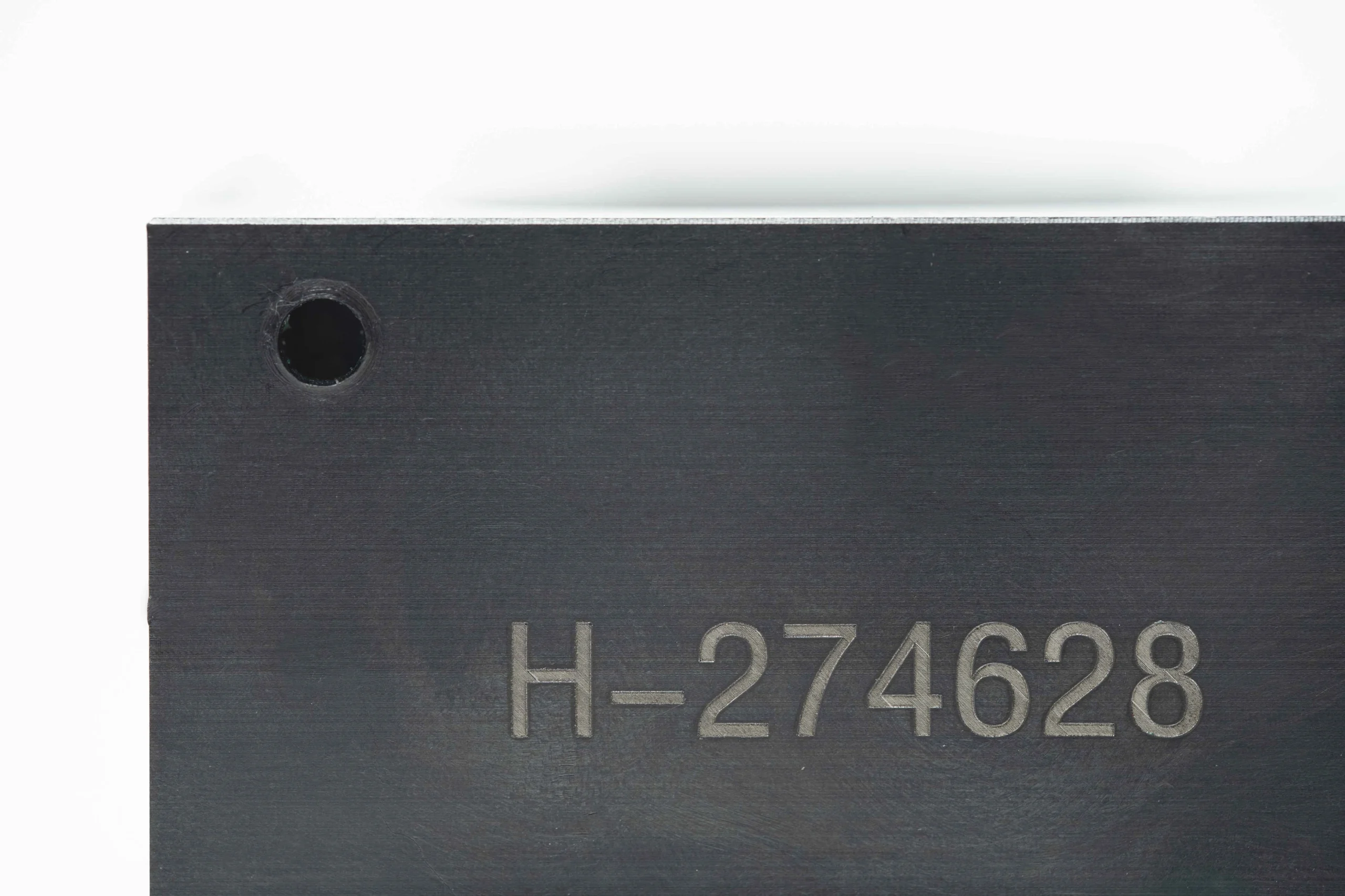
Part numbers, revision marks and lot-identification areas can support assembly control and traceability. Specify marking content, location, legibility requirement and any restriction on methods that could affect the contact surface.

Protective Packaging
Project-specific packaging can protect critical faces, threads and conductive surfaces through shipment. State handling risks, separation needs, cleanliness expectations, quantity per pack and any labeling or documentation requirements.
About SUUXIANG: Drawing-Driven Precision Manufacturing
SUUXIANG is the sole public-facing brand of Dongguan SuuXiang Precision Mold Co., Ltd., established in 2010 in Chang’an Town, Dongguan, Guangdong, China. Founder and legal representative XiaoCheng Huang leads the company behind drawing-driven work for inspected CNC-machined parts, precision mold components, connector tooling and CNC-machined terminal blocks.
Our workflow combines CNC milling and turning, multi-axis machining, EDM, precision grinding, fitting and inspection. Before quotation or production, we review the drawing, critical dimensions, datums, material and heat-treatment requirements, machining access, surface priorities and inspection expectations to define a practical process route.
What distinguishes SUUXIANG is disciplined project control around the details that affect fit and verification: DFM feedback, machining and grinding allowances, electrode or wire-path strategy, revision visibility and order-specific inspection planning. Submit your drawing with quantity, quality requirements and target date for a focused manufacturing review.

CNC Machined Terminal Blocks: Controlled Production
DFM Before Commitment
SUUXIANG reviews drawings, models, material requirements, quantities and application context before quoting CNC machined terminal blocks. The discussion identifies critical dimensions, datums, tool access, surface priorities and potential tolerance-stack risks so the proposed route reflects the actual part requirement.
- Confirm critical-to-quality dimensions and datum scheme
- Review thread, contact-face and mounting-feature access
- Flag tolerance, burr-control and assembly risks early
- Align material, heat treatment and inspection expectations

Multi-Axis Machining Planning
Machining strategy is planned around feature orientation, clamping stability and relationship control between holes, pockets and contact surfaces. CNC milling, turning and multi-axis work can be combined where the verified project scope supports the geometry, reducing unnecessary handling between critical operations.
- Plan setups around functional feature relationships
- Assess milling, turning and multi-axis process fit
- Control stock condition before secondary operations
- Keep drawing revisions visible through planning
EDM and Grinding Strategy
Where geometry, hardness or finish requirements make conventional cutting unsuitable, SUUXIANG evaluates wire EDM, sinker EDM and precision grinding within the production plan. Electrode access, wire paths, grinding allowance and heat-treatment sequence should be resolved before manufacturing begins.
- Evaluate EDM access for narrow or internal features
- Define grinding stock and final-surface sequence
- Consider heat treatment before finishing operations
- Review edge conditions near functional interfaces
Inspection With Traceability
Inspection planning follows the agreed drawing revision and identified critical features rather than a generic checklist. SUUXIANG aligns measurement methods, reporting needs and final documentation with the order, helping procurement and quality teams maintain clear records from drawing review through delivery.
- Link inspection points to critical drawing requirements
- Agree reporting and documentation needs in advance
- Maintain revision visibility during project coordination
- Verify final records against the inspection plan
CNC Machined Terminal Blocks: Beyond Generic Quotes
Compare the controls that help translate terminal-block drawings into an inspectable manufacturing plan.
← Swipe left or right to view →
CNC Machined Terminal Blocks: From Drawing Review to Shipment
A drawing-driven workflow keeps critical dimensions, process decisions, inspection expectations and delivery requirements visible before production commitments are made.
Review RFQ Package
We review drawings, models, material requirements, quantity, application context, target date and inspection needs to identify missing information before quotation.
Confirm DFM Priorities
Critical dimensions, datums, tolerance stack, tool access, thread details and contact-surface requirements are discussed to establish a manufacturable process route.
Plan Material Process
The team aligns material, heat-treatment sequence, machining allowance and required CNC, EDM or grinding operations with the approved drawing revision.
Machine Critical Features
CNC milling, turning and multi-axis work produce accessible features; wire EDM, sinker EDM or grinding support geometry, finish and datum requirements where appropriate.
Inspect and Coordinate Delivery
Parts are checked against the agreed inspection plan, documented to match the order, then packed and scheduled with revision-controlled delivery coordination.
Start Your CNC Machined Terminal Blocks RFQ
Provide the drawing and the decision-critical requirements early so SUUXIANG can review manufacturability, plan inspection, and align the production route before commitment.
Send Drawings and Models
Upload the current 2D drawing and, when available, 3D model. Identify the revision level and include mating-component context that may affect interfaces or assembly.
Define Material and Quantity
State the specified material, heat-treatment or finish requirements, requested quantity, and target delivery date. Flag any application conditions that influence material or process selection.
Mark Critical Requirements
Call out critical dimensions, datums, thread details, contact surfaces, surface requirements, and allowable burr conditions. Note functional relationships where tolerance stack or machining access matters.
Specify Inspection Expectations
Describe required inspection methods, reporting format, traceability needs, and acceptance criteria. SUUXIANG uses this information to align the inspection plan with the order requirements.
Review the Process Route
Discuss DFM findings, machining sequence, EDM or grinding needs, revision control, and delivery coordination before production commitments are made for your CNC machined terminal blocks.
Quality Documentation for CNC Machined Terminal Blocks
Customer Feedback on CNC Machined Terminal Blocks
Approved customer feedback for CNC machined terminal blocks will be published after the customer, application details, measurable results, and publication permission have been verified by SUUXIANG.
A verified project summary will be added here when the customer approves publication of the drawing scope, inspection outcome, delivery context, and relevant manufacturing details.
SUUXIANG will publish only approved customer feedback supported by identifiable project context and verifiable outcomes, so engineering and sourcing teams can assess the relevance of each example.
CNC Machined Terminal Blocks FAQ
Practical answers for engineering, quality and procurement teams preparing a drawing-driven terminal-block project.
What information should I send for a CNC machined terminal blocks RFQ?
Can SUUXIANG manufacture custom CNC machined terminal blocks from my drawing?
Is there a minimum order quantity for CNC machined terminal blocks?
Can I order samples before a production release?
How long does it take to produce custom terminal blocks?
Can I receive inspection reports with my order?
How are drawings and intellectual property handled for CNC machined terminal blocks?
What payment and shipping details should be confirmed before ordering?
The Complete Buyer’s Guide to cnc machined terminal blocks
Use this practical decision framework to specify materials, critical features, finishing, quality controls, and supplier requirements for drawing-based terminal-block projects while avoiding costly sourcing and manufacturability mistakes.
1. What Are cnc machined terminal blocks?
1. CNC machined terminal blocks are drawing-based conductive connection components milled or turned from solid stock, commonly with threaded ports, mounting faces, and defined contact interfaces. They route current or provide controlled attachment points in power distribution, control systems, battery connections, and custom connector assemblies.
2. They are not the same as standard insulated terminal blocks, which usually combine standardized metal contacts with a polymer body for panel wiring. They also differ from stamped terminals, formed from sheet, and molded housings, which provide insulation, retention, or connector geometry rather than the machined conductive path.
3. Machining is justified when the drawing calls for nonstandard port spacing, intersecting features, precision mounting datums, or interfaces that must align with mating hardware. It is also a practical route for prototypes and low-volume builds where dedicated stamping or molding tooling is not yet warranted.
2. How Terminal Block Manufacturing Evolved
Three production routes still coexist: molding makes insulating housings, stamping suits repeatable metal forms, and CNC serves drawing-specific conductive parts where geometry or change control matters.
CAD data converts functional requirements into controlled hole locations, threads, datum-related faces, pockets and mounting features. CNC milling addresses prismatic blocks, turning produces round posts or adapters, and multi-axis access can machine several faces with fewer re-fixtures; inspection should verify the drawing-defined features and reporting plan. https://www.tuofamachining.com/news/busbar-terminal-block-cnc-machining-and-surface-finishing-for-reliable-electrical-connections-384105.html
One sourcing decision separates prototype and specialized assemblies from high-volume standardized designs: CNC can support revisions and complex features without dedicated stamping dies or molding tools. It complements, rather than replaces, molding and stamping; buyers should specify which elements are machined, formed, molded, or supplied as mating components before quotation.
3. Types of cnc machined terminal blocks
Six configurations cover most drawing-based requests for cnc machined terminal blocks. Select the interface and mounting scheme first, then define the uninterrupted conductive path, insulated boundaries, and inspection datums.
| Configuration | Typical Interface | Drawing Focus |
|---|---|---|
| Busbar distribution | Lugs or tapped takeoffs | Pad geometry, section, mounting datum |
| Screw clamp | Stripped wire and screw | Wire entry, thread, tool access |
| Stud or ring terminal | Lug, stud, nut | Thread, shoulder, rotation control |
| Multi-port connector | Multiple cable or plug ports | Port pitch, polarity, clearance |
| Insulated insert | Conductor within housing | Isolation gaps, retention, assembly datum |
| Hybrid milled-turned | Block with posts or adapters | Concentricity, joints, assembly sequence |
Busbar And Distribution Blocks
Busbar blocks join cable lugs, blades, or tapped takeoffs on a common conductive body. Show pad locations, hole pitch, current-path cross-sections, mounting faces, and keep-out zones for tools.
Clamp And Stud Interfaces
Screw-clamp blocks retain stripped conductors through a screw, pressure element, and wire entry. Stud blocks accept ring terminals; specify stud thread, shoulder, nut engagement, lug orientation, and anti-rotation feature.
Multi-Port And Hybrid Designs
Multi-port blocks distribute one feed to several outputs, while insulated inserts separate conductive hardware from a housing. Hybrid machined-and-turned designs combine milled bodies with posts, spacers, or threaded adapters; datum relationships between components drive fitting and inspection.
4. Materials for cnc machined terminal blocks
Four material families cover most drawing-based choices for cnc machined terminal blocks. Separate the current-carrying body from screws, covers, brackets, and housings before comparing metals.
| Material | Conductivity | Strength And Machining | Weight, Cost, Typical Fit |
|---|---|---|---|
| Copper | Highest of these options | Soft; burr control matters | Heavy; higher cost; current-carrying bodies |
| Brass | Moderate | Stronger threads; readily machined | Heavy; moderate-to-higher cost; terminals and inserts |
| Aluminum | Lower than copper | Good machinability; moderate strength | Light; cost varies; conductive structures or housings |
| Stainless Steel | Low | High strength; harder to machine | Heavy; higher machining cost; screws, brackets, housings |
Conductive Body Selection
Copper is the default when electrical and thermal conduction dominate; specify alloy, temper, and contact-area requirements. Brass trades conductivity for stronger threads and generally easier chip control.
Aluminum reduces mass and may suit conductive structures where cross-section can offset lower conductivity. Stainless steel is normally a structural choice, not the primary current path.
Selection Inputs
Five inputs govern final selection: current, allowable temperature rise, mating material, environment, and applicable product requirements. Identify dissimilar-metal interfaces, plating, clamping force, and corrosion exposure on the drawing or RFQ.
Two separate part callouts are often clearer than one compromise alloy: conductive body material and structural-hardware material. Confirm the proposed route during drawing review.
5. Custom Features and Surface Finishes
Drawing-defined features determine both machining access and assembly fit for cnc machined terminal blocks. Specify functional geometry separately from cosmetic expectations before a process route is selected.
| Finish | Typical Drawing Need | Caution |
|---|---|---|
| Deburr | Edge-break limit | Protect contact edges |
| Tin plate | Coverage and masking | Define contact areas |
| Nickel plate | Thickness range | Check mating design |
| Anodize | Color and masked faces | Aluminum only |
| Passivate | Hardware material | Not a conductive coating |
Define Functional Features
Port count, hole pitch, tapped threads, studs, mounting faces, slots, and chamfers should be dimensioned from identified datums.
Assembly-ready drawings should state thread class, engagement depth, counterbore details, and whether installed hardware is customer-supplied.
Call Out Contact Zones
Contact zones should be bounded on the drawing and linked to flatness, roughness, cleanliness, or burr-direction requirements.
Coating notes should define coverage, masked areas, thickness range, and acceptable visual variation; plating does not automatically improve every mating interface.
Select Finish By Function
Deburring and cleaning remove machining residue before inspection or downstream treatment. Tin or nickel plating may be specified for defined service conditions.
Anodizing applies to appropriate aluminum features, while passivation is relevant to nonconductive stainless hardware; confirm compatibility with the electrical design.
6. Critical Quality Elements for Reliable Connections
Two datums can control a terminal block more reliably than dimensions chained from cosmetic edges. Critical-to-function features should be flagged on the drawing so inspection follows the mating and clamping condition.
Datums And Feature Location
One primary mounting datum and two secondary locating faces establish a repeatable inspection frame. Locate holes, slots, and contact pads from that frame; apply position tolerance where assembly alignment matters.
0.01 mm is not automatically appropriate: choose tolerances from mating clearance, torque load, and process capability evidence.
Threads And Contact Faces
GO and NO-GO gauges verify thread acceptance faster than a diameter reading alone. Specify thread class, depth, runout needs, and any no-plating zone.
Ra requirements, flatness, burr limits, edge breaks, cleanliness, and plating coverage belong at each functional contact face—not in a general note.
Request Traceable Evidence
First-article records should link ballooned drawing characteristics to measured results and revision level. Ask for dimensional reports, thread-gauge results, plating evidence when specified, and agreed visual acceptance standards.
100% inspection is meaningful only when the report identifies the checked features, method, sample quantity, date, and lot traceability.
7. Choosing a cnc machined terminal blocks Supplier
Two supplier reviews should happen before PO release: engineering checks process feasibility, while quality and procurement confirm evidence flow. For cnc machined terminal blocks, compare the drawing-review response, not only the quotation.
| Review Area | Ask The Supplier | Evidence To Request |
|---|---|---|
| DFM | How are risks escalated? | Marked drawing and process notes |
| Traceability | How is material linked? | Lot record and certificates |
| Inspection | How are CTQs measured? | Inspection plan and report |
| Continuity | How are revisions controlled? | Revision log and approval |
Drawing Review And Process Route
First, ask for documented DFM feedback on datums, burr-sensitive contact faces, tool access, and thread callouts.
Second, confirm which features require CNC milling, turning, dedicated fixtures, or secondary deburring.
Material, Finish, And Inspection
Each lot should link the specified material and heat-treatment requirement to the part record.
Before release, define finish-source coordination, sampling, critical dimensions, measurement method, report format, and nonconformance handling.
Continuity And Document Control
One controlled revision should govern prototype, approval samples, and subsequent production.
Ask who acknowledges drawing changes, retains inspection records, communicates delivery risks, and verifies that fixtures remain suitable after revisions.
8. Common Buyer Mistakes to Avoid
Seven recurring RFQ gaps cause avoidable rework in cnc machined terminal blocks. Each is preventable when the drawing defines functional interfaces and the validation plan reflects the intended assembly.
Specify Functional Material
Material color is not a specification. State alloy or grade, temper, heat treatment, conductivity needs, and the current path; then identify every contact face and its required finish.
Control Edges And Plating
±0.01 mm tolerances on nonfunctional faces can add cost without improving performance. Apply tolerances from defined datums, call out burr direction and edge breaks, and specify plating type, thickness range, masked areas, and post-plate inspection.
Validate The Real Assembly
One approved loose sample does not confirm a working connection. Provide mating terminals, screws, washers, torque requirements, and enclosure constraints; validate representative assemblies for fit, seating, contact access, and revision-controlled inspection records.
9. From Drawing to Production Launch
One controlled launch begins before a purchase order: define the terminal block’s current path, mating interfaces, environment, quantity, and acceptance criteria. Assign each requirement to an accountable owner before DFM review starts.
Release The Engineering Package
Two files should travel together: a dimensioned 2D drawing and the native or neutral 3D model. Design owns datums, critical threads, contact faces, tolerances, approved material, plating, and revision identification.
One interface note should identify mating terminals, fastener torque requirements, insulation boundaries, and electrical test conditions. Manufacturing uses it to assess tool access, burr control, workholding, and inspection feasibility.
Close DFM And Quotation Assumptions
A documented DFM response should resolve inaccessible features, ambiguous tolerances, finishing sequence, and inspection method before quotation acceptance. Procurement owns commercial alignment; design and quality approve technical departures.
Three quotation assumptions deserve explicit confirmation: supplied material grade, lot quantity, and included verification records. SUUXIANG can then route machining, deburring, inspection, and delivery against the released package.
Approve First Articles And Control Changes
First articles should be checked against drawing dimensions and assembled with representative mating parts. Quality owns measurement acceptance; design validates fit and electrical assembly performance before production release.
Every revision requires a dated drawing or change notice, impact review, and written disposition of work in progress. Manufacturing maintains the released revision, inspection plan, and traceable order documentation.
10. cnc machined terminal blocks Pricing and Lead Time
3 commercial stages should be separated in a quotation: one-time engineering, recurring unit processing, and order-specific quality or logistics work. This avoids treating a 5-piece drawing check like a 500-piece repeat batch.
2 drawing files—a dimensioned PDF and a STEP model—material grade, stock form, quantity, heat treatment, finish, critical datums, thread callouts, inspection/reporting needs, and target date give a supplier the inputs for an accountable quotation. SUUXIANG should confirm process route, assumptions, revision status, and achievable schedule against current project evidence before acceptance.
| Illustrative order tier | Main cost emphasis | Indicative planning stage |
|---|---|---|
| 1–10 pieces | Programming, fixturing, setup count, material yield | Drawing review; route and inspection-plan definition |
| 11–100 pieces | Machining time, tool access, threads, deburring | First-article planning; batch scheduling |
| 101+ pieces | Cycle-time stability, batch size, sampling method | Repeat-production planning; capacity confirmation |
| Any tier | Tighter tolerances, extra setups, finishing, full inspection | Timing changes after material, outside processing, and report requirements are confirmed |
The Complete Buyer’s Guide to CNC-Machined Terminal Blocks
Include material, quantity, critical dimensions, inspection needs, and target delivery date for a responsible project review.