
CNC Machined Valve Bodies, Reviewed Before Production
Send your drawing for DFM, critical-dimension review, process planning, and inspection planning for custom CNC machined valve bodies.
Representative Precision Components and Manufacturing Details





Related Product Catalogue and Quotation


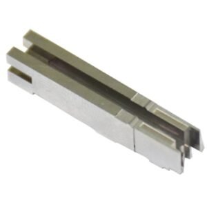


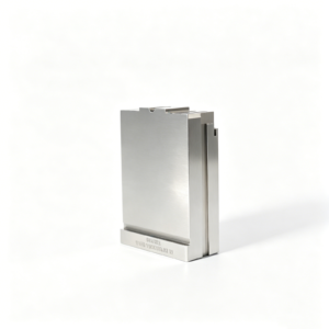


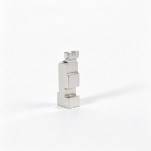
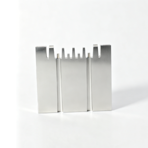
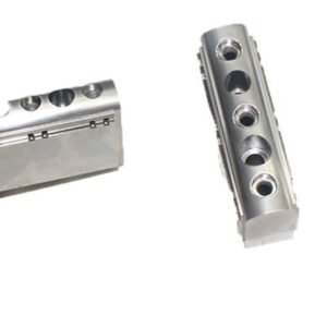
Why Engineering Teams Choose SUUXIANG for CNC Machined Valve Bodies
A disciplined workflow connects design intent to practical machining, inspection, and controlled delivery.
Drawing-First DFM Review
Review critical dimensions, datums, machining access, internal passages, and surface requirements before quotation assumptions become production commitments.
Critical Feature Focus
Identify bores, threads, sealing interfaces, and alignment features that require clear tolerance priorities and suitable inspection methods.
Process-Routed Planning
Plan CNC machining, EDM, grinding, fitting, and finishing around geometry, material condition, access constraints, and functional requirements.
Inspection Plan Alignment
Define measurement priorities, reporting needs, and acceptance criteria against the drawing so verification follows the agreed project requirements.
Controlled Revision Handling
Keep drawing revisions, manufacturing changes, and delivery information visible to reduce ambiguity across engineering, quality, and procurement teams.
Technical Communication
Discuss material, heat treatment, quantity, delivery targets, and mating context early to support clearer RFQs and responsible manufacturing decisions.
CNC Valve Bodies and Precision Component Families
Drawing-driven process routes for valve-body work, tooling components, connector molds, die parts and custom machined requirements.

CNC Machining Services
Precision CNC machining services for drawing-based valve bodies, mold components and custom parts. Reviews focus on material, datums, critical dimensions, tool access and inspection requirements before a process route is proposed.
Upload a Drawing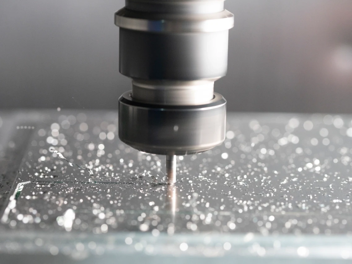
CNC Milling
Custom CNC milling services support prismatic parts, pockets, ports, mounting faces and complex mold features. Toolpath planning considers fixture strategy, cutter access, wall rigidity, machining allowance and the dimensions that require inspection.
Upload a Drawing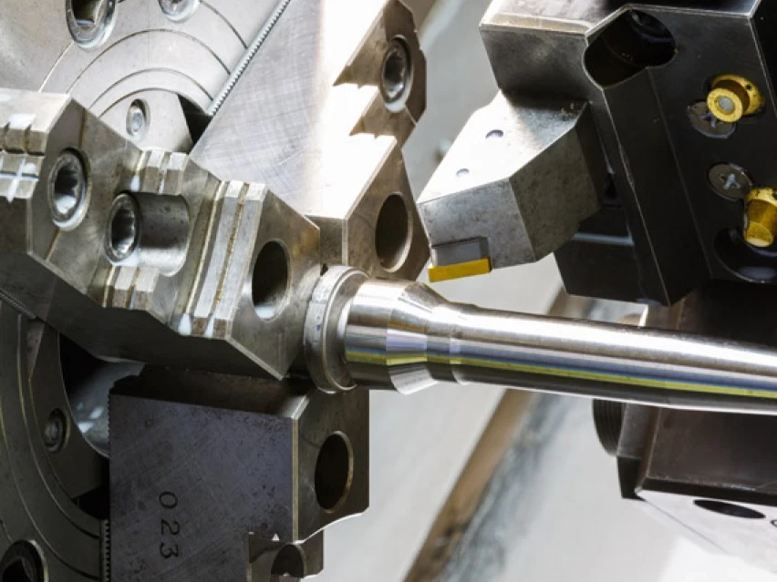
CNC Turning
Precision CNC turning services produce rotational features such as valve bores, threaded interfaces, shafts, bushings and locating diameters. Quotations should identify concentricity, runout, surface requirements, material condition and any secondary milling or grinding operations.
Upload a Drawing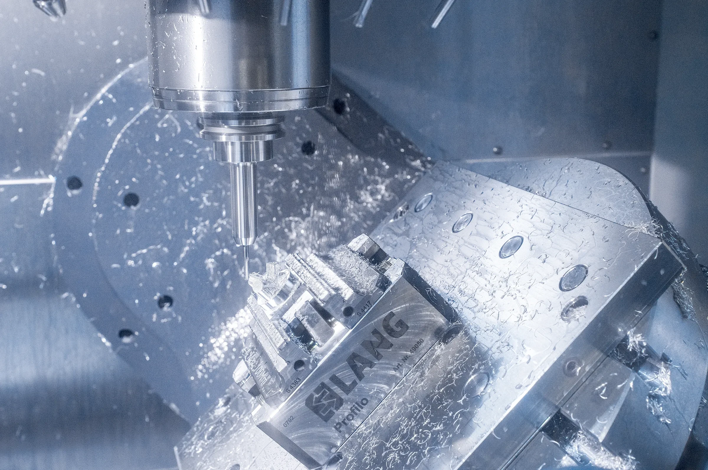
5-Axis Machining
5-axis CNC machining supports multi-face features, angled ports, compound surfaces and mold details where fewer setups can protect datum relationships. Feasibility depends on tool access, part clamping, feature depth, tolerance priorities and inspection strategy.
Upload a Drawing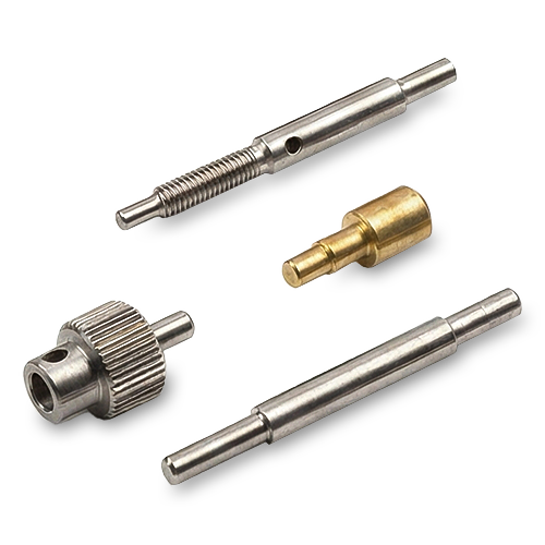
Swiss & Micro Machining
Swiss machining and micro machining support small, slender or intricate turned components with critical diameters and fine features. Drawing review should address stock form, length-to-diameter ratio, burr control, handling, measurement method and quantity.
Upload a Drawing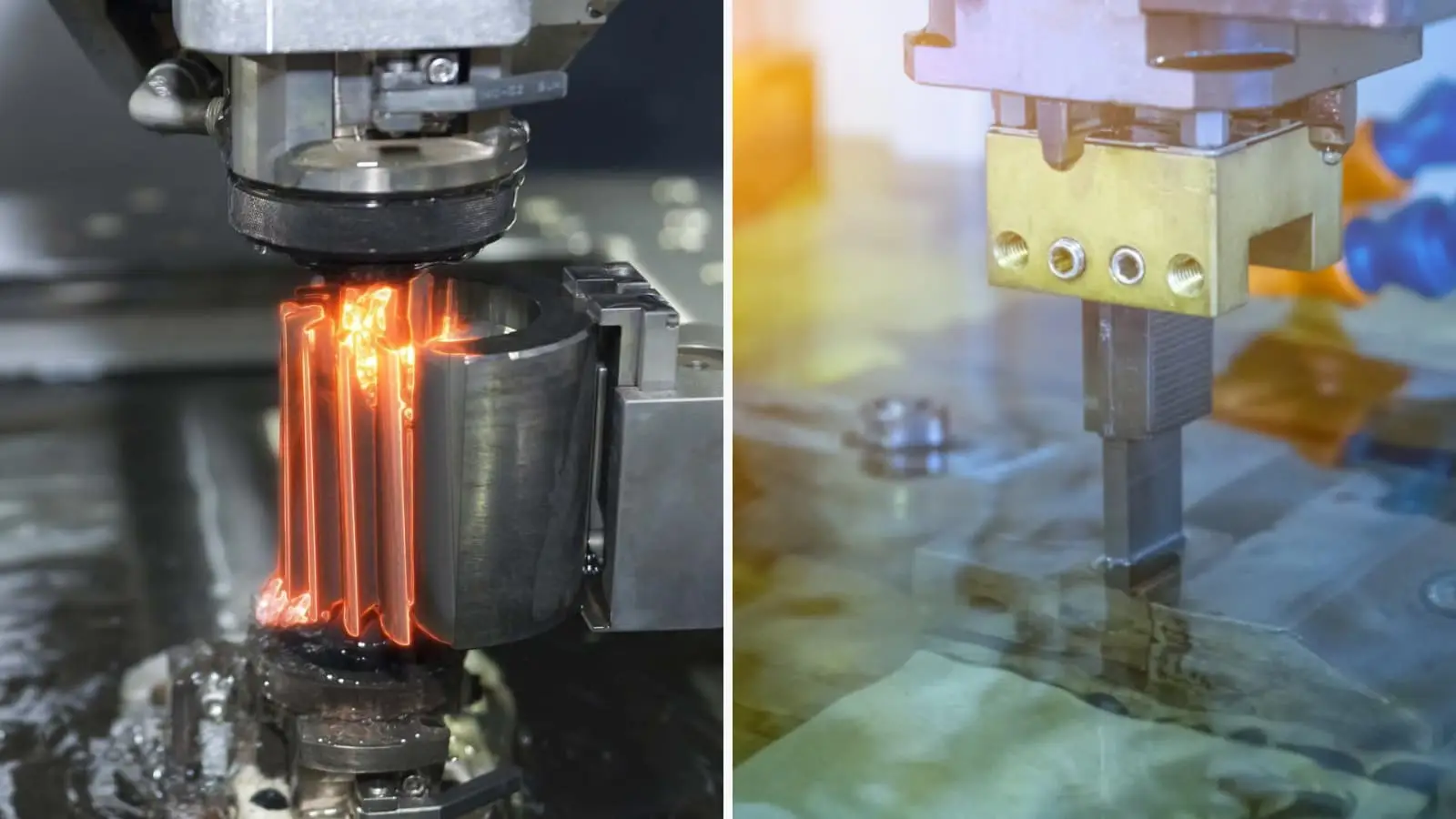
Wire & Sinker EDM
Wire EDM and sinker EDM services address hardened materials, narrow slots, internal corners, deep ribs and profiles beyond practical cutter access. Electrode strategy, wire path, finish requirements, recast-layer expectations and downstream fitting must be defined.
Upload a Drawing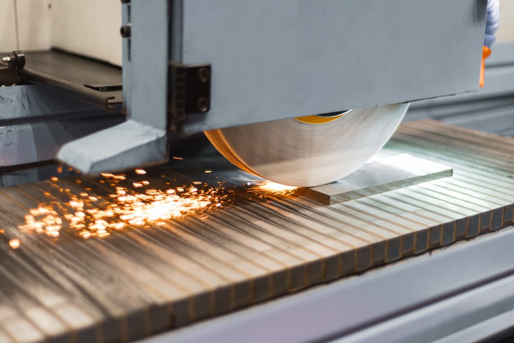
Precision Grinding
Precision surface and profile grinding establishes controlled flatness, parallelism, profiles and critical mating dimensions. The production route should reserve adequate grinding stock after heat treatment and define datum references, surface finish and inspection method.
Upload a Drawing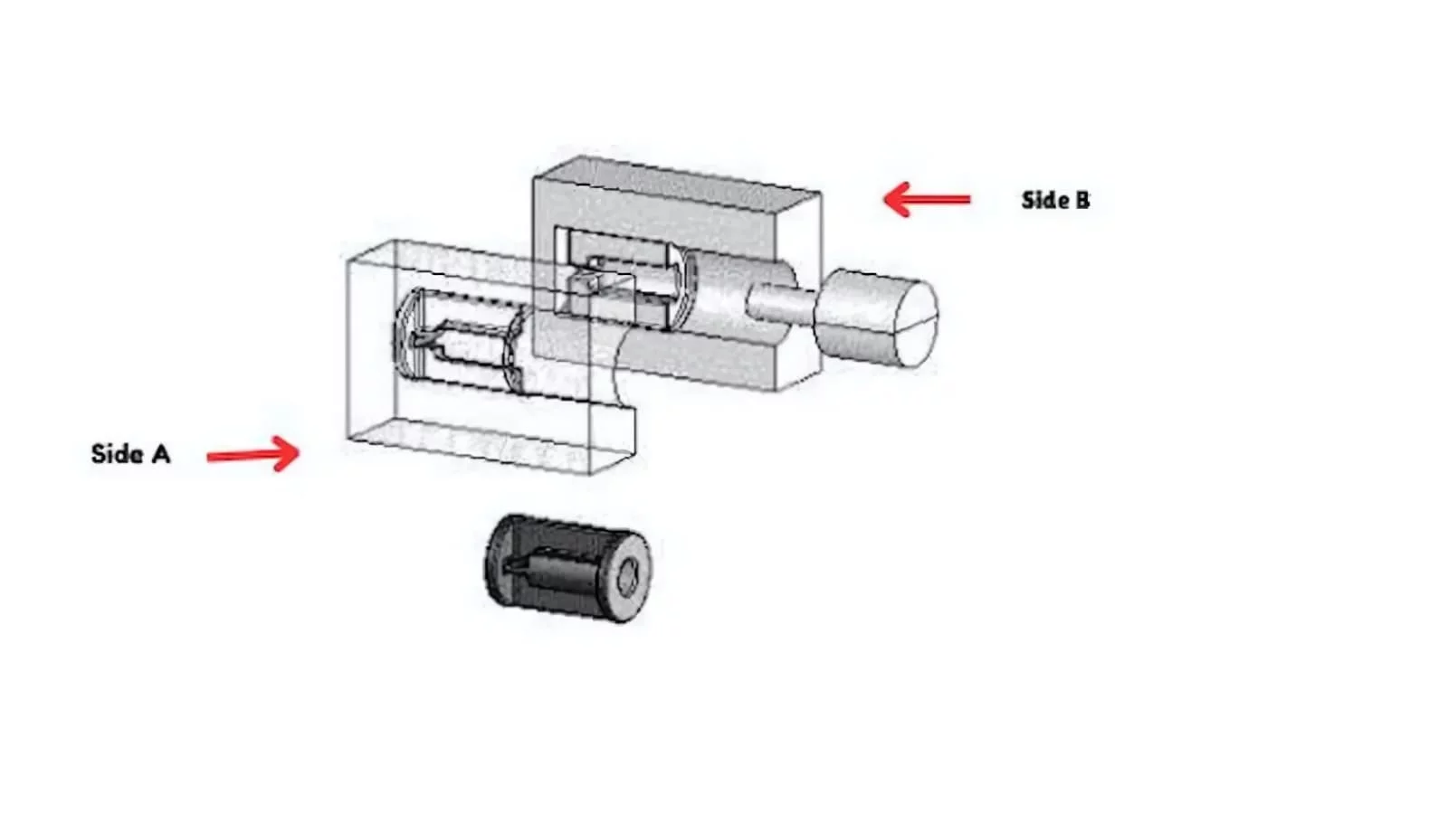
Mold Core & Cavity Inserts
Precision mold core and cavity inserts are made from customer drawings and specifications for molding tools. Review covers steel grade, heat treatment, cooling or vent features, EDM details, shutoff conditions, polishing requirements and critical interfaces.
Upload a Drawing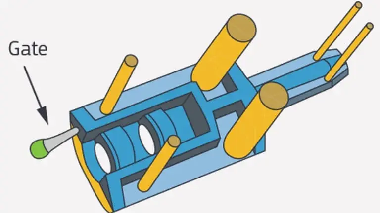
Ejector & Ejection Components
Ejector pins, sleeves and ejection components are produced for guided, repeatable mold movement. Buyers should specify diameters, fit classes, hardness, surface condition, head geometry, lubrication needs and mating-component requirements.
Upload a Drawing
Core Pins, Guide & Locating Components
Core pins, guide pins and locating components control cavity features, alignment and repeatability in mold assemblies. Requirements should identify datum relationships, engagement lengths, wear surfaces, material and heat-treatment condition, fit, and replacement interchangeability.
Upload a Drawing
Slides, Lifters, Gates & Mold Accessories
Mold slides, lifters, gates and accessories are configurable components for part release, side actions and controlled material flow. Manufacture depends on travel geometry, shutoff faces, wear provisions, tolerance stack, fitting needs and assembly interfaces.
Upload a Drawing
Connector Mold Components
Precision connector mold components support fine-pitch cavities, terminals, inserts and alignment features used in connector tooling. Drawing review addresses micro-feature access, pin geometry, EDM needs, wear surfaces, datum control and inspection of critical pitches.
Upload a Drawing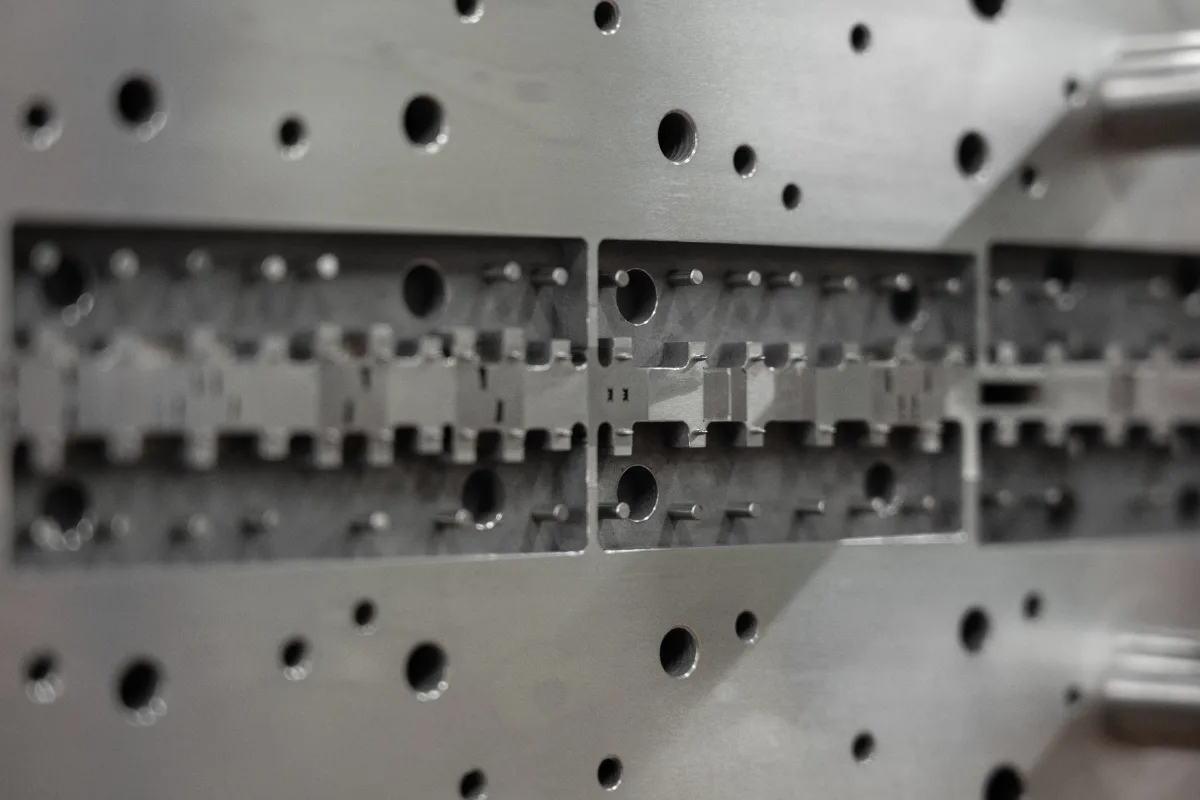
Stamping Die Components
Precision stamping die components support cutting, forming, guiding and locating functions in die assemblies. Process planning considers tool steel, heat treatment, clearance-critical edges, grinding stock, EDM features, fitting interfaces and dimensional verification.
Upload a Drawing
Injection, MIM, CIM & Overmolding Tooling
Injection, MIM, CIM and overmolding tooling components are evaluated within verified production scope. A drawing package should clarify molded material, shrinkage assumptions, inserts, gate or vent needs, critical interfaces, tool steel and expected inspection evidence.
Upload a Drawing
Machining Materials
CNC machining materials are selected against function, machinability, corrosion exposure, strength, hardness and finishing requirements. Submit the specified grade, material standard, condition and any traceability requirement so the process route can be assessed accurately.
Upload a Drawing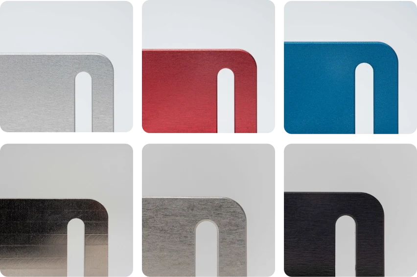
Surface Finishes & Heat Treatment
Surface finishing and heat treatment are planned around functional surfaces, hardness, corrosion resistance, wear, coating thickness and post-treatment distortion. Requirements should state the applicable specification, surface areas, masking needs and any final-grinding allowance.
Upload a Drawing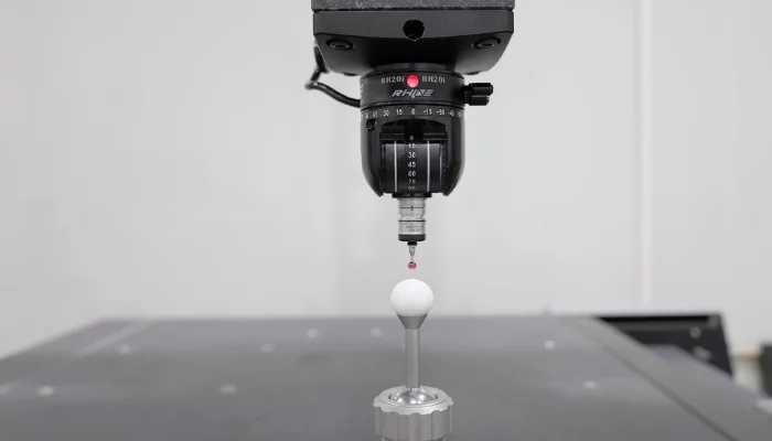
Quality, Metrology & Documentation
Precision inspection, metrology and quality documentation are aligned to the drawing and agreed inspection plan. Define critical dimensions, datums, reporting format, sampling expectations, material records, revision level and any customer-specific traceability requirements.
Upload a Drawing
Prototyping & Low-Volume Production
Rapid prototyping and low-volume manufacturing support controlled learning before broader production commitments. Provide drawings, quantities, material, critical features, application context, revision status, inspection needs and target delivery date for a practical review.
Upload a DrawingMaterials for CNC Machined Valve Bodies
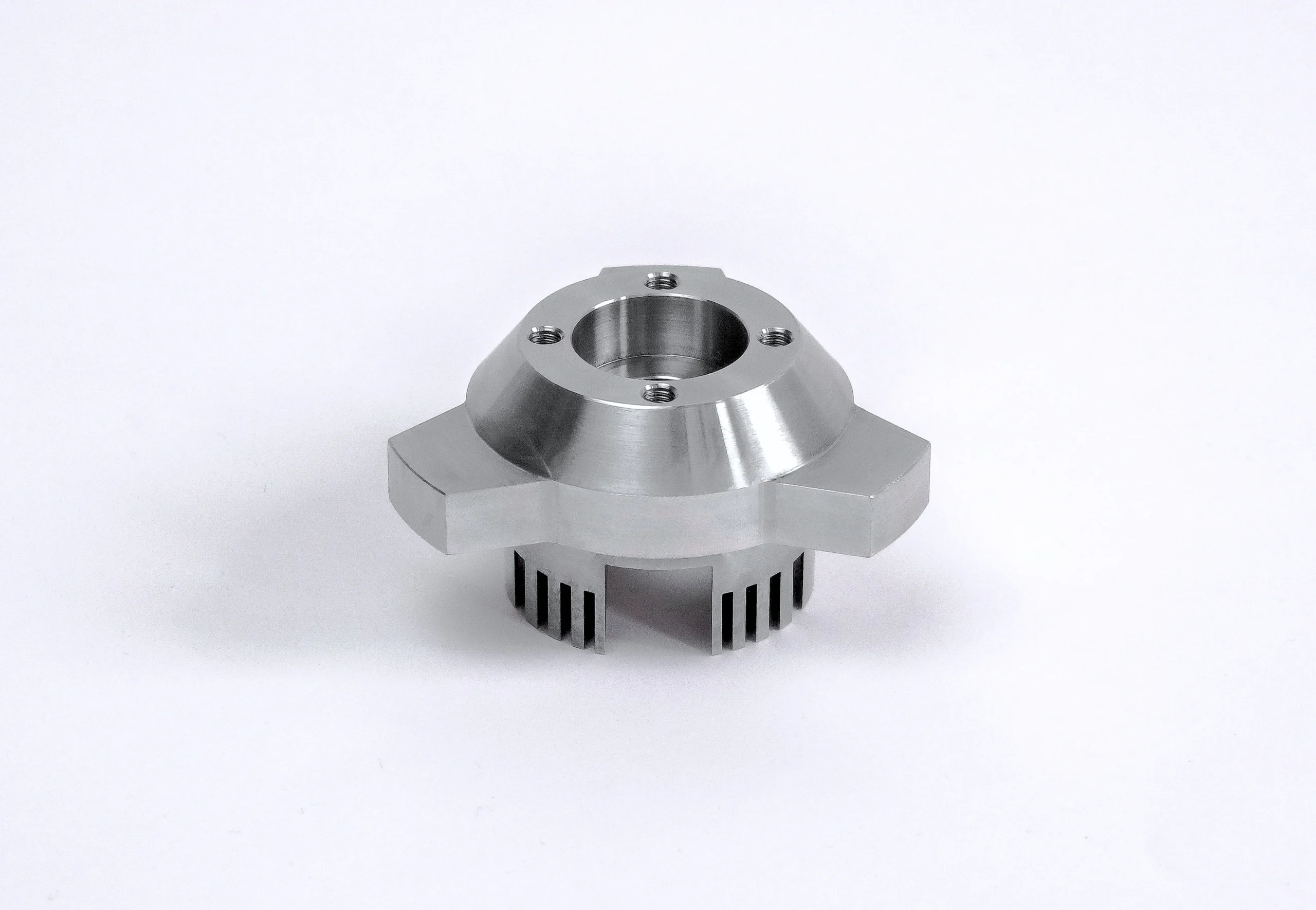
303 Stainless Steel
A practical option for valve bodies requiring corrosion resistance with comparatively efficient machining. It can suit ported housings and threaded features when the operating medium, sealing surfaces, and any post-machining finishing requirements are confirmed.
316L Stainless Steel
Considered where corrosion exposure or clean-media service drives material selection. Its machining response, sealing-face requirements, and heat or surface condition should be reviewed against the drawing, service environment, and inspection plan before production.
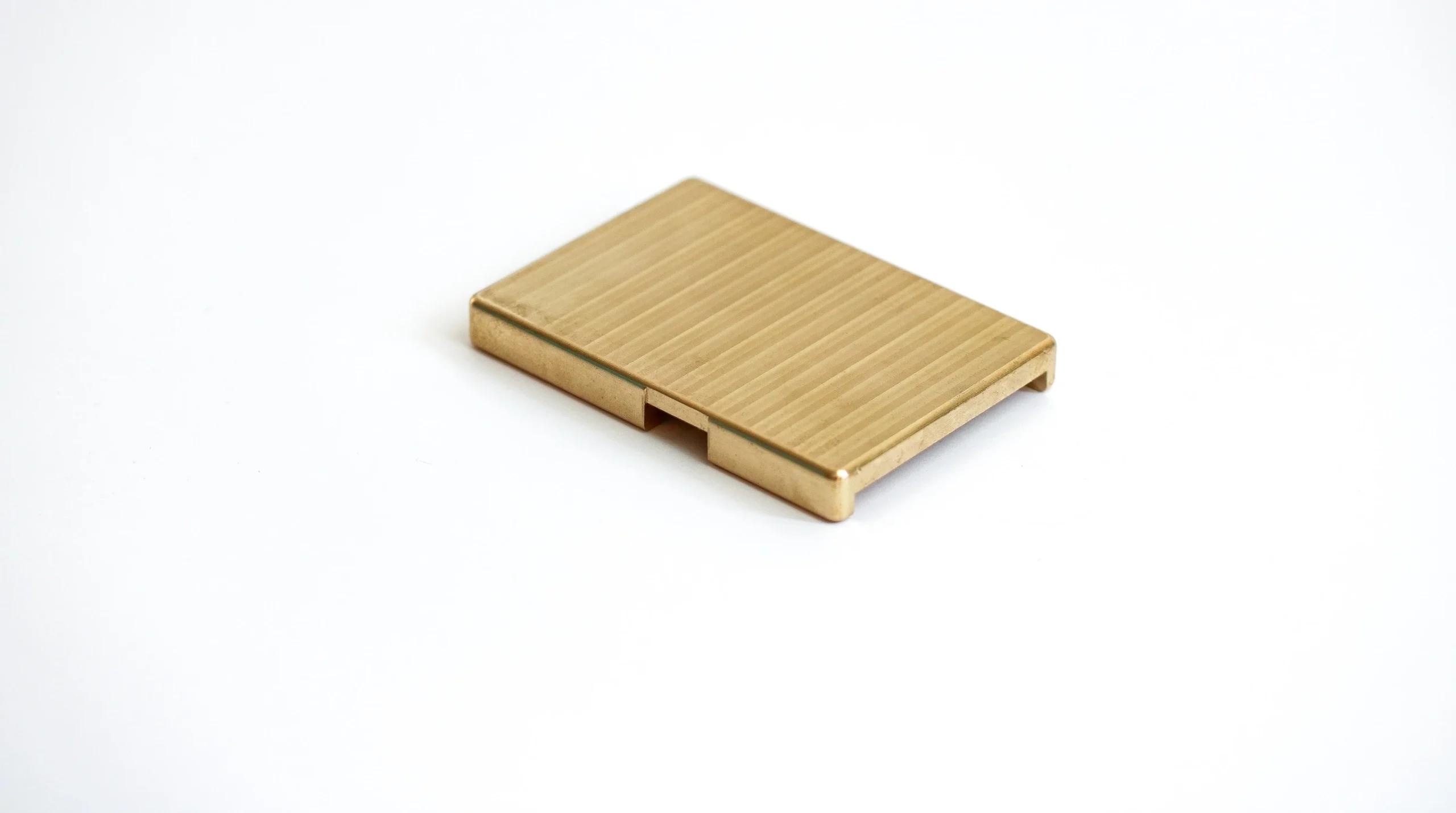
Brass Alloys
Often evaluated for compact valve and fitting bodies where machinability, thread quality, and fluid compatibility matter. Grade selection should account for pressure, medium, mating materials, thread specification, burr-control access, and any applicable compliance requirements.
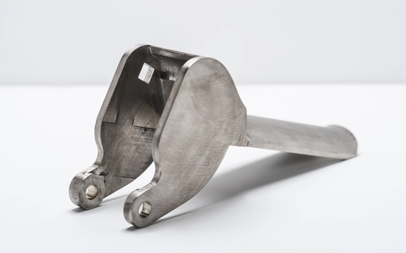
Alloy Steel
A candidate for valve-service parts where strength, wear behavior, or pressure-related design requirements influence the process route. SUUXIANG reviews heat-treatment sequence, machining allowance, bore finishing, corrosion protection, and critical dimensions from the drawing.
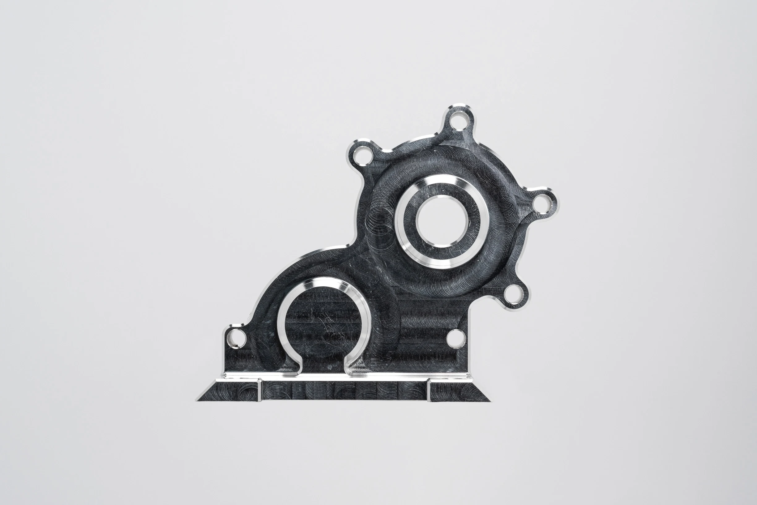
Aluminum Alloys
Useful when lower component mass and good machinability support the application. Alloy grade, coating need, corrosion exposure, threaded-port loading, sealing interface, and compatibility with the specified fluid should be resolved during DFM review.
CNC Machined Valve Bodies: Available Process Routes
CNC Milling
CNC milling creates port faces, external profiles, mounting features and accessible fluid passages. Tool access, datum location and burr-control requirements are reviewed so functional geometry can be machined and inspected against the drawing.
CNC Turning
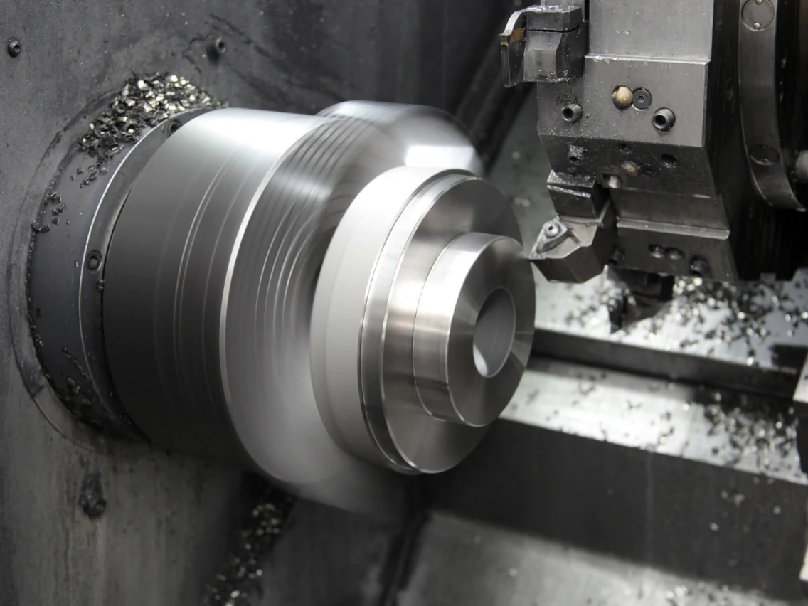
CNC turning supports rotational valve-body features such as outer diameters, threaded sections, counterbores and concentric faces. The process route considers clamping, runout, material condition and the relationship between turned features and later machining.
Wire EDM
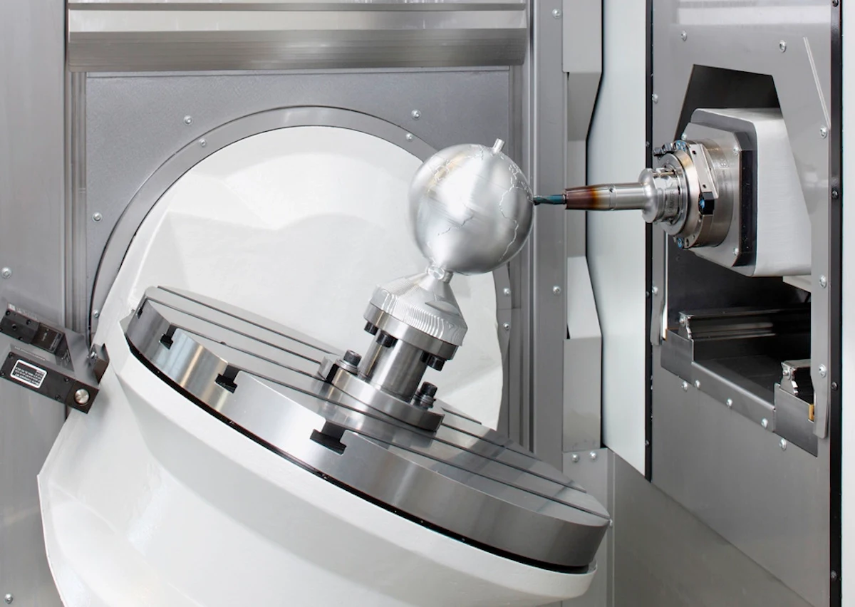
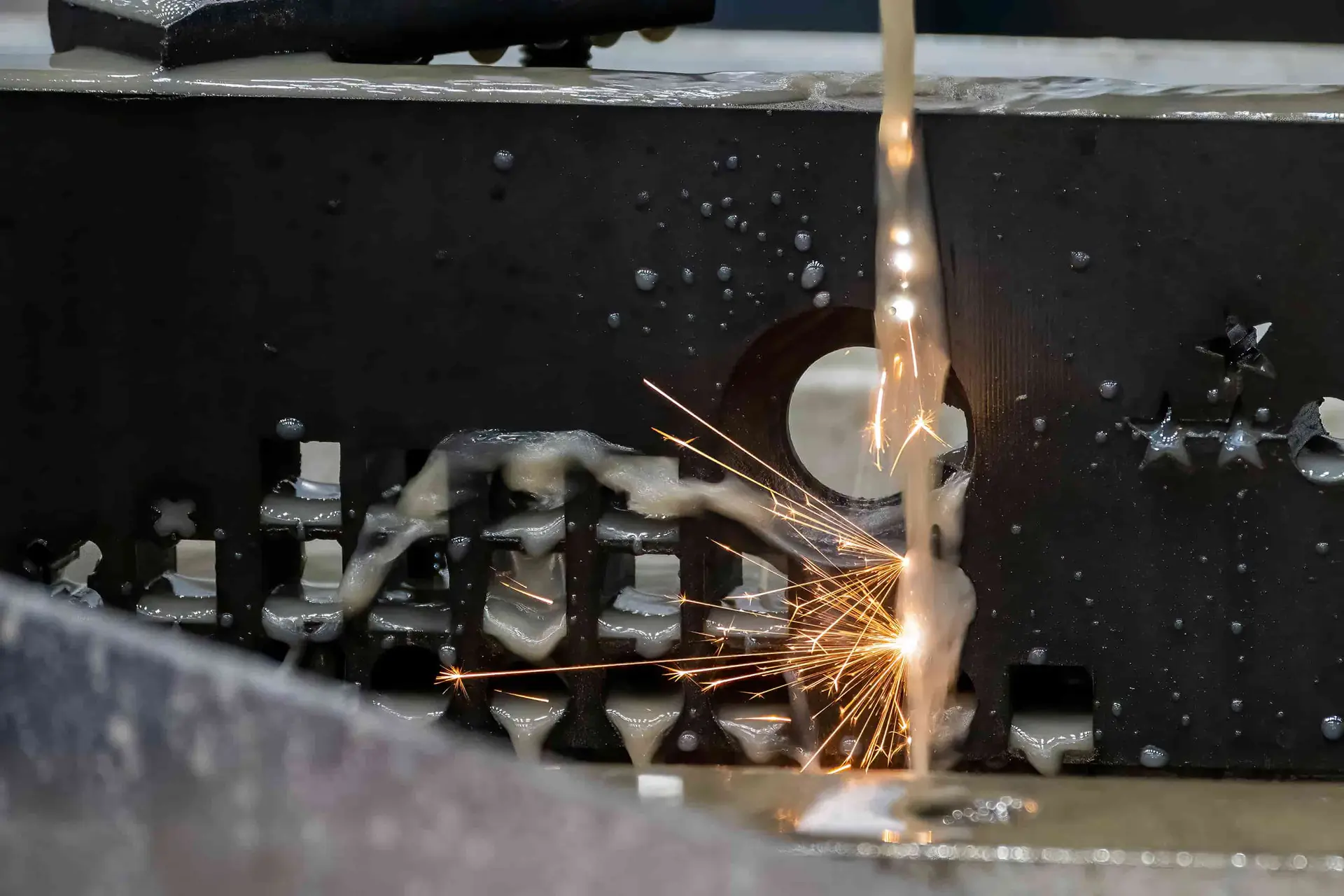
Wire EDM is considered for precise through profiles, narrow slots and difficult-to-machine details where a wire path is appropriate. The review addresses start-hole access, corner conditions, stock allowance and the required relationship to critical datums.
Sinker EDM
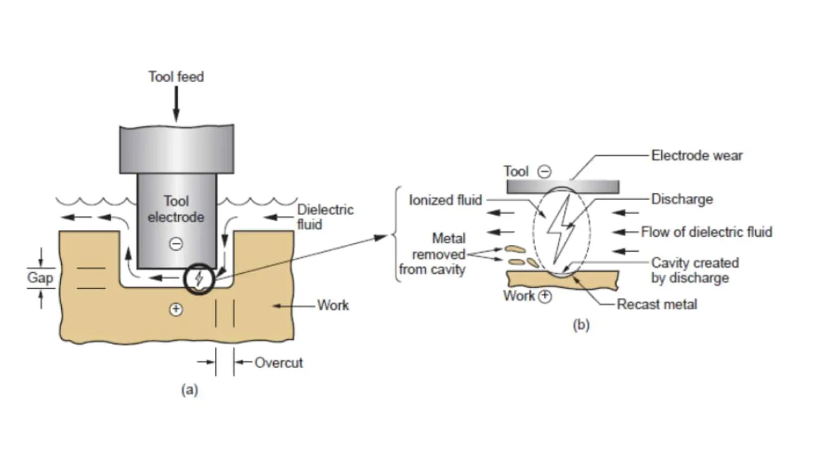
Sinker EDM may be selected for internal forms, sharp detail or areas with limited conventional-tool access. Electrode strategy, burn allowance, surface requirements and subsequent finishing needs are defined through drawing-led process planning.

Precision Grinding
Precision grinding finishes applicable faces, diameters and datum-related features after machining or heat treatment. Grinding stock, distortion risk, surface requirements and the inspection method should be agreed before the final route is confirmed.
CNC Machined Valve Bodies: Functional Features and Applied Components
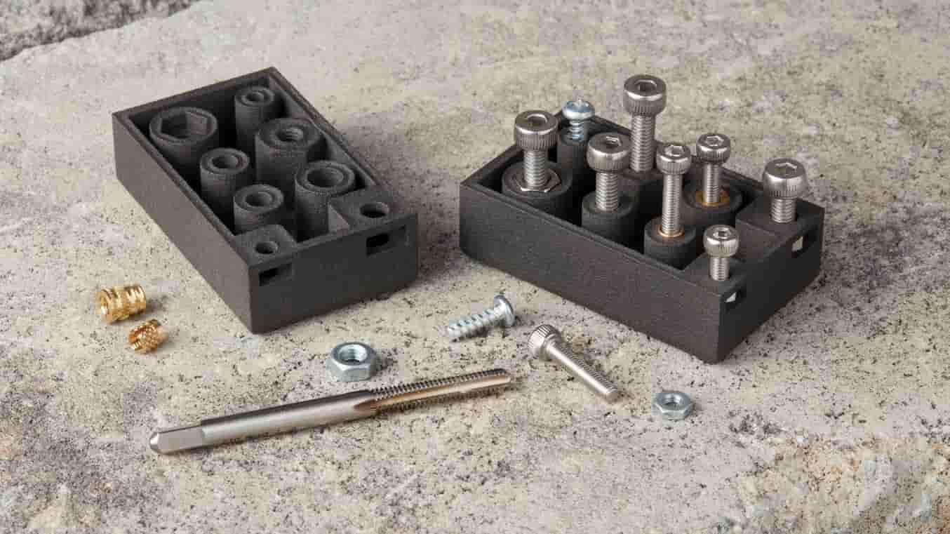
Threaded Ports
Threaded ports connect CNC machined valve bodies to mating fittings, covers, or sensors. Provide the thread standard, engagement requirements, sealing method, and access constraints for drawing review and process planning.

Sealing Interfaces
Seats, O-ring glands, gasket faces, and sealing bores require defined geometry and surface priorities. Identify the mating component, pressure medium, and critical dimensions so the appropriate machining and inspection approach can be evaluated.
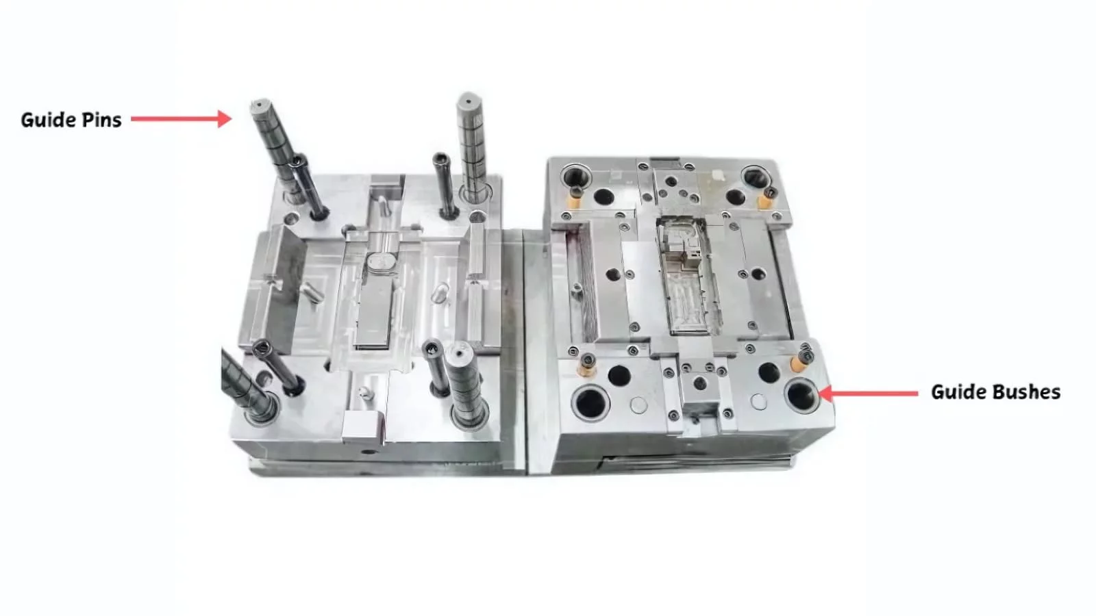
Locating Features
Dowel holes, datum faces, pilot diameters, and locating shoulders help control orientation during assembly. Their relationship to functional bores and mounting patterns should be dimensioned clearly to support fixture planning and verification.

Plugs and Inserts
Threaded plugs, press-fit inserts, and replaceable seats may close passages or add a durable functional interface. Share material, retention, sealing, and service requirements so compatibility and machining sequence can be reviewed.
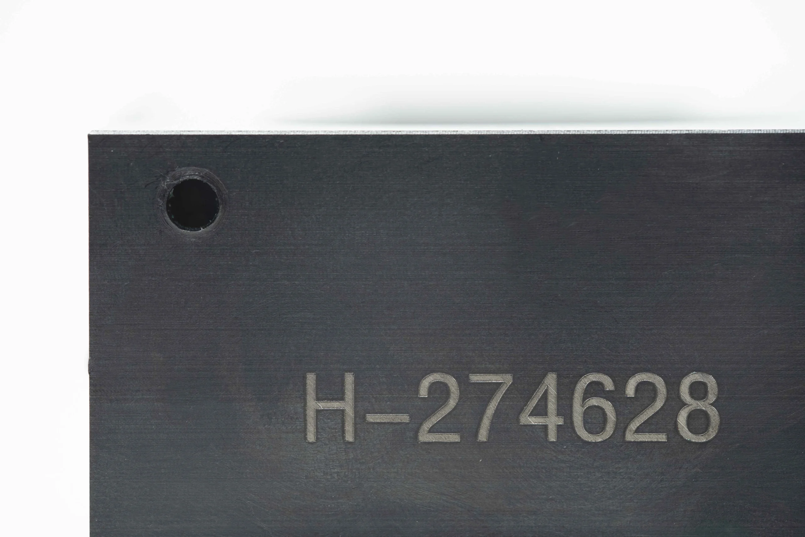
Identification Elements
Part numbers, revision marks, orientation indicators, and traceability details can be added where practical. Define the marking method, location, character requirements, and any surface-finish restrictions within the drawing package.
About SUUXIANG
SUUXIANG is the sole public-facing brand of Dongguan SuuXiang Precision Mold Co., Ltd., established in 2010 and based on the 2nd Floor of Sanhe Industrial Park, Chang’an Town, Dongguan, Guangdong, China. XiaoCheng Huang is the founder and legal representative. We help international engineering and sourcing teams translate specifications into inspected CNC parts, precision mold components, connector tooling, and die components.
For cnc machined valve bodies and other custom work, we plan the route around the drawing rather than a generic process claim. CNC milling and turning, multi-axis machining, EDM, precision grinding, fitting, and inspection are coordinated according to critical dimensions, datum strategy, machining access, material requirements, and surface priorities.
What distinguishes SUUXIANG is a practical engineering workflow before production commitments. We review DFM risks, tolerance stack, internal-feature access, finishing allowances, inspection needs, and revision status with the customer, then keep manufacturing and delivery information traceable to the agreed order requirements.

Critical Capabilities for CNC Machined Valve Bodies
Drawing-Led DFM Review
SUUXIANG reviews the drawing, 3D model, material, application, quantity, and quality expectations before quoting CNC machined valve bodies. The discussion identifies critical dimensions, datum relationships, tool access, sealing-feature priorities, and risks that should be resolved before production commitments.
- Confirm critical-to-quality dimensions and datum strategy
- Review port geometry, wall conditions, and tool approach
- Identify surface, thread, and mating-component requirements
- Align drawing revisions before process planning

Access and Feature Planning
Cross-drilled passages, deep bores, threaded ports, and intersecting features require a defined machining sequence. SUUXIANG plans CNC milling, turning, and multi-axis operations around clamping stability, reference surfaces, internal-access limitations, and practical deburring requirements for the supplied design.
- Establish stable locating and clamping surfaces
- Sequence operations around accessible datums
- Review intersections for burr-removal access
- Flag geometry that may require design clarification

EDM and Grinding Strategy
Where conventional cutting cannot reliably reach a feature or finish a functional surface, the process route may incorporate wire EDM, sinker EDM, or precision grinding. The selected method should follow the drawing’s geometry, material condition, machining allowance, and inspection priorities rather than a default process.
- Assess wire paths and electrode access early
- Plan heat treatment and finish-machining sequence
- Maintain appropriate stock for grinding operations
- Match the process route to critical functional features
Inspection and Revision Control
For CNC machined valve bodies, inspection planning starts with the features that affect assembly and function. SUUXIANG aligns the inspection method and required documentation with the order, while keeping revision information visible through manufacturing coordination and final verification.
- Define inspection points for critical dimensions
- Confirm reporting and traceability expectations
- Compare final parts against the approved revision
- Keep delivery requirements aligned with the inspection plan
CNC Machined Valve Bodies: Drawing-Based Sourcing Compared
Compare SUUXIANG’s review-led workflow with quotation-focused sourcing approaches before releasing a valve-body order.
← Swipe left or right to view →
Production Workflow for CNC Machined Valve Bodies
Each project follows a drawing-led sequence that aligns critical features, process choices, inspection evidence, and delivery requirements before shipment.
Review Drawings and Requirements
We review 2D drawings, models, material, quantity, application, critical dimensions, surface requirements, inspection needs, and requested delivery timing before quotation.
Plan the Process Route
DFM review establishes datum strategy, machining access, workholding, drilling sequence, EDM or grinding needs, heat-treatment order, and inspection approach for the part.
Machine Functional Features
CNC milling, turning, multi-axis machining, and related operations create external geometry, ports, bores, threads, and accessible flow-path features according to approved requirements.
Finish Critical Surfaces
Where the drawing requires it, EDM, precision grinding, deburring, and fitting address sealing surfaces, tight-feature access, controlled edges, and finishing allowances.
Inspect and Document Results
Inspection follows the agreed plan, focusing on critical dimensions, datums, surface requirements, and order-specific reporting or traceability documentation before release.
Coordinate Packing and Delivery
Released CNC machined valve bodies are packed for the part geometry and shipment requirements, with revision status and delivery coordination kept visible to the customer.
How to Source CNC Machined Valve Bodies
A controlled path from technical requirements to inspected parts and coordinated delivery.
Submit Your Technical Package
Provide the 2D drawing, 3D model when available, material, quantity, target date, inspection needs, and application details affecting ports, seals, threads, or mating components.
Review DFM and Quotation
SUUXIANG reviews critical dimensions, datums, machining access, process sequence, EDM or grinding needs, and inspection expectations before confirming a quotation and production approach.
Approve Production Details
Confirm the agreed drawing revision, material and heat-treatment requirements, quality plan, and any sample, first-article, or reporting requirements applicable to your order.
Coordinate Inspection and Delivery
Manufacturing follows the approved process route, with inspection documentation matched to the verified plan and delivery information kept visible through final shipment coordination.
Customer References: Publication Pending Verification
Customer Outcomes for CNC Machined Valve Bodies
Customer testimonial pending verification. This slot will document the approved drawing revision, inspection scope, quantity, delivery outcome, and the customer-approved result for a CNC machined valve body project.
Customer testimonial pending verification. This slot will capture a confirmed outcome related to bore alignment, port threads, sealing features, inspection reporting, or revision control after the customer authorizes publication.
Customer testimonial pending verification. This slot will summarize a documented sourcing or engineering result, including approved measurable outcomes only after the customer name, role, company, and project details are verified.
CNC Machined Valve Bodies FAQ
Practical answers for engineering and procurement teams preparing a drawing-led valve-body RFQ.
What files should I send for cnc machined valve bodies?
Can SUUXIANG quote low-volume cnc machined valve bodies?
How do you plan lead time for cnc machined valve bodies?
Which materials can be considered for a custom valve body?
What inspection documents can I request with an RFQ?
Can you provide samples before a production order?
How are drawing revisions controlled for valve body machining?
Can SUUXIANG ship internationally and protect project information?
The Complete Buyer’s Guide to cnc machined valve bodies
Use this drawing-led framework to select materials, define critical features, compare qualified suppliers, control total cost, and avoid specification gaps that cause leaks, rework, delayed launches, or unreliable valve performance.
1. What Are cnc machined valve bodies?
One valve body is the primary pressure-containing housing that routes liquid or gas between ports while locating functional elements such as a ball, spool, poppet, seat, and seals. Its geometry establishes the flow path and the interfaces through which the valve connects to the surrounding system.
Two or more intersecting passages commonly make cnc machined valve bodies drawing-led parts rather than generic turned components. CNC milling, turning, boring, and thread machining are selected against the drawing’s datums to control bore relationships, port location, thread engagement, sealing faces, and accessible internal transitions.
Three application groups illustrate the purchasing focus: hydraulic and pneumatic controls, process-fluid equipment, and thermal-management or gas-handling assemblies. Buyers should define the operating medium and pressure, mating thread or fitting standard, critical bore and seat requirements, surface finish, cleanliness and deburring expectations, inspection method, and revision-controlled drawing before production review.
2. Evolution of Valve Body Manufacturing
Two historical routes still shape valve-body sourcing: cast-first production for near-net external form and conventional setups for drilled, bored, and threaded features. Both can suit stable designs, but repeated repositioning makes datum transfer, port alignment, and change control more dependent on fixtures and operator discipline.
CNC turning and milling shifted more geometry into programmed, repeatable operations. Multi-axis machining can reach several faces from fewer setups, while controlled drilling, boring, interpolation, and thread machining make complex porting practical when tool access, chip evacuation, and internal deburring are reviewed before release.
Digital inspection changed the buyer’s evidence package as much as the cutting process. A drawing-led plan can link critical dimensions to defined datums, measurement methods, revision status, and inspection records; this supports prototype iteration and lower-volume orders without treating every change as a new dedicated-tooling program.
SUUXIANG begins this decision with the drawing, model, material, quantity, application, and quality requirements. The appropriate route may combine CNC machining with EDM, grinding, fitting, and inspection when the verified project scope requires it.
3. Types of cnc machined valve bodies
Seven common architectures differ mainly by closure element, flow-path direction, and whether the body is serviceable as a replaceable insert. Select the body only after pressure, actuation, port standard, sealing method, and assembly access are defined.
| Body Type | Operating Principle | Typical Use | Key Machining Challenge |
|---|---|---|---|
| Ball | Rotating bore opens or blocks flow | Fast isolation | Seat and port alignment |
| Spool | Sliding lands meter connected ports | Directional hydraulic control | Bore straightness and land fit |
| Poppet | Axial element closes on a seat | Check or pressure control | Seat concentricity |
| Needle | Tapered tip meters a small orifice | Fine flow adjustment | Tip-to-seat geometry |
| Cartridge | Replaceable insert fits a cavity | Serviceable circuits | Cavity and thread control |
| Manifold | Cross-drilled passages route circuits | Compact multi-valve systems | Intersection deburring |
| Fitting-Integrated | Valve and connector share one body | Space-limited assemblies | Thread sealing and tool access |
Rotary And Linear Closure Bodies
Ball bodies rotate a drilled sphere through quarter-turn actuation; spool, poppet, and needle bodies use linear travel. Their guide bore, seat concentricity, and actuator alignment govern sealing and response.
Cartridge, Manifold, And Fitting Bodies
Cartridge bodies retain a standardized valve insert, while manifold bodies distribute fluid through intersecting drilled passages. Fitting-integrated bodies combine connection geometry and valve function, reducing joints but tightening thread, wrench-clearance, and deburring requirements.
Architecture Comparison
Two-port isolation favors simple flow paths; multi-port control favors spool or manifold layouts. Confirm service access and internal-cleanliness requirements during drawing review.
4. Materials for cnc machined valve bodies
6061-T6, brass, stainless, and steel each shift the balance among mass, corrosion, pressure margin, and machining cost. For cnc machined valve bodies, choose from operating conditions—not availability.
| Material | Primary Advantage | Key Watchpoint | Cost Direction |
|---|---|---|---|
| Aluminum alloys | Low weight; good machinability | Galvanic and media compatibility | Low to medium |
| Brass | Fast machining; corrosion resistance | Pressure and dezincification review | Medium |
| Stainless steels | Corrosion resistance | Higher cutting effort | Medium to high |
| Carbon/alloy steels | Strength for demanding duty | Corrosion protection | Medium |
| Specialty alloys | Application-specific performance | Availability and machining cost | High |
Match Metal To Service
316/316L stainless suits many corrosive or clean-fluid duties; carbon or alloy steel is often selected where pressure-driven strength dominates. Confirm the exact medium, contaminants, temperature, and pressure cycle before release.
Protect Interfaces And Surfaces
Aluminum reduces weight but demands review of coolant chemistry and galvanic contact with dissimilar metals. Anodizing, passivation, plating, or coating must be compatible with the medium, threads, seals, and dimensional requirements.
Validate The Final Specification
Final material selection must be validated against the specified fluid, pressure, temperature, seals, and applicable standards. Provide grade, temper or heat treatment, finish, mating materials, and any traceability requirement in the drawing package.
5. Custom Features for Valve Bodies
A 2D drawing should identify every pressure boundary, datum, and mating interface before machining begins. For cnc machined valve bodies, customization is valuable when it improves sealing, flow routing, assembly, or service access.
| Feature | Drawing Requirement | Integration Risk |
|---|---|---|
| Threaded port | Standard and gage | Reduced with confirmed interface |
| O-ring gland | Groove and finish | Leakage if unspecified |
| Cross-drilled passage | Deburring access | May need extra inspection |
Define Functional Interfaces
Three interface groups deserve explicit callouts: port layout, thread form, and seal geometry. Specify NPT, BSPP, or SAE/ORB only when the mating standard, size, gage method, and sealing method are confirmed.
Two sealing features—O-ring glands and flange faces—need groove dimensions, finish requirements, and datum relationships. Seat geometry must also identify the mating element and the functional surface.
Review Complex Internal Features
Cross-drilled passages require a defined intersection, deburring approach, and cleanliness expectation. Unique flow paths, deep bores, thin walls, or inaccessible seats may require DFM review, special tooling, EDM, or added inspection.
One mounting pattern should include hole type, positional tolerance, and the datum scheme used at assembly. Assembly-ready features can include counterbores, locating bores, wrench flats, and controlled edge breaks.
Separate Finish From Function
Two finish categories should remain separate on the drawing. Functional requirements cover sealing faces, bore finish, corrosion exposure, and coating compatibility; cosmetic requirements cover visible texture, color, and markings.
One marking note should state method, content, location, and whether it may affect a pressure boundary. SUUXIANG can review these requirements against the submitted drawing and inspection plan.
6. Quality Elements in cnc machined valve bodies
Critical-to-quality features should be individually toleranced and inspected on the drawing; general tolerances do not define leak-tight performance. For cnc machined valve bodies, acceptance criteria must connect each functional feature to a datum, method, and record.
Bores And Seats
Bore axis position, diameter, roundness, and cylindricity should reference functional datums. Seat angle or profile, concentricity, and surface finish require explicit limits because the mating seal responds to geometry, not nominal size alone.
Ports And Threads
Thread designation must state the exact form, class, depth, and sealing expectation. Specify the applicable go/no-go or functional gauge, port-location tolerances, and sealing-face flatness relative to assembly datums.
Internal Cleanliness And Testing
Cross-drilled intersections need a defined burr condition and cleaning requirement, including any prohibited loose particles. Material certificates, heat-treatment records where required, and revision identity should remain traceable to the order.
Pressure or leak testing must state medium, pressure, hold time, allowable leakage, test temperature if relevant, and reporting format. SUUXIANG can review these requirements against the drawing and verified inspection plan before production.
7. How to Choose a Valve Body Manufacturer
Before RFQ award, evaluate the supplier’s control plan against the drawing’s functional risks. For cnc machined valve bodies, a credible answer connects each requirement to a process, verification method, and revision record.
| Evaluation Area | Question Before Award | Expected Evidence |
|---|---|---|
| DFM | Are risks resolved? | Marked drawing |
| Inspection | How are CTQs verified? | Inspection plan |
| Production | How are changes controlled? | Revision record |
Review The Drawing Response
100% of quoted critical features should be identified against datums, not merely repeated from the print. Ask how the supplier will access bores, cross-drill passages, control burrs, and sequence machining after heat treatment.
- Request written DFM exceptions
- Confirm fixture and datum strategy
- Ask for prototype review timing
Verify Functional Features
Each port thread, seat, and O-ring groove needs a stated inspection method and acceptance criterion. Ask whether calibrated thread gauges, dimensional reports, visual internal-passage checks, and specified pressure or leak tests are available when required.
- Name thread standard and gauge
- Define sealing-surface finish
- Specify test medium and pressure
Control Production Changes
One approved prototype does not automatically control later lots. Require material traceability, first-article evidence, revision-controlled programs, and notification before substitutions, route changes, or inspection-plan changes.
- Match material certificate to order
- Approve first article before release
- Define change-notification process
8. Common Buyer Mistakes to Avoid
Eight recurring RFQ gaps can turn a dimensionally acceptable valve body into a leaking, contaminated, or non-mating assembly. Address them before quoting and convert each requirement into an inspection-plan checkpoint.
Complete Drawing Package
2D drawings without datum references, critical dimensions, or revision status invite inconsistent interpretation. Submit the released drawing, 3D model, tolerance scheme, and a marked CTQ list.
1 overlooked mating interface can make correct individual dimensions fail at assembly. Include fitting, seal, spool, and adjacent-component drawings or controlled interface dimensions.
Seals And Threads
3 missing sealing details—seat geometry, O-ring gland standard, and finish—leave leak performance undefined. State seal type, groove standard, required Ra, and permitted damage criteria.
4 thread callouts that omit standard, class, gauge method, or sealant intent can cause incompatible ports. Specify the complete thread designation and the mating fitting.
Cleanliness And Material
2 cross-drilled passages can retain burrs and chips that obstruct flow or damage seals. Define deburring access, cleanliness limit, rinse method, and inspection evidence.
1 lowest-cost alloy may fail corrosion, pressure, media, or galvanic requirements. Name the material grade, condition, heat treatment, coating, and operating medium.
Testing And Approval
2 test variables—medium and pressure—cannot be inferred from service intent. Put proof pressure, leak limit, test medium, dwell time, and record format in the quality plan.
1 first article proves only the sampled build, not ongoing process control. Define first-article acceptance separately from production approval, sampling, revision control, and release criteria.
9. From Drawing to Production Launch
A controlled launch for cnc machined valve bodies begins before a purchase order: the supplier needs a confidential, revision-identified drawing package and the application context behind it. Each approval gate should assign a clear owner and a recorded acceptance criterion.
Freeze The Technical Package
Revision A should include the 2D drawing, 3D model where available, material, heat treatment, critical datums, port-thread callouts, sealing requirements, quantity, and target date.
One application note should state the medium, pressure or leak-test requirement, mating parts, cleanliness expectation, and packaging constraints.
Close DFM And Quote Gaps
A written DFM response should identify tool access, intersecting-passage deburring, setup datum, inspection method, and any proposed process change before quotation acceptance.
One quote review should align price, lead time, included documentation, test responsibility, sampling, and delivery terms with the released revision.
Approve Before Production Release
First-article approval should compare measured results against the agreed drawing and inspection plan before a pilot build or production release.
Each shipment should carry the approved revision, quantity, packaging instruction, and required records; later changes require a new revision notice and documented disposition of work in process.
10. cnc machined valve bodies Pricing
1 drawing-specific quote starts with material grade, stock form, overall envelope, and estimated machine time; larger blanks and difficult-to-machine alloys increase both material use and cycle risk. Multi-face setups, tight bore or seat tolerances, and intersecting internal passages can add fixturing, tool changes, deburring, and inspection operations.
3 post-machining items commonly change the commercial scope: finishing, dimensional reporting, and pressure or leak testing. Define only functional surface finishes and CTQ features, state the test medium and acceptance criteria, and separate prototype urgency from the production schedule.
10, 50, and 250-piece quantities should be priced from the same released revision but not assumed to have the same unit cost. Higher volume can distribute programming and fixture effort, while SUUXIANG should confirm the applicable route, inspection plan, capacity, and delivery window against the current drawing.
| Quantity tier | Primary cost drivers | Lead-time influences | Buyer cost action |
|---|---|---|---|
| 1–10 | Programming, setups, material minimums | Engineering review; special tools | Supply complete 2D/3D data and CTQ datums |
| 11–100 | Cycle time, multi-face work, inspection | Fixture complexity; finishing queue | Standardize threads and reduce nonfunctional tolerances |
| 101+ | Fixture amortization, repeatability controls | Material availability; batch inspection | Freeze revision and forecast releases |
Upload Your CNC Machined Valve Bodies Drawing
Send your 2D drawing, 3D model, material, quantity, quality priorities, and target delivery date for a drawing-led DFM and quotation review.