
Custom CNC Machined Flanges, Reviewed Before Production
Send your drawing for custom CNC machined flanges with DFM, critical-dimension review, process planning, and inspection requirements aligned before manufacturing.
Representative Custom CNC Machined Flange Components
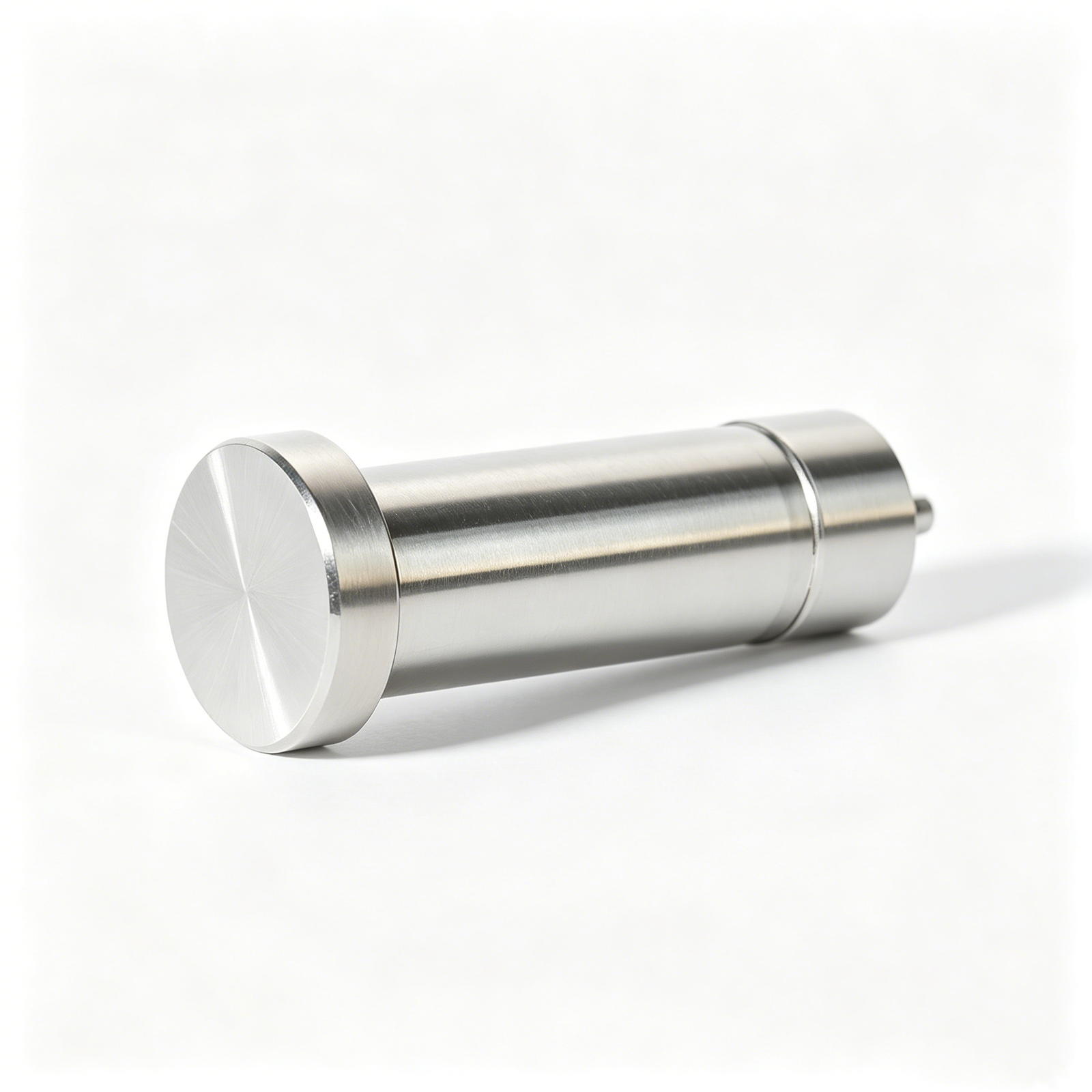

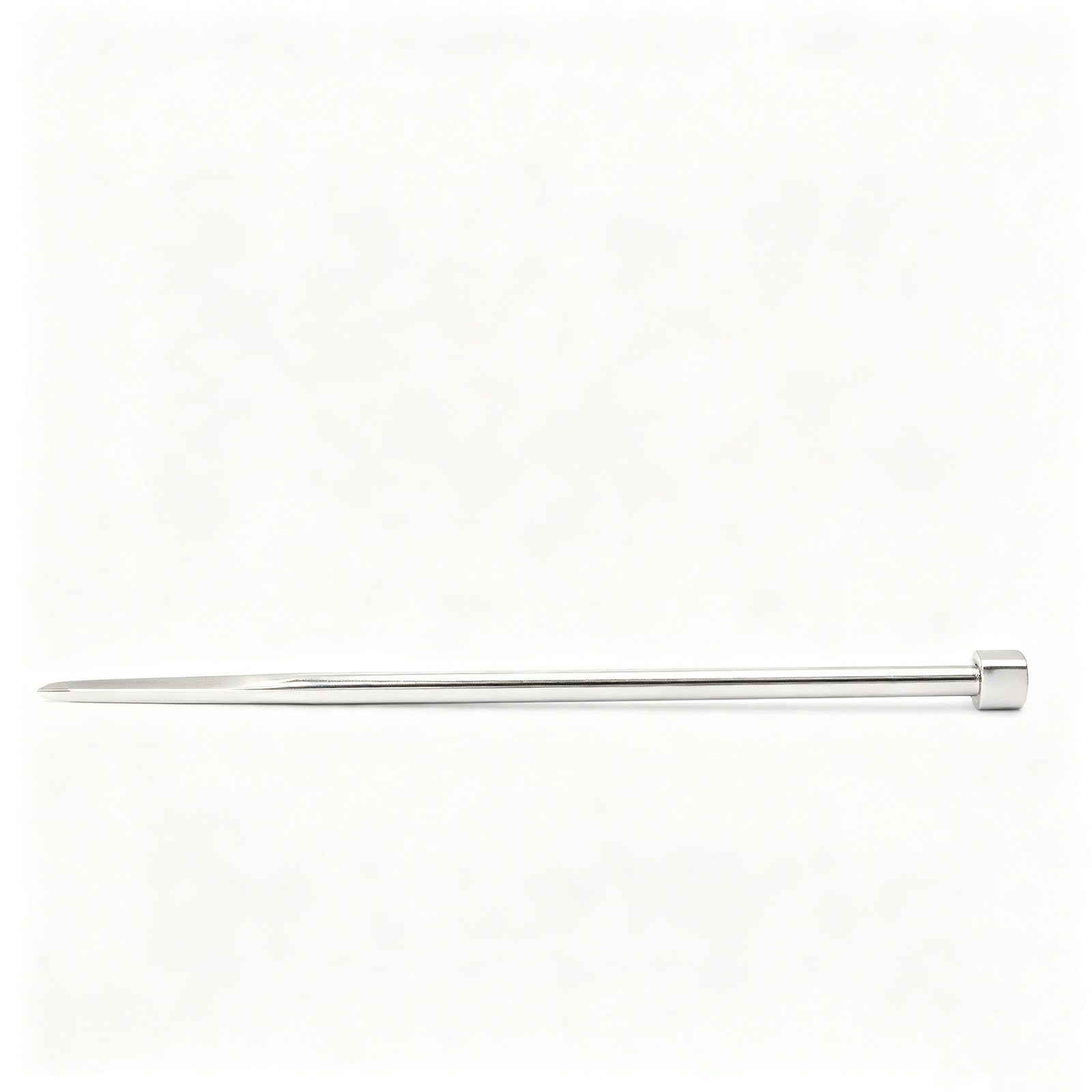
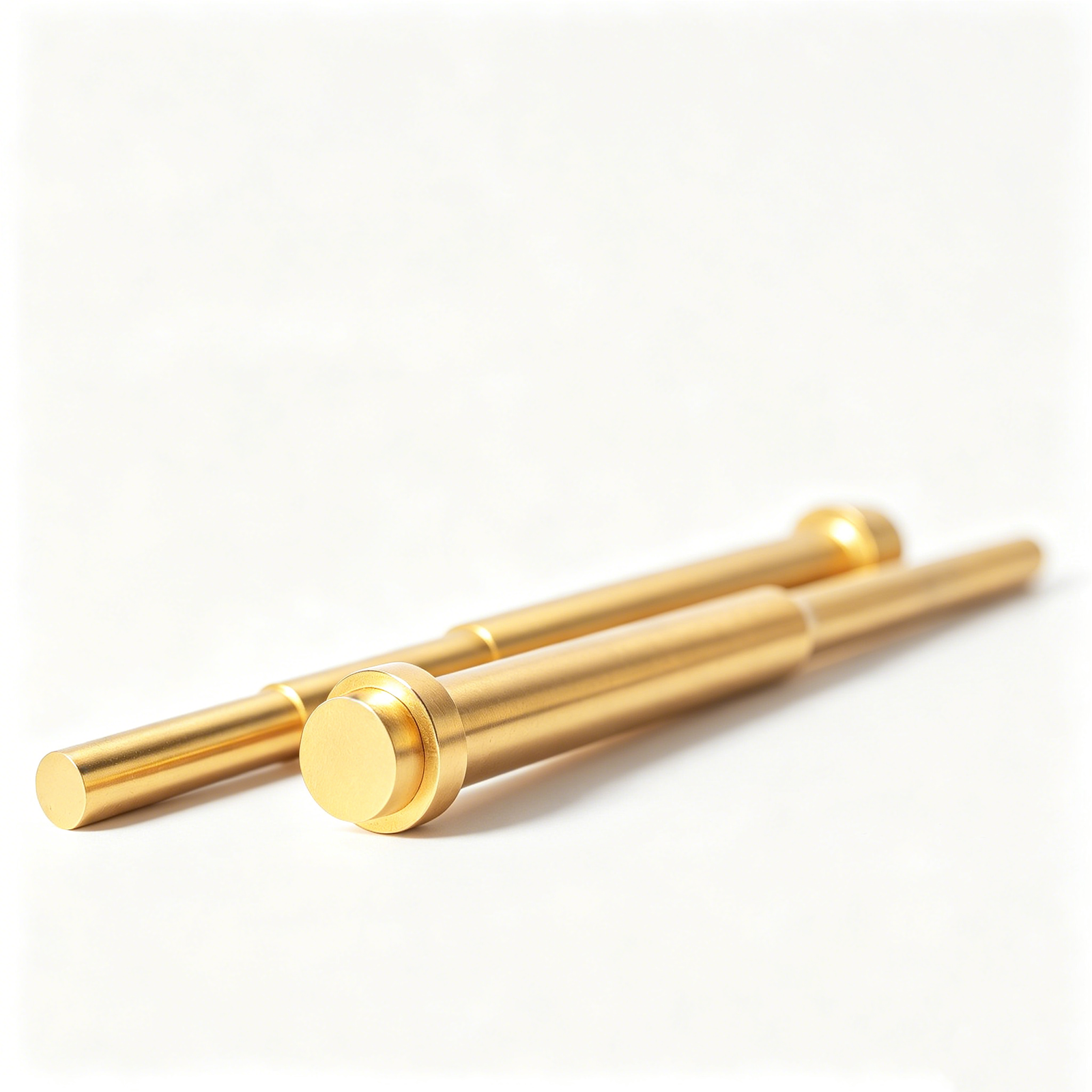


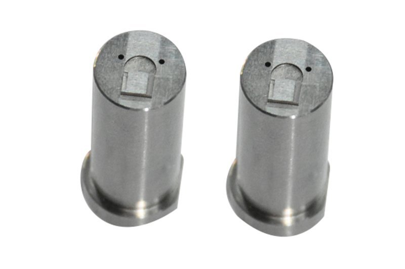

Related Drawing-Based Manufacturing Enquiries
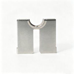

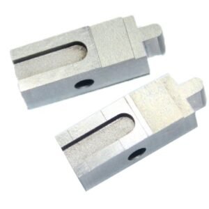


Custom CNC Machined Flanges: Engineering Advantages
A drawing-driven workflow that focuses production planning on functional interfaces, critical dimensions, and documented inspection requirements.
Drawing-Based DFM
Review drawings, models, and mating context early to identify tool access, datum strategy, machining allowances, and avoidable manufacturing risks.
Critical Dimension Focus
Prioritize bores, faces, bolt patterns, grooves, and locating features according to their function, tolerance relationships, and assembly requirements.
Process Route Planning
Coordinate CNC machining, EDM, grinding, and fitting where required by geometry, material condition, surface requirements, and feature accessibility.
Inspection Planning
Align inspection methods and reporting expectations with drawing-defined critical features before production, so verification supports the approved project requirements.
Revision-Controlled Communication
Keep drawing revisions, technical decisions, inspection expectations, and delivery information visible throughout the custom CNC machined flanges project.
Custom CNC Machining and Precision Part Families
Drawing-driven process routes for configurable precision parts, tooling components, and controlled low-volume manufacturing work.

Precision CNC Machining Services
Precision CNC machining services for drawing-based flanges, housings, plates, and custom parts where critical dimensions, datum references, material requirements, and inspection needs must be reviewed before quotation and production.
Upload a Drawing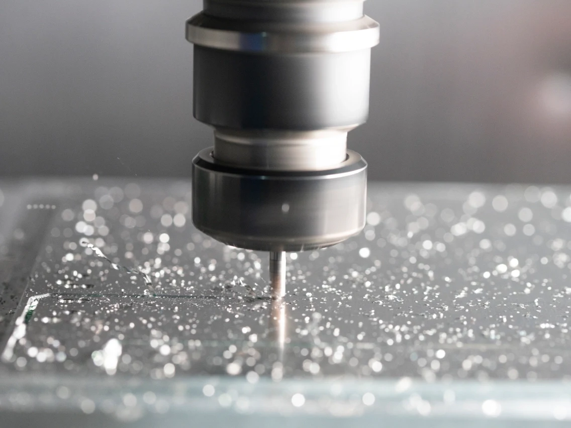
CNC Milling
Custom CNC milling services for prismatic flange features, mounting faces, ports, pockets, and bolt patterns. Machining access, clamping strategy, wall thickness, and tolerance relationships should be evaluated against the drawing and intended assembly.
Upload a Drawing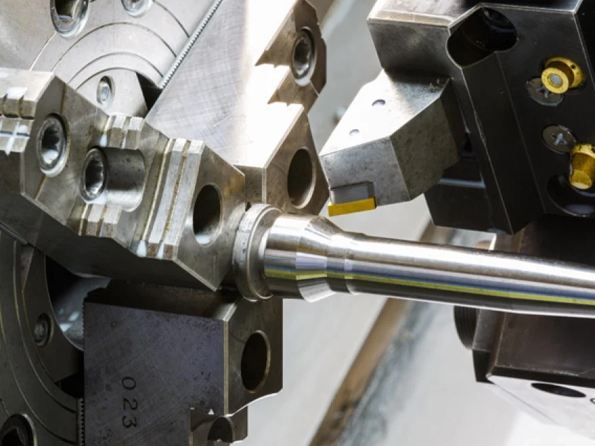
CNC Turning
Precision CNC turning services for rotational flange profiles, bores, threads, sealing diameters, shafts, and bushings. The process route should account for concentricity, runout, datum selection, material condition, and any secondary milling or grinding requirements.
Upload a Drawing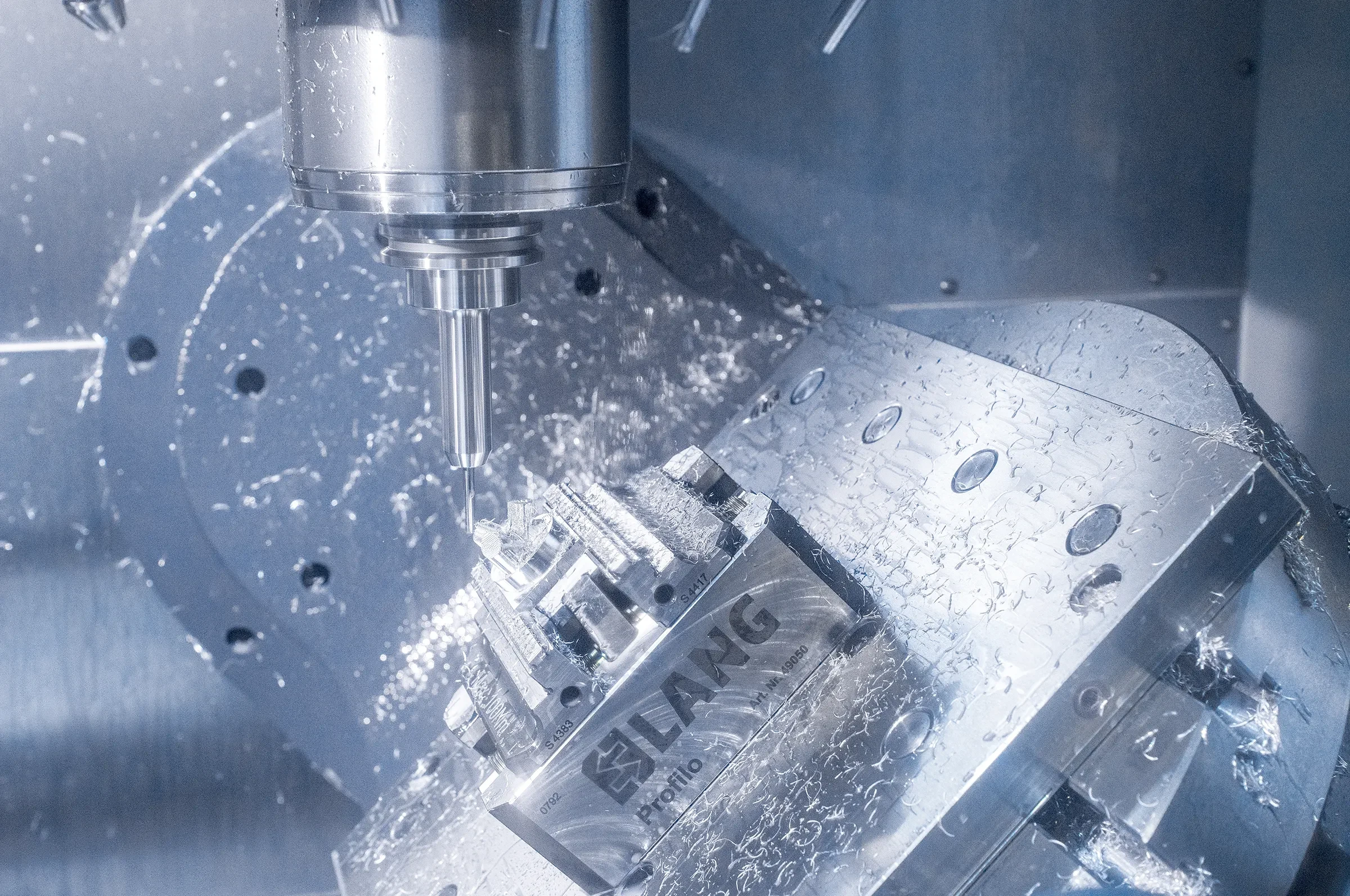
5-Axis Machining
5-axis CNC machining for complex flange geometries and precision components requiring multi-angle access. It can reduce repeated setups while supporting controlled relationships between faces, holes, contours, and features that are difficult to reach conventionally.
Upload a Drawing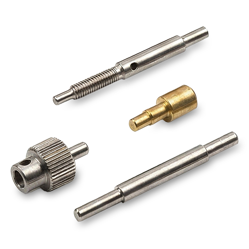
Swiss & Micro Machining
Swiss machining and micro machining for small-diameter pins, sleeves, connector elements, and compact precision parts. Buyers should identify critical diameters, length-to-diameter ratios, material condition, burr limits, and inspection requirements in the RFQ.
Upload a Drawing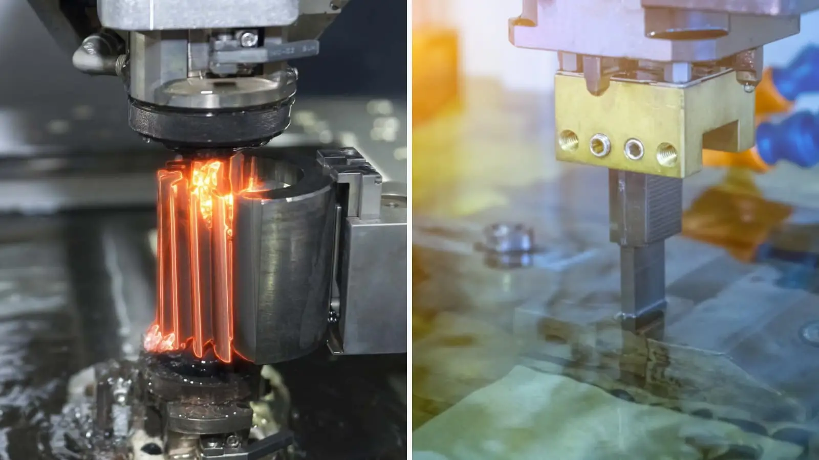
Wire EDM Services & Sinker EDM Services
Wire EDM and sinker EDM services for narrow slots, sharp internal geometry, hardened features, and complex mold details. Electrode strategy, wire path, recast-layer considerations, corner conditions, and finishing requirements require drawing review.
Upload a Drawing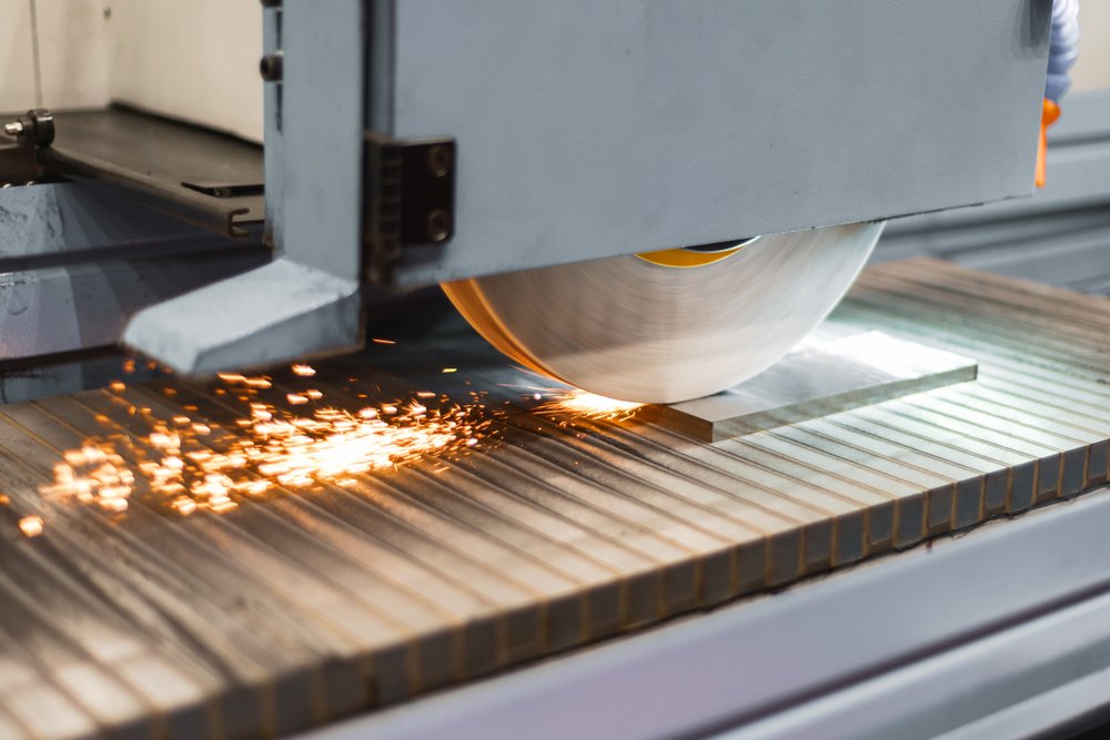
Precision Grinding
Precision surface and profile grinding for controlled flatness, parallelism, profile accuracy, and finish on hardened or precision-machined parts. Grinding stock, heat-treatment sequence, datum strategy, and final inspection method should be defined before release.
Upload a Drawing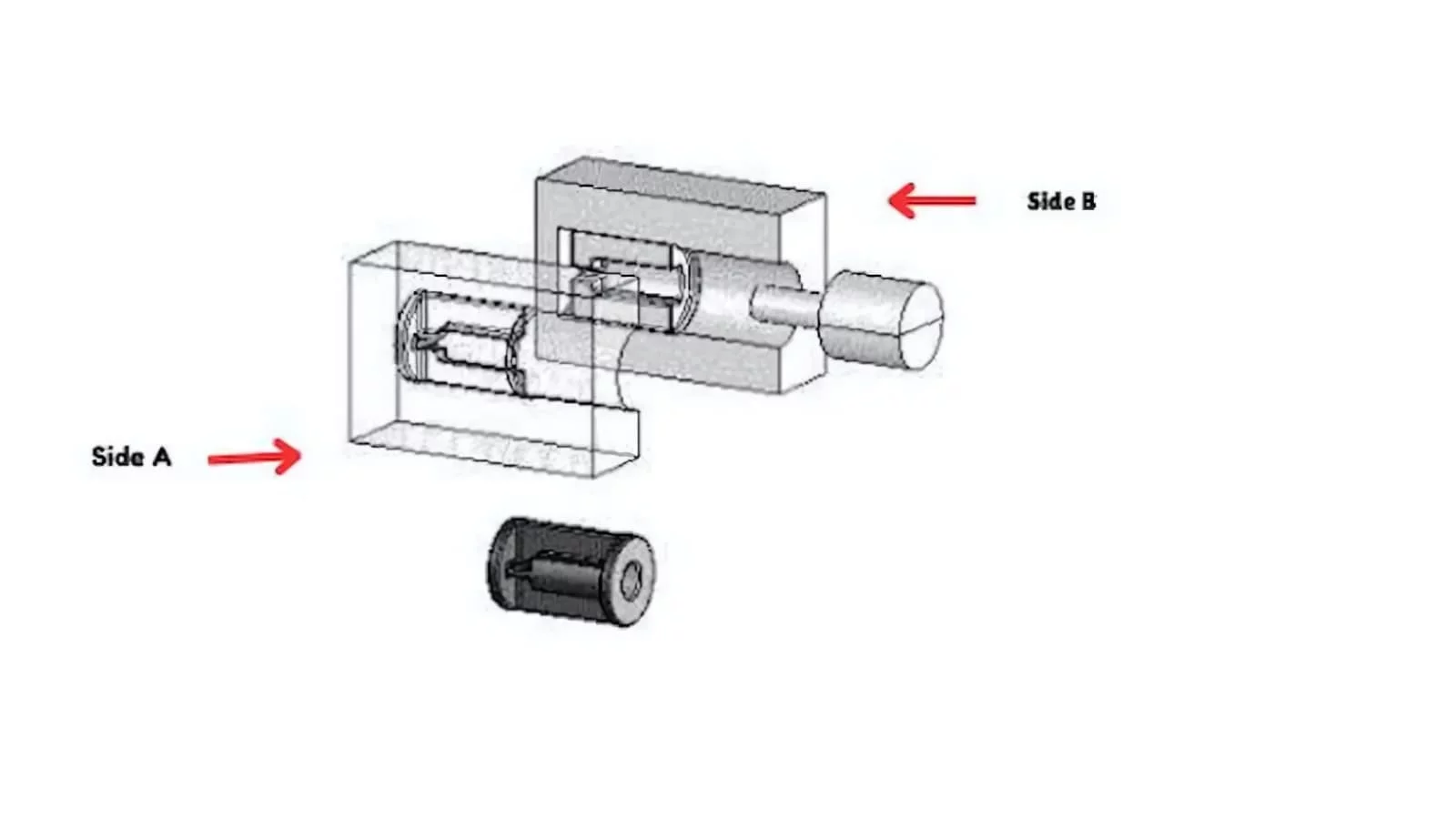
Mold Core Inserts & Mold Cavity Inserts
Precision mold core and cavity inserts manufactured from customer drawings for injection molding and related tooling. Critical parting surfaces, cooling interfaces, shutoffs, cavity details, material, heat treatment, EDM, and grinding requirements are reviewed as a coordinated process route.
Upload a Drawing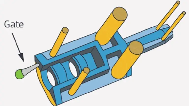
Ejector & Ejection Components
Ejector pins, sleeves, and ejection components for mold assemblies where fit, straightness, surface condition, and wear behavior affect reliable movement. Drawings should clarify mating bores, clearance expectations, material, heat treatment, and inspection priorities.
Upload a Drawing
Core Pins, Guide & Locating Components
Core pins, guide pins, and locating components produced for repeatable alignment and controlled mold function. Sourcing decisions should consider mating relationships, concentricity, hardness, surface condition, assembly clearances, and the datum scheme used for verification.
Upload a Drawing
Slides, Lifters, Gates & Mold Accessories
Mold slides, lifters, gates, and accessories manufactured as configurable tooling components rather than assumed stock items. Geometry, travel interfaces, shutoff conditions, wear surfaces, material treatment, fitting needs, and revision control should be established from the assembly context.
Upload a Drawing
Connector Mold Components
Precision connector mold components for tight-pitch, multi-feature tooling where small geometry and positional accuracy directly influence molded connector performance. Review should address cavity detail, pin or insert relationships, EDM access, grinding requirements, and inspection evidence.
Upload a Drawing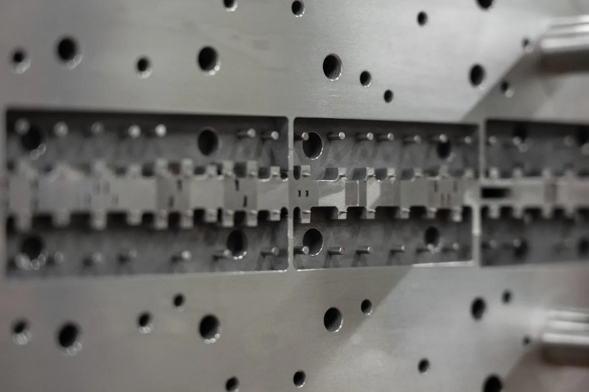
Stamping Die Components
Precision stamping die components for forming, blanking, piercing, and progressive-die applications. Material, heat treatment, edge condition, clearance relationships, guide interfaces, grinding stock, and wear surfaces should be specified in relation to the die assembly.
Upload a Drawing
Injection Mold Components for MIM, CIM & Overmolding Tooling
Injection, MIM, CIM, and overmolding tooling components within verified production scope. Each project is assessed from the drawing, resin or feedstock context, mold interface, critical geometry, material requirements, and the required CNC, EDM, grinding, fitting, and inspection route.
Upload a Drawing
Machining Materials
CNC machining materials selected against the drawing, application, machining behavior, heat-treatment condition, and inspection needs. Provide the specified grade, material standard, required condition, traceability expectations, and any approved substitution limits with the RFQ.
Upload a Drawing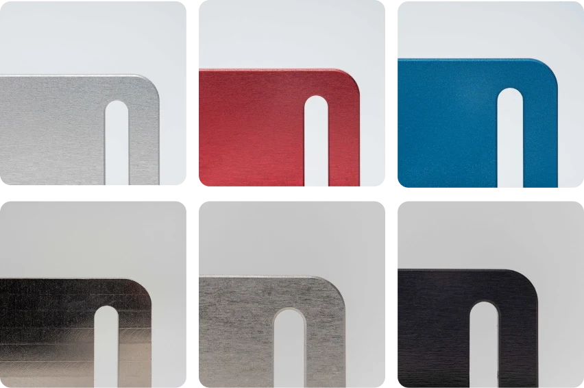
Surface Finishes & Heat Treatment
Surface finishing and heat treatment planned around functional surfaces, wear requirements, corrosion considerations, dimensional change, and final tolerance. Define the required treatment, finish areas, masking or post-process machining needs, and acceptance criteria before production.
Upload a Drawing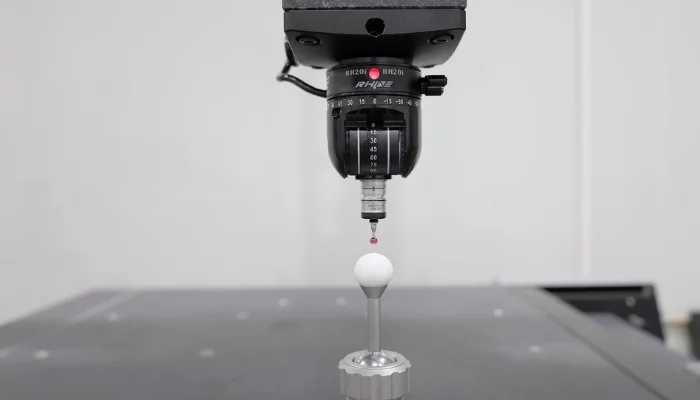
Quality, Metrology & Documentation
Precision inspection, metrology, and quality documentation aligned with the order and verified inspection plan. Identify critical dimensions, datums, measurement methods, reporting format, material evidence, revision level, and any customer-specific traceability requirements during review.
Upload a Drawing
Prototyping & Low-Volume Production
Rapid prototyping and low-volume manufacturing for drawing-based parts that need practical DFM feedback before broader release. Submit the drawing or model, quantity, material, critical dimensions, surface requirements, target date, and inspection expectations for process evaluation.
Upload a DrawingMaterials for Custom CNC Machined Flanges
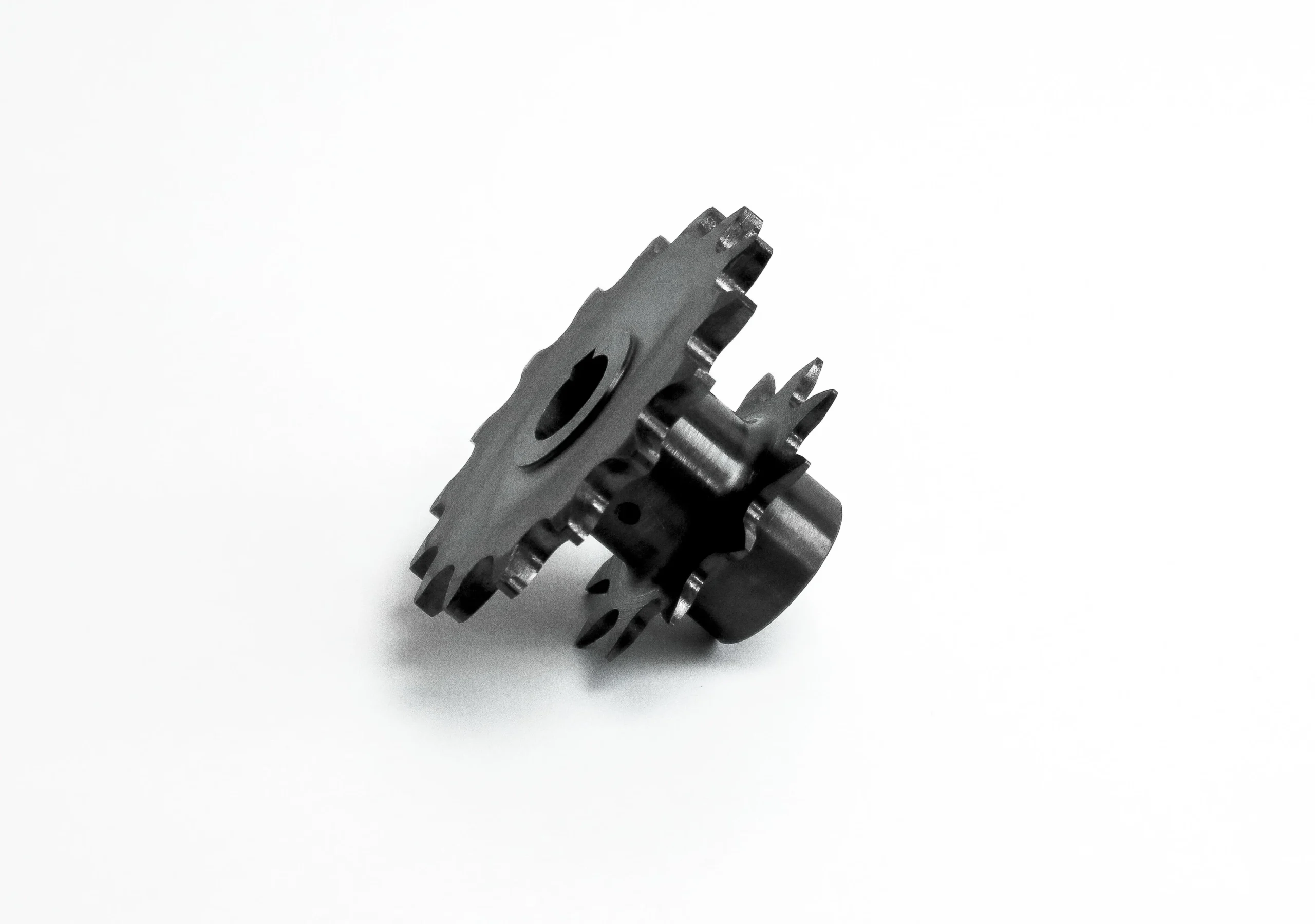
Carbon Steel
A practical choice for general industrial mounting and equipment interfaces where strength and cost matter. Grade, stock form, corrosion protection and heat-treatment needs should be confirmed against the drawing and operating environment.
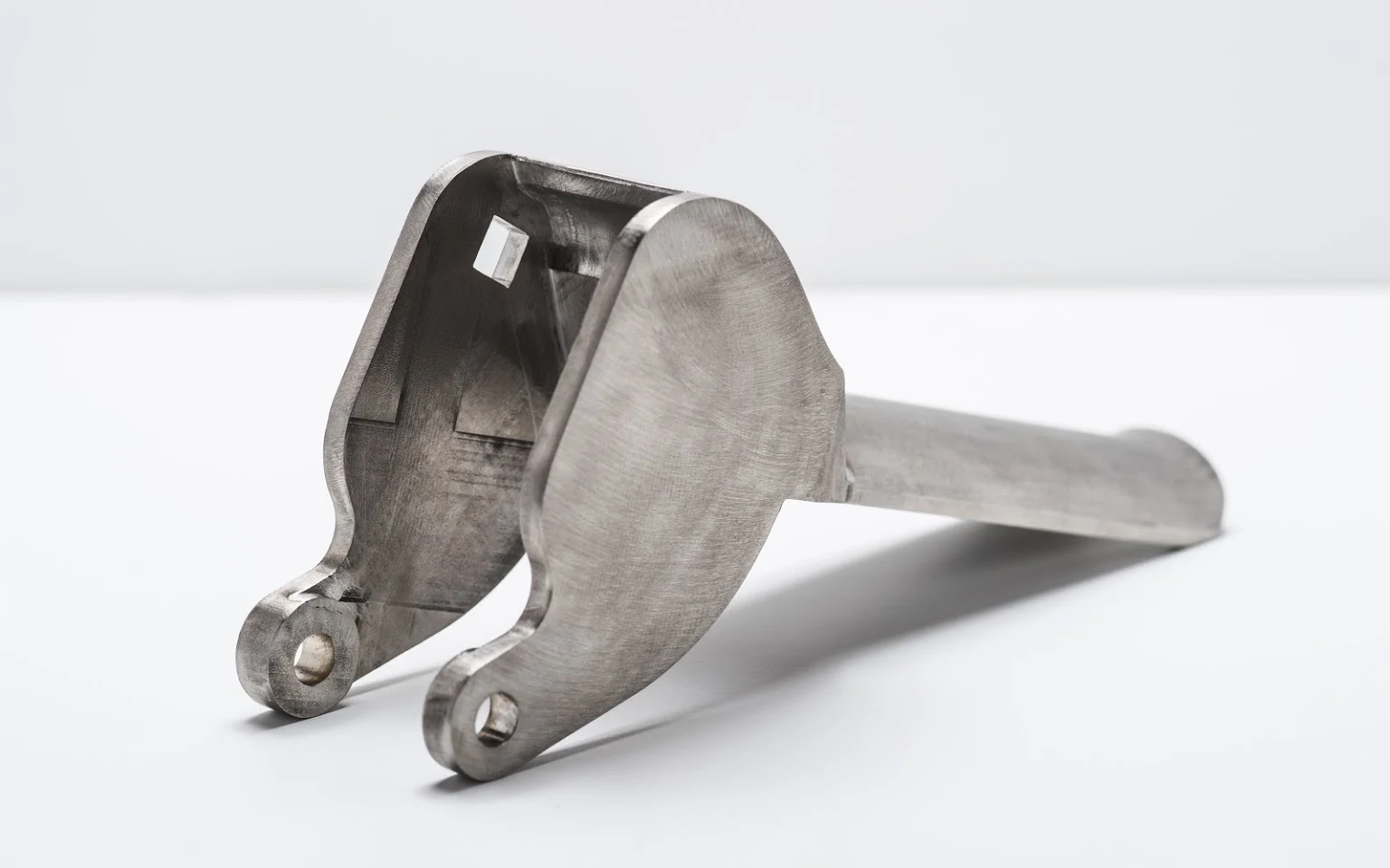
Alloy Steel
Used when a flange requires higher strength, fatigue resistance or a controlled heat-treatment route. Machining allowance, hardness condition, sealing-face finish and post-treatment inspection requirements need early engineering review.
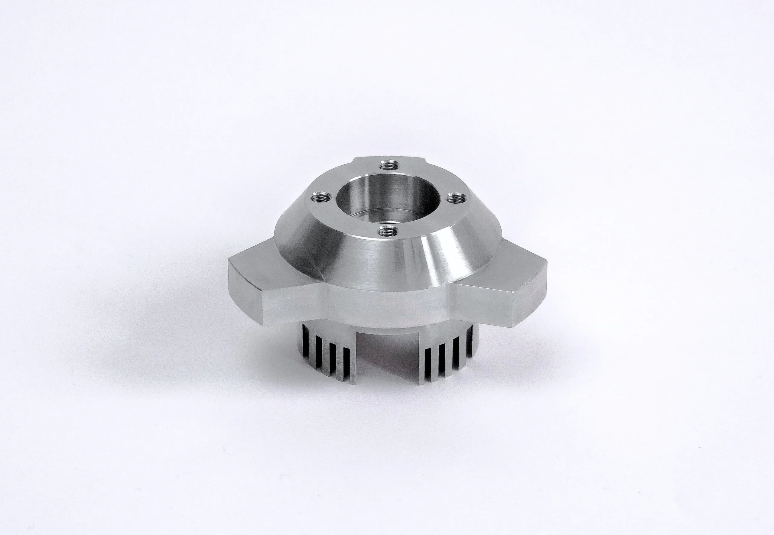
Stainless Steel
Considered for corrosive, washdown or moisture-exposed assemblies where material grade affects performance and machining behavior. The RFQ should identify the medium, mating materials, surface requirements and any required passivation or finishing.
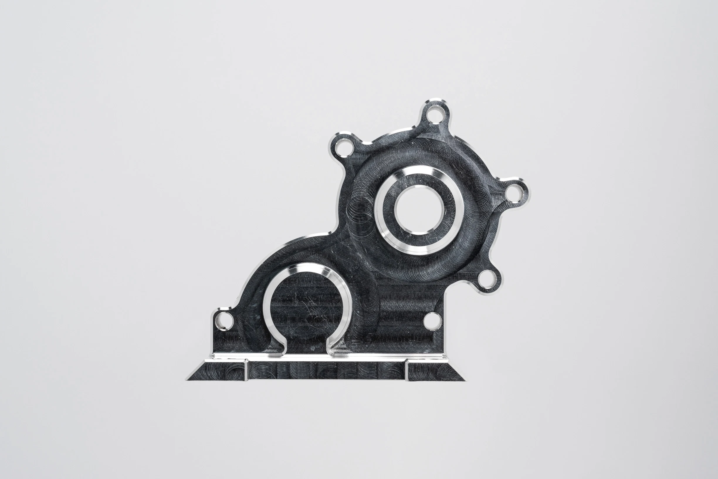
Aluminum Alloys
Suitable for weight-sensitive equipment flanges, adapter parts and non-corrosive assemblies when the drawing supports the application. Alloy temper, thread engagement, sealing geometry and protective finish should be evaluated with the mating interface.
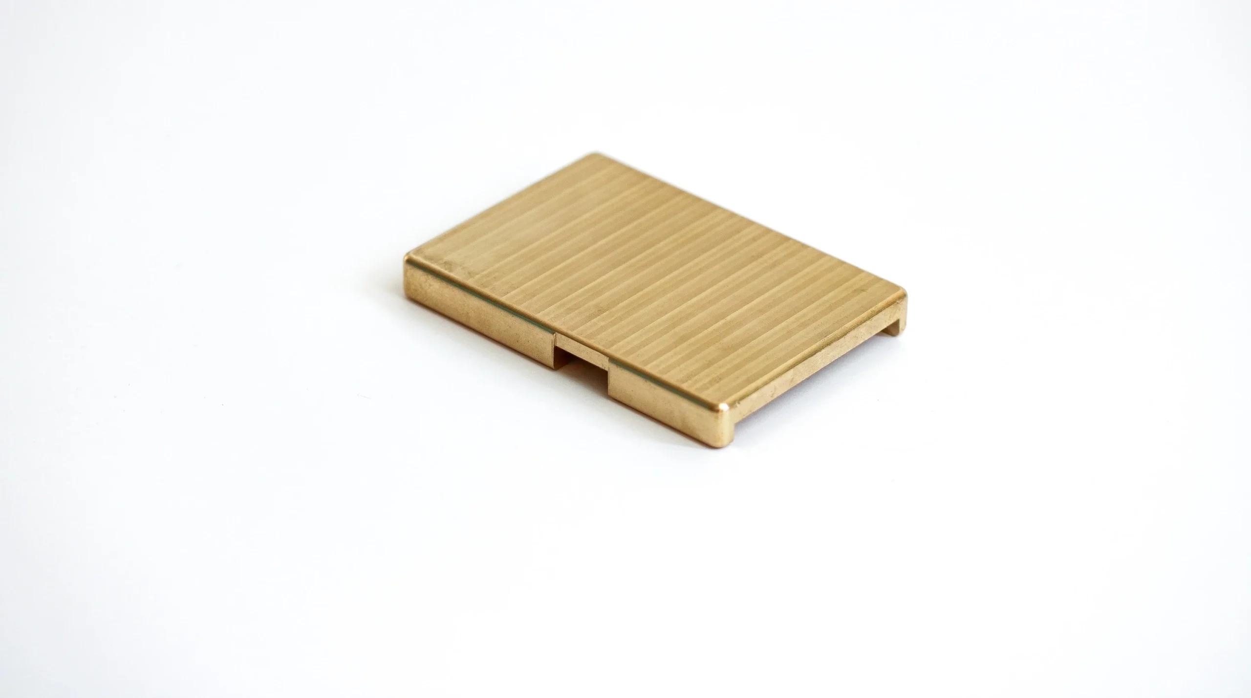
Brass Alloys
Often evaluated for specialized fluid, electrical or instrument interfaces requiring machinability and corrosion behavior appropriate to the application. Confirm the exact alloy, pressure conditions, thread details and compatibility with connected components before machining.
Custom CNC Machined Flanges: Critical Feature Processes
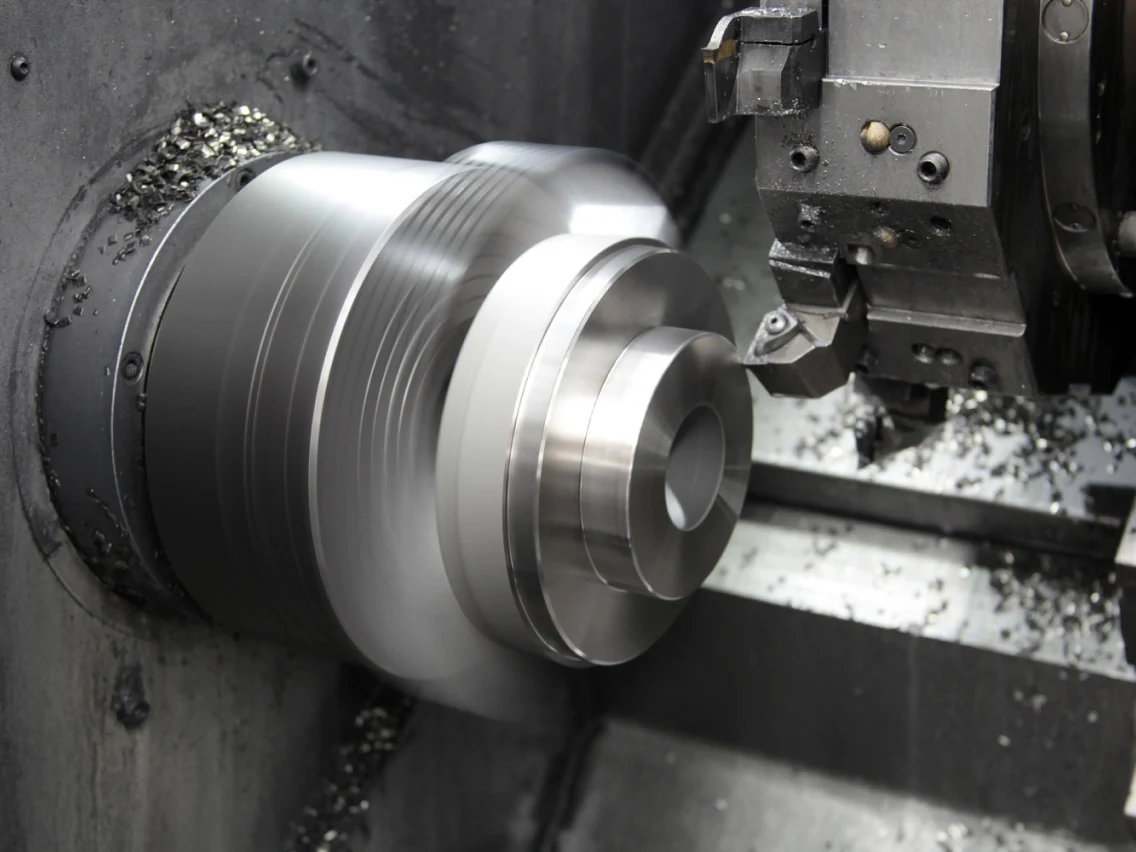
CNC Turning
Turning establishes flange outside diameters, center bores, steps and facing surfaces from controlled datums. Setup strategy is reviewed against concentricity, runout and sealing-face requirements before machining begins.
CNC Milling
Milling produces bolt patterns, mounting holes, flats, slots, keyways and non-round interface features. Programmed positions are coordinated to the drawing datums so mating relationships can be inspected clearly.
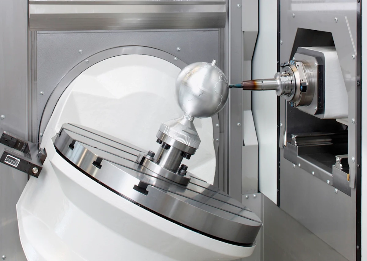
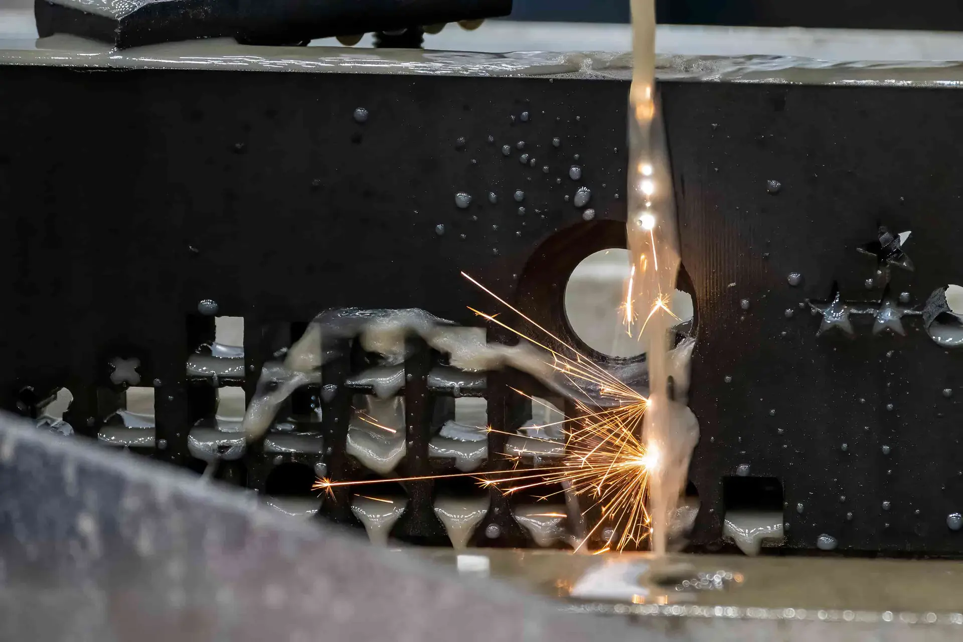
Wire EDM
Wire EDM can form precise through-profiles, narrow slots and conductive-material details where cutter access or internal corner geometry limits conventional machining. Wire path, start-hole location and final inspection criteria are defined from the drawing.

Precision Grinding
Grinding is considered for critical flatness, parallelism, thickness control and surface-condition requirements after the applicable machining or heat-treatment sequence. Allowance, datum protection and inspection method should be agreed before production.
Fitting and Inspection
Fitting and inspection verify the functional relationship of bores, bolt circles, sealing features and mating interfaces against the approved drawing. Critical dimensions, revision status and requested reports remain visible through final release.
Custom CNC Machined Flanges: Features, Marking and Finishing
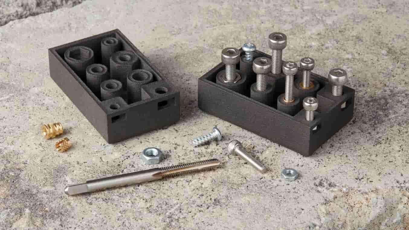
Threads and Inserts
Tapped holes, threaded ports and specified inserts can support fastening or mating interfaces. SUUXIANG reviews thread standard, engagement, material condition and tool access against the drawing before confirming a machining route.

Locating Features
Pilots, dowel holes, locating steps and shoulders establish repeatable alignment with mating components. Define the functional datum relationships and fit requirements so machining and inspection can focus on the features that control assembly.

Sealing Grooves
O-ring grooves, gasket lands and sealing recesses require clear profile, surface and datum requirements. Project review considers cutter access, machining sequence and how the finished feature will be verified against the specified interface.
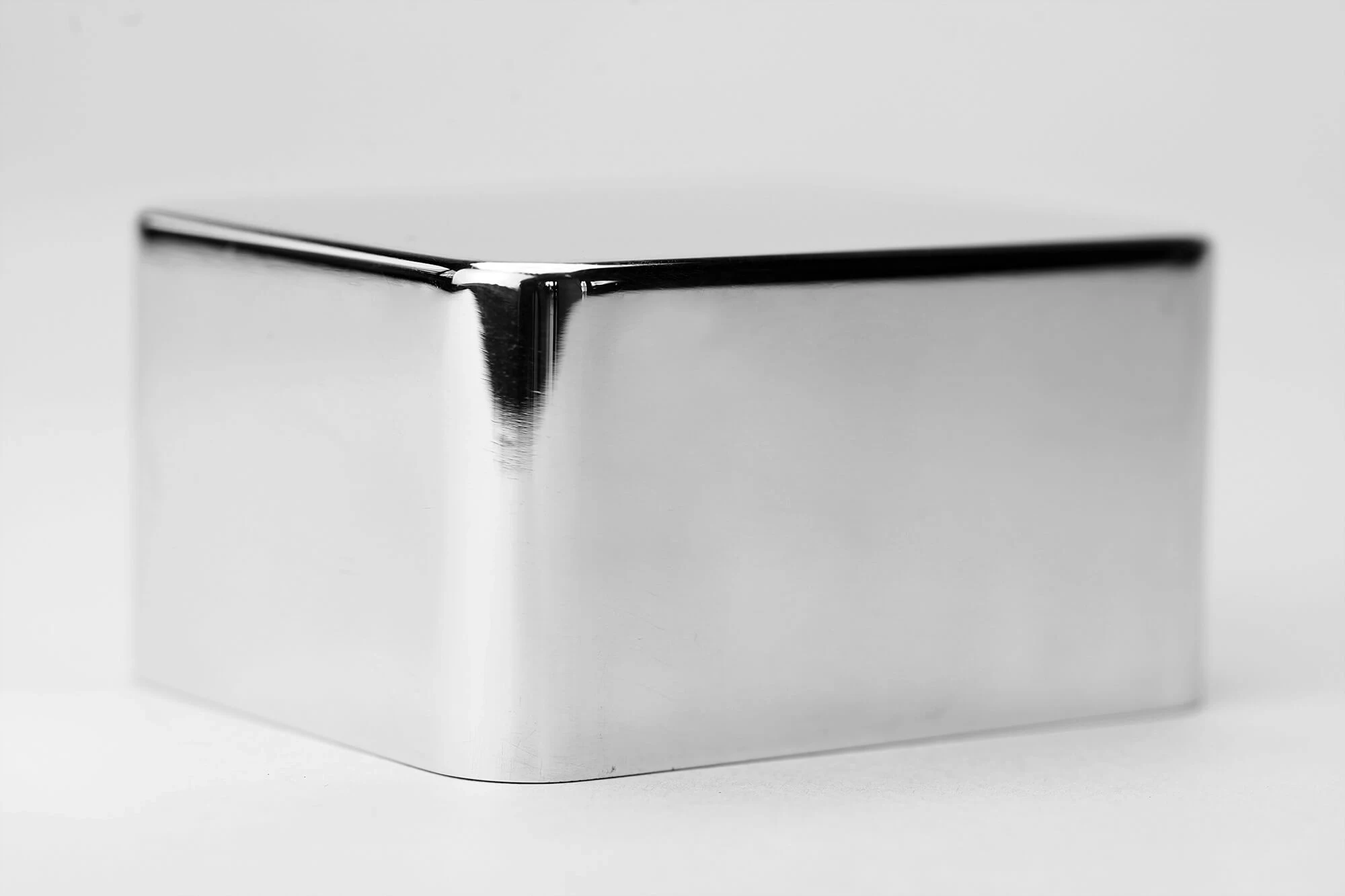
Surface Finishing
Coating, plating, passivation or other drawing-specified finishing can be evaluated for the selected material and application. Critical faces, bores and threads should be identified early where masking, allowance or post-finish machining may be needed.
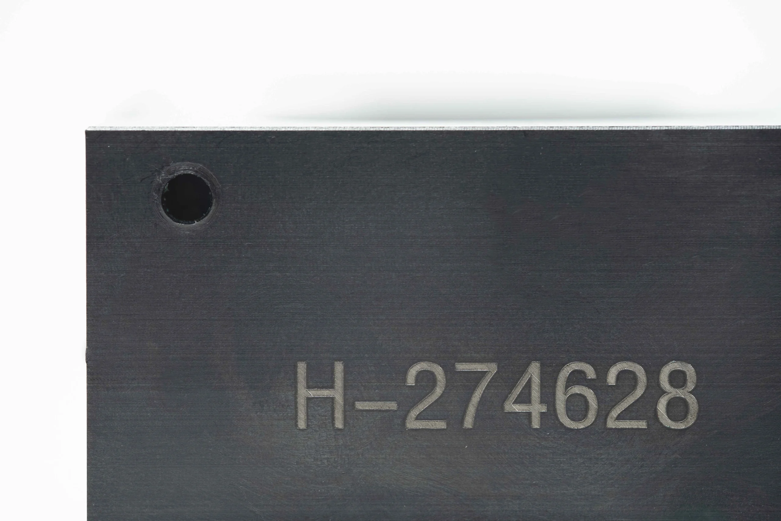
Part Marking
Laser marking, engraving or other specified identification can help support part recognition and revision traceability. Provide the required content, location and legibility constraints so marking does not interfere with sealing, mating or inspection surfaces.
About SUUXIANG Custom CNC Machined Flanges
SUUXIANG is the international-facing precision-manufacturing brand of Dongguan SuuXiang Precision Mold Co., Ltd., established in 2010 in Chang’an Town, Dongguan, Guangdong, China. We help global engineering and sourcing teams turn drawings, models, and specifications into inspected custom CNC machined flanges, precision mold components, connector tooling, and related custom parts.
Our workflow begins before quotation with drawing review, DFM discussion, and identification of critical dimensions, datums, material requirements, machining access, and inspection expectations. CNC milling and turning, multi-axis machining, EDM, grinding, fitting, and inspection are planned around the project’s actual geometry and verification needs.
What distinguishes SUUXIANG is disciplined coordination from revision-controlled input through inspection documentation and delivery communication. We do not treat a drawing as a generic order: we review feature relationships, process sequence, and quality evidence so buyers can make informed decisions before production commitments are made.

How SUUXIANG Controls Custom CNC Machined Flanges
Drawing Review Before Commitment
SUUXIANG reviews the drawing, 3D model, mating interface, material, quantity, and quality expectations before committing to a route for custom CNC machined flanges. The discussion identifies functional relationships that can affect manufacturability, inspection, and assembly.
- Confirm critical dimensions, datums, and tolerance relationships
- Review bores, bolt circles, sealing faces, grooves, and threads
- Identify mating-part information needed for functional fit
- Clarify revision status and required delivery documentation

Process Routes Match Geometry
CNC turning, milling, multi-axis machining, wire EDM, sinker EDM, and grinding are selected around the actual flange geometry rather than applied as a fixed sequence. Tool access, setup control, electrode strategy, and machining allowance are reviewed before production planning.
- Use turning for rotational faces, bores, and diameters
- Plan milling for hole patterns, flats, slots, and secondary features
- Assess EDM where internal geometry or access limits conventional cutting
- Sequence heat treatment and finish operations around dimensional priorities

Grinding and Fitting Control Interfaces
Where the drawing calls for a controlled functional interface, SUUXIANG evaluates grinding stock, surface requirement, and fitting needs alongside the machining route. This helps keep critical faces, locating steps, and mating relationships visible throughout production of custom CNC machined flanges.
- Reserve appropriate stock when grinding is required
- Review face condition against sealing or locating function
- Control feature relationships through planned setup strategy
- Address burr removal and edge condition before final inspection
Inspection Follows the Drawing
Inspection planning is tied to the released drawing and agreed critical-to-quality requirements. SUUXIANG aligns measurement methods, reporting needs, revision identification, and order documentation so the final record corresponds to the verified inspection plan and supplied part revision.
- Define inspection priorities for critical dimensions and geometry
- Confirm required reports before production begins
- Maintain visible revision and order traceability
- Match final documentation to the approved inspection plan
Custom CNC Machined Flanges: A Drawing-Driven Difference
Compare evidence-led review and inspection alignment with a typical RFQ-only machining supplier.
← Swipe left or right to view →
Custom CNC Machined Flanges: From Drawing Review to Shipment
A drawing-driven path that keeps critical features, inspection expectations, revisions, and delivery requirements visible before production begins.
RFQ and Drawing Intake
Share the 2D drawing, 3D model when available, material, quantity, application context, delivery target, and required inspection or documentation expectations.
DFM and Critical Review
SUUXIANG reviews datums, critical dimensions, tolerance stack, tool access, stock selection, heat-treatment sequence, and flange features requiring special process planning.
Process Route Confirmation
The agreed route assigns CNC turning, milling, drilling, EDM, grinding, fitting, or finishing only where the drawing and verified project requirements justify them.
Controlled Part Manufacturing
Production follows the confirmed revision, with machining allowances and feature relationships managed across setups to protect bores, faces, bolt patterns, and locating geometry.
Inspection and Delivery Coordination
Finished parts are inspected against the agreed plan, documented as required, packed for shipment, and coordinated with the customer’s order revision and delivery information.
Start Your Custom CNC Machined Flanges Project
Move from drawing review to inspected delivery with requirements, critical features and revision details visible at each decision point.
Submit Your Drawing Package
Share the 2D drawing, 3D model when available, material, quantity, target date, inspection needs, and mating-component context for a focused technical review.
Confirm DFM and Quotation
Review critical dimensions, datums, machining access, surface requirements, heat-treatment sequence, and inspection expectations before SUUXIANG finalizes the proposed process route and quotation.
Approve Samples When Needed
For projects requiring validation, align on sample scope, measurement evidence, revision status, and acceptance criteria before authorizing repeat production or subsequent operations.
Coordinate Production and Delivery
SUUXIANG coordinates machining, EDM, grinding, fitting, inspection, documentation, and delivery updates against the approved drawing revision and verified project requirements.
Customer Evidence for Custom CNC Machined Flanges
Custom CNC Machined Flanges: Customer Project Outcomes
Verified customer outcome pending. Reserve this position for an approved case study documenting a measurable improvement in drawing clarity, inspection results, revision control, or delivery coordination.
Verified customer outcome pending. Reserve this position for an approved testimonial that identifies the flange project scope, the documented result, and the customer-approved performance measure.
Verified customer outcome pending. Reserve this position for an approved testimonial covering a specific drawing-based flange order, inspection requirement, revision milestone, or coordinated delivery outcome.
Custom CNC Machined Flanges FAQ
Practical RFQ, documentation, sampling, and delivery questions for drawing-based flange projects.
What information do you need to quote custom CNC machined flanges?
Is there an MOQ for custom CNC machined flanges?
Can I order a sample of custom CNC machined flanges before production?
How long does flange machining take?
Which drawing formats can I send for a flange RFQ?
What materials can be used for custom CNC machined flanges?
Can you provide inspection reports and material documentation?
How are payment, shipping, and IP protection handled?
The Complete Buyer’s Guide to custom cnc machined flanges
Use this decision framework to define functional requirements, compare materials and machining options, evaluate supplier quality controls, and avoid specification mistakes that cause sealing, fit, cost, or delivery problems.
1. What Are Custom CNC Machined Flanges?
One custom cnc machined flange is a drawing-defined interface that joins, locates, mounts, seals, or transfers load between two components. Its functional requirements come from the mating assembly, datums, loads, fluid path, and specified inspection criteria—not from a generic catalog description.
ASME B16.5-style pressure-piping flanges use standardized size, pressure-class, facing, material, and marking requirements; a non-standard machined part does not acquire a pressure rating merely because it has a circular bolt pattern. Custom mechanical, hydraulic, tooling, or connector flanges may instead be designed around a pump housing, machine frame, mold plate, connector body, or proprietary mating geometry.
Six recurring features define the interface: center bore, bolt circle, mounting face, sealing groove, hub, and locating step. The drawing should identify which feature establishes location, which face controls contact or sealing, and which holes carry clamp load, so machining and inspection can follow the actual assembly function.
2. Evolution of CNC Flange Manufacturing
2D drawings and 3D CAD models now define the production baseline for custom cnc machined flanges, replacing reliance on nominal catalog dimensions or manual layout. A controlled file set lets the buyer identify datums, revision level, bore-to-face relationships, bolt-circle position, and critical mating features before stock is cut.
CNC turning established repeatable control of concentric diameters, bores, hubs, and faces; CNC milling then made slots, flats, cross holes, tapped features, and asymmetric patterns practical without treating them as separate manual operations. Modern process planning uses the drawing and CAD model to select setup order, tool access, workholding, and machining allowance (https://jlccnc.com/blog/flange-machining).
Probe routines and documented inspection changed the sourcing question from whether a flange looks correct to whether its specified feature relationships were verified. For prototype iterations, send the changed model and revised 2D drawing together, then require the supplier to confirm revision control, measurement method, and any effect on the machining route before repeat production.
3. Types of Custom CNC Machined Flanges
Custom cnc machined flanges are best classified by the interface they control, not by outside diameter alone. The drawing should define the mating component, datums, bolt pattern, bore, face, and any sealing requirement.
Mounting And Adapter Flanges
Mounting, pump, and motor adapters locate equipment through a pilot bore or register while transmitting clamp load through holes or studs. Turning establishes concentric diameters; milling adds patterns, keyways, ports, and clearance features.
Required drawing data includes mating pilot dimensions, bolt-circle coordinates, thread callouts, datum scheme, and allowable runout.
Hydraulic And Blind Covers
Hydraulic flanges commonly combine a port bore, sealing face, O-ring groove, and fastener pattern; blind covers close an opening without a flow bore. Turning or milling is selected from geometry, followed by controlled groove and face inspection.
A custom interface must not be assumed to carry an ASME or other standard pressure rating unless the specified standard, material, dimensions, facing, and validation requirements are confirmed.
Weld Interfaces And Retaining Rings
Weld-neck-style interfaces use a hub and bore transition to mate with pipe or a fabricated assembly, while retaining rings use grooves, tabs, or holes to constrain another component. CNC turning produces round hubs and ring profiles; milling handles non-round outlines, flats, slots, and multi-feature variants.
Required data includes weld preparation, mating bore, groove profile, wall thickness, orientation, and post-weld machining requirements.
4. Materials for Custom CNC Machined Flanges
Six material families cover most custom cnc machined flanges, but service conditions determine the viable grade. Specify the exact grade, stock form, temper or heat-treatment condition, certification requirement, and media-temperature exposure on the RFQ.
| Material | Strength / Weight | Corrosion Or Media | Typical Stock / Finish |
|---|---|---|---|
| Aluminum | Moderate / light | Limited without protection | Plate or bar; anodize |
| Carbon steel | High / heavy | Needs coating in wet service | Plate, bar, forging; paint or plating |
| Alloy steel | High / heavy | Condition-dependent | Bar or forging; heat treat, coat |
| Stainless steel | Moderate-high / heavy | Good, grade-dependent | Plate or bar; passivate |
| Brass or bronze | Moderate / dense | Selected media compatibility | Bar; polish or plate |
| Engineering plastics | Low-moderate / light | Grade and fluid dependent | Plate or rod; usually uncoated |
Metal Selection Trade-Offs
6061-T6 reduces weight and machines readily; carbon and alloy steels provide higher load capacity but usually need corrosion protection. 304 or 316 stainless suits many corrosive environments, while brass or bronze can suit selected media and low-friction interfaces.
Stock And Finish Compatibility
Plate, bar, forged blanks, and ring stock change grain flow, available thickness, machining allowance, and cost. Confirm whether anodizing, plating, passivation, black oxide, paint, or no coating may alter sealing faces, threads, bores, or electrical contact surfaces.
Plastics Need Functional Review
PEEK, nylon, and acetal can reduce mass and resist selected chemicals, but their stiffness, creep, temperature limit, and sealing behavior differ from metals. Provide pressure, bolt preload, fluid, temperature, and mating-material data before selecting an engineering plastic.
5. Custom CNC Machined Flanges: Features and Finishes
2D drawings should define every interface, not merely the outside diameter. For custom cnc machined flanges, secondary features must be tied to datums and mating-part function before routing is released.
| Requirement | Drawing Definition | Process Control |
|---|---|---|
| Bore or thread | Size and datum | Gauge or inspection method |
| Sealing groove | Profile and surface | Mask or finish-machine |
| Coating area | Type and excluded zones | Masking and traceability |
Interface Geometry
Bores need diameter, depth, tolerance, and thread callout where applicable.
Bolt patterns need hole quantity, PCD, clocking datum, and through or tapped condition.
- O-ring or gasket groove profile
- Locating diameters and shoulders
- Keyways, flats, slots, and ports
Functional Surface Protection
Sealing faces, close fits, and electrical contact pads are functional surfaces, not cosmetic areas.
Masking before coating or post-finish machining may be required to preserve dimensions, face condition, and conductivity.
Finish And Identification
Deburring requirements should state allowable edge break and prohibited burr locations.
Coatings, passivation, plating, paint, laser marks, engraving, or dot peen marks need location and process sequence on the drawing.
6. Critical Construction and Quality Elements
For custom cnc machined flanges, assembly performance depends on controlled feature relationships, not individual diameters alone. Put functional datums and verification requirements on the released drawing before machining begins.
Datum And Geometric Control
Datum A should normally be the functional sealing or mounting face; select the bore or pilot as datum B when it locates the mating part. Apply true position to bolt holes and concentricity or runout controls to rotating bores relative to those datums.
Coordinate measurement or a dedicated functional gauge should verify the specified datum scheme. First-article review should confirm that the inspection setup reproduces the drawing’s datum order.
Mating Face Requirements
Flatness, parallelism, and perpendicularity should be tied to the surfaces that transmit clamp load or establish alignment. State the measuring method where part size, stiffness, or surface condition can affect the result.
Specify sealing-face texture by the required roughness value and lay direction, plus any groove profile. Do not leave gasket-contact finish to a general machining note.
Threads Edges And Traceability
Thread callouts should identify size, pitch, class, depth, and any gauging requirement; use go/no-go gauges where applicable. Define burr limits and edge breaks so sharp edges cannot damage seals, hands, or mating components.
Material traceability should link the supplied stock record, part revision, heat-treatment requirement, and final inspection report to the order. Review these records with the first article when they are contractually required.
7. How to Choose a Flange Manufacturer
For custom cnc machined flanges, select a supplier on evidence from your drawing—not a capability list. Compare the proposed process route, inspection plan, and revision-control method before price.
Engineering Review And Capacity
A 2D drawing and 3D model should trigger questions on datums, bore-to-face relationships, bolt circle, sealing surface, and tool access. Confirm which turning operation establishes concentric features and which milling setup produces non-round details.
Two proposed setups are often more revealing than a generic machine list. Ask how the part will be supported, reclamped, and protected from face distortion.
Material And Quality Evidence
A material certificate should identify grade, condition, and traceable heat or batch when the order requires it. Request the supplier’s plan for incoming verification, heat treatment, finishing coordination, and protection of critical sealing areas.
A first-article report should identify measured CTQs, instruments, datum references, and acceptance criteria. Ask for sample inspection records and the documented process for nonconformance and drawing revisions.
Launch And Communication Controls
A quoted lead time should separate material procurement, machining, outside processing, inspection, and shipment instead of offering one unsupported date. Confirm the time-zone contact, response window, and escalation owner.
One prototype approval should freeze the revision, process assumptions, and finishing requirements before repeat production. Provide quantity, target date, mating-part context, required reports, and any approved sample or gauge data.
8. Common Custom Flange Sourcing Mistakes
Most flange failures begin before machining, when the release package leaves functional relationships open to interpretation. For custom cnc machined flanges, resolve those gaps during drawing review and record the accepted inspection basis.
Mating Data And Datums
A 2D drawing without the mating flange, gasket, O-ring, or interface model can yield a part that bolts on but will not seal or locate. Provide mating-part geometry, assembly purpose, and the controlling datum scheme.
A bolt circle located from an unspecified datum can be nominally correct yet misaligned in assembly. Identify datum A, B, and C and relate bore, face, and holes to them.
Functional Requirements
A nominal dimension is not a functional tolerance. Mark bore-to-face runout, flatness, position, and any sealing-face roughness; otherwise inspection may accept a part that leaks or binds.
A material callout without medium, temperature, load, corrosion, and heat-treatment context invites an unsuitable selection. State service conditions and required material condition before release.
Finish, Standards, And Approval
A coating can add thickness and change thread, bore, sealing-face, or grounding fit. Specify finish, masked surfaces, buildup allowance, and whether final dimensions apply before or after coating.
A standard-looking flange is not automatically standards-compliant, and a first article is not meaningful without acceptance criteria. Name the applicable standard requirements, inspection methods, report format, and first-article measurements before production release.
9. Steps to Launch a Flange Project
A flange launch begins when engineering defines the operating medium, temperature, load, pressure context, and mating interface. SUUXIANG can then review the released inputs against manufacturability and inspection needs.
Define Functional Interfaces
Engineering should identify the sealing face, bore, bolt circle, locating features, datum scheme, and critical-to-quality dimensions. Procurement should attach the mating-part context so functional requirements are not inferred from geometry alone.
Release A Controlled Package
A complete RFQ should include a revision-controlled 2D drawing, 3D model when available, material condition, heat-treatment sequence, finish, quantity, and target date. Quality should state acceptance criteria, measurement method, report format, and any first-article requirement before quotation.
Approve And Maintain Production
SUUXIANG should return DFM questions and quotation assumptions for engineering, procurement, and quality to resolve jointly. After sample or first-article approval, record the approved revision, inspection plan, and change owner; no drawing, material, or acceptance change should proceed without documented authorization.
10. Custom CNC Machined Flanges: Pricing and Cost
Two cost patterns dominate custom cnc machined flanges: prototype orders absorb programming, setup, workholding, and first-article effort; repeat orders spread those costs across more pieces. SUUXIANG should quote from the controlled drawing revision, required material condition, blank form, and inspection plan rather than publish fixed prices.
One practical cost reduction is to combine compatible turned, drilled, and milled features into fewer setups while retaining the functional datums. Use tolerances, surface finish, coating masks, and report requirements only where mating or sealing function needs them; stable repeat releases can justify dedicated planning, material purchasing, and more predictable delivery.
| Quantity tier | Setup or programming impact | Main per-unit cost drivers | Typical lead-time drivers |
|---|---|---|---|
| 1–5 prototypes | High share per part | Material and blank availability; complex faces, bores, bolt patterns, grooves; tight CTQ tolerances; first-article report | Drawing review, material confirmation, machining route, inspection planning |
| 6–50 pieces | Setup is spread across the batch | Cycle time, extra orientations, EDM or grinding, finishing, dimensional report scope | Blank preparation, queued operations, outsourced treatment if specified |
| 51–250 pieces | Repeat setup can be optimized | Blank yield, tool life, feature consolidation, sampling versus 100% inspection | Released revision, material lot timing, process capacity |
| Repeat releases | Planning cost declines when revision is stable | Annual demand visibility, call-off size, packaging, traceability and documentation level | Forecast quality, material scheduling, agreed inspection frequency |
Upload Custom CNC Machined Flanges Drawings for Review
Send your 2D drawing, 3D model where available, material, quantity, critical dimensions, quality requirements, and target delivery date for quotation.