
Custom CNC Machined Shafts, Reviewed Before Production
Submit drawings for custom CNC machined shafts with DFM, critical-dimension review, process planning, and inspection requirements aligned before production.
Representative Custom CNC Machined Shaft Components


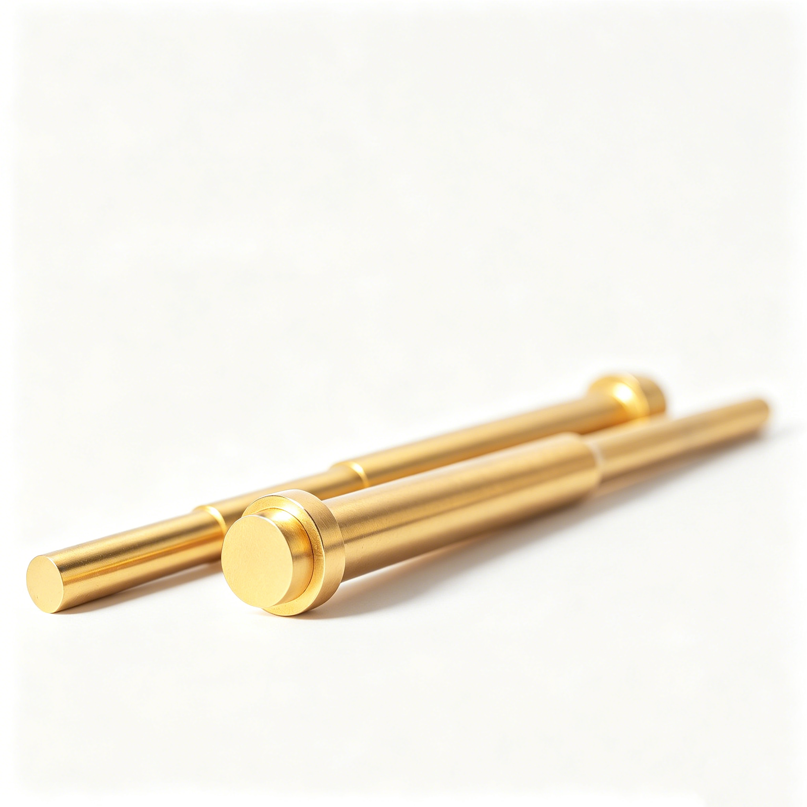


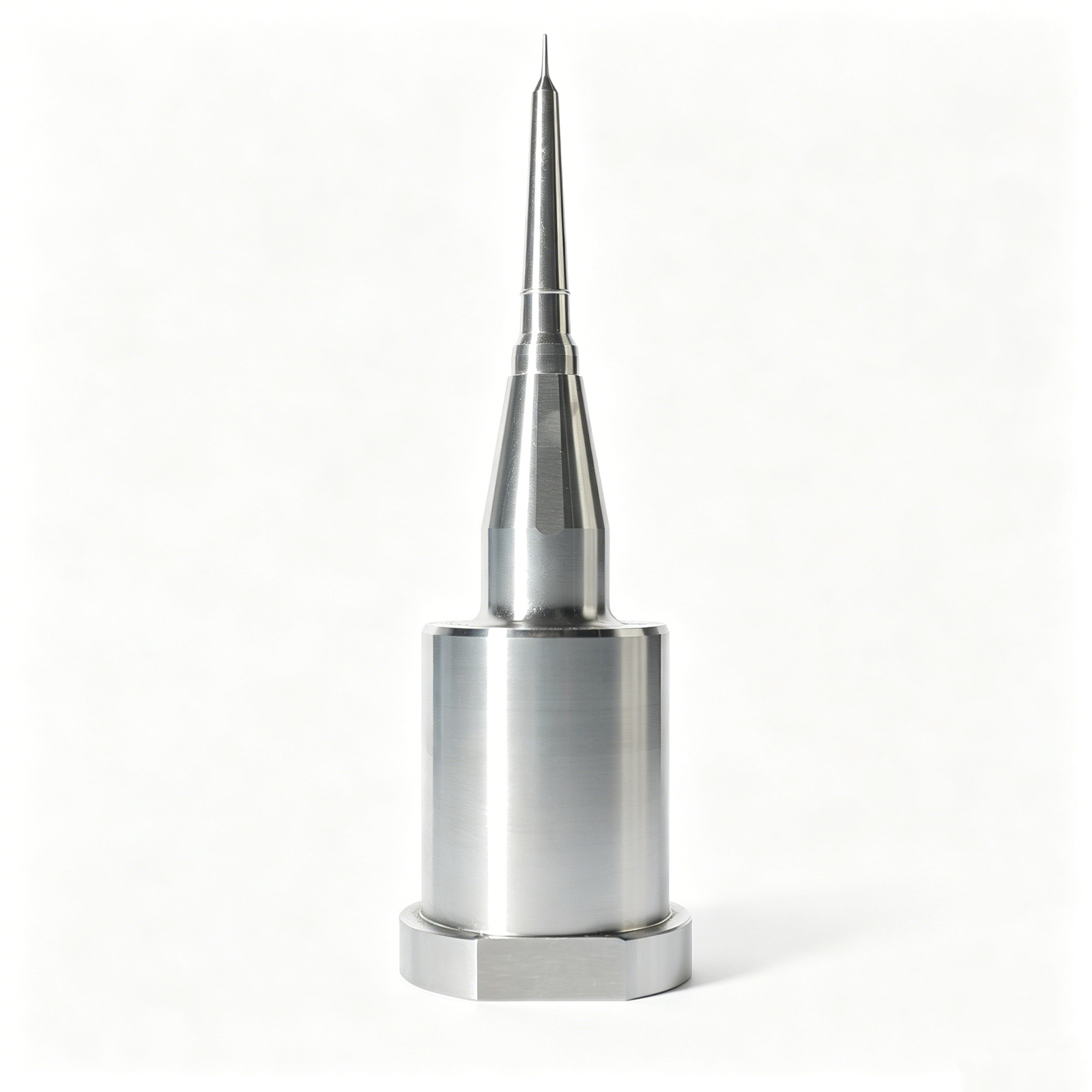


Related Configurable Component Families and Quotation





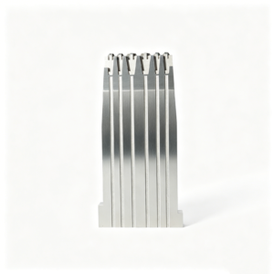
Why Teams Choose SUUXIANG for Custom CNC Machined Shafts
A drawing-driven workflow focused on manufacturability, critical features, controlled revisions, and inspection evidence.
Drawing-Led DFM Review
We review drawings, models, material requirements, and intended application context before aligning the quotation and proposed manufacturing route.
Process Route Planning
CNC turning, milling, EDM, grinding, and fitting are considered together where shaft geometry, access, finish, or sequencing requires it.
Critical Dimension Focus
Project discussions identify datums, functional fits, concentric features, surface requirements, and tolerance priorities so production decisions support assembly intent.
Revision Visibility
Drawing revisions, clarifications, and delivery information remain visible throughout the project, helping teams avoid manufacturing against superseded requirements.
Inspection Planning
Inspection methods and reporting expectations are discussed against the order requirements, with final documentation matched to the verified inspection plan.
Custom CNC Shafts and Related Component Families
Drawing-driven process routes for shafts, tooling components and related precision parts, reviewed against critical dimensions, materials, inspection requirements and delivery needs.
CNC Machining Services
Precision CNC machining services for custom shafts and related parts, planned from the drawing, material, critical dimensions and inspection requirements. Process selection may combine milling, turning, EDM, grinding and fitting where the geometry and tolerance strategy require it.
Upload a Drawing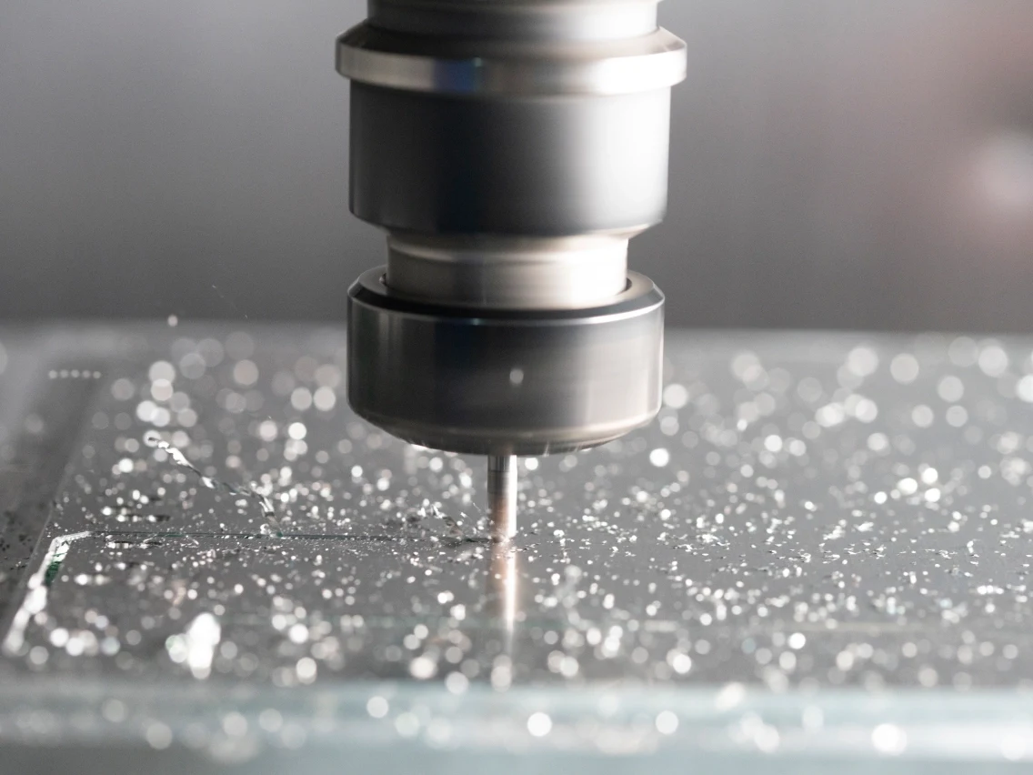
CNC Milling
Custom CNC milling services for shaft features such as flats, keyways, cross-holes, mounting faces and complex interfaces. Drawing review considers datum selection, cutter access, workholding and the relationship between milled features and turned diameters.
Upload a Drawing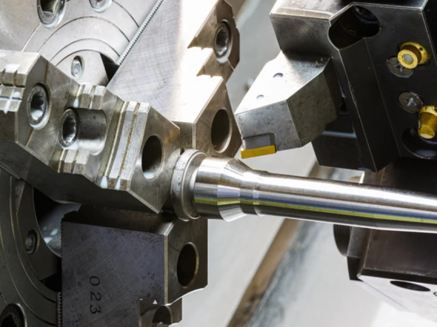
CNC Turning
Precision CNC turning services for rotational shaft geometries, including stepped diameters, shoulders, threads, grooves and bearing or sealing interfaces. Critical diameter, runout, surface and datum requirements should be identified before the machining route is committed.
Upload a Drawing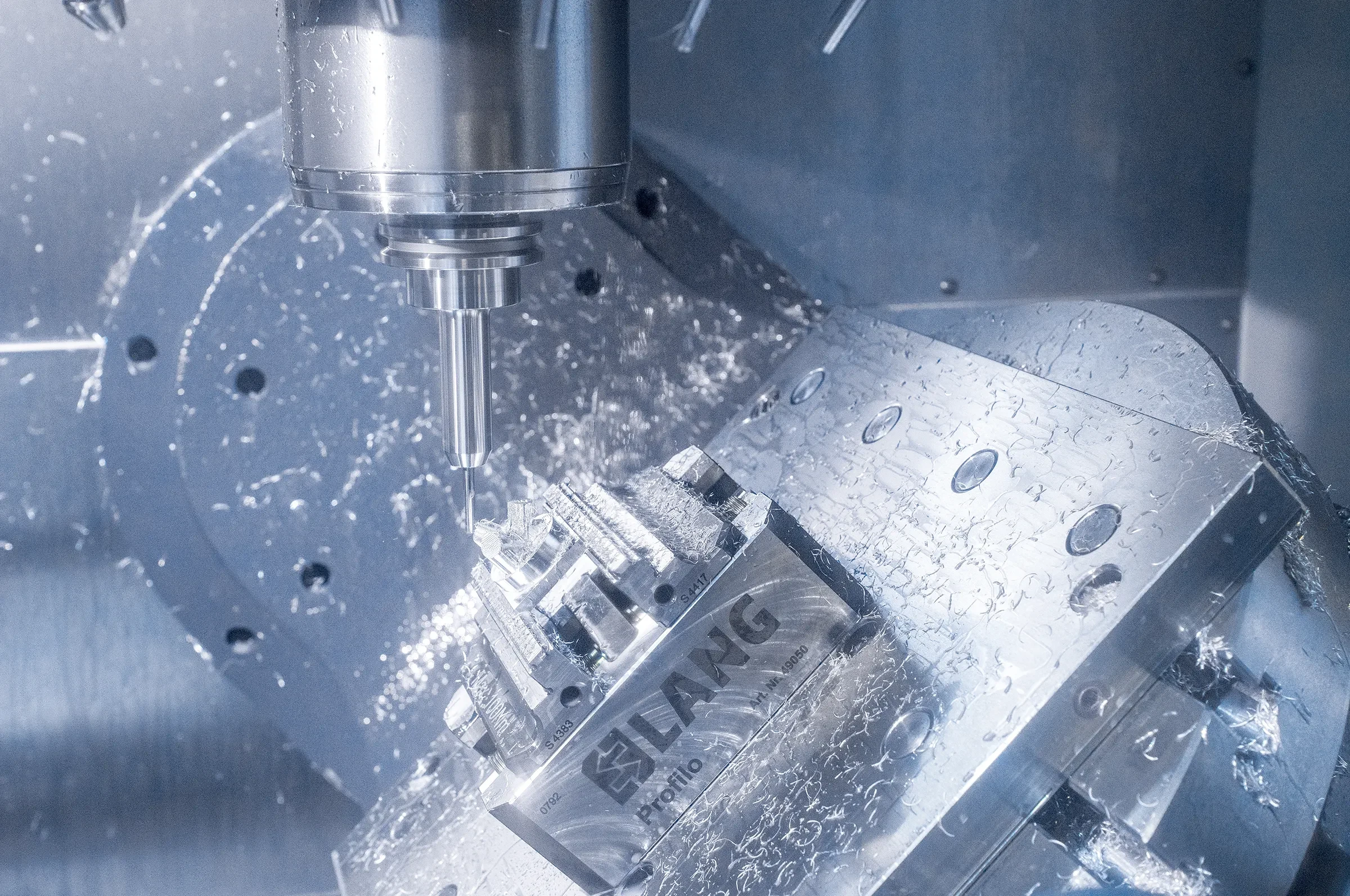
5-Axis Machining
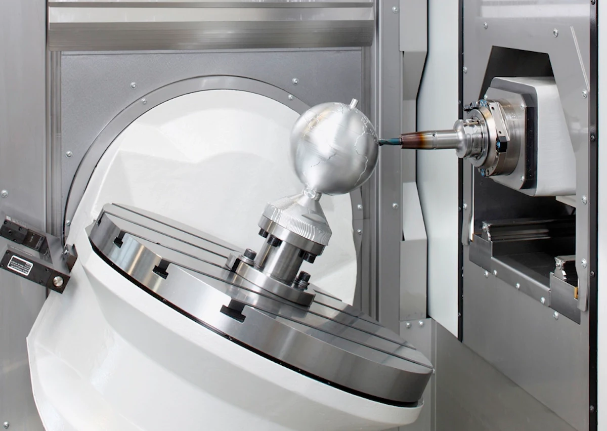
5-axis CNC machining supports shaft-adjacent features and complex components requiring multi-angle tool access. The review addresses fixture stability, reachable surfaces, datum transfer and whether five-axis positioning or continuous machining is appropriate for the specified geometry.
Upload a Drawing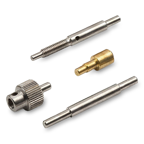
Swiss & Micro Machining
Swiss machining and micro machining support small, slender or detail-intensive shaft components where concentricity, feature access and handling require disciplined process planning. Suitability depends on part geometry, material, quantity, tolerances and verified production conditions.
Upload a Drawing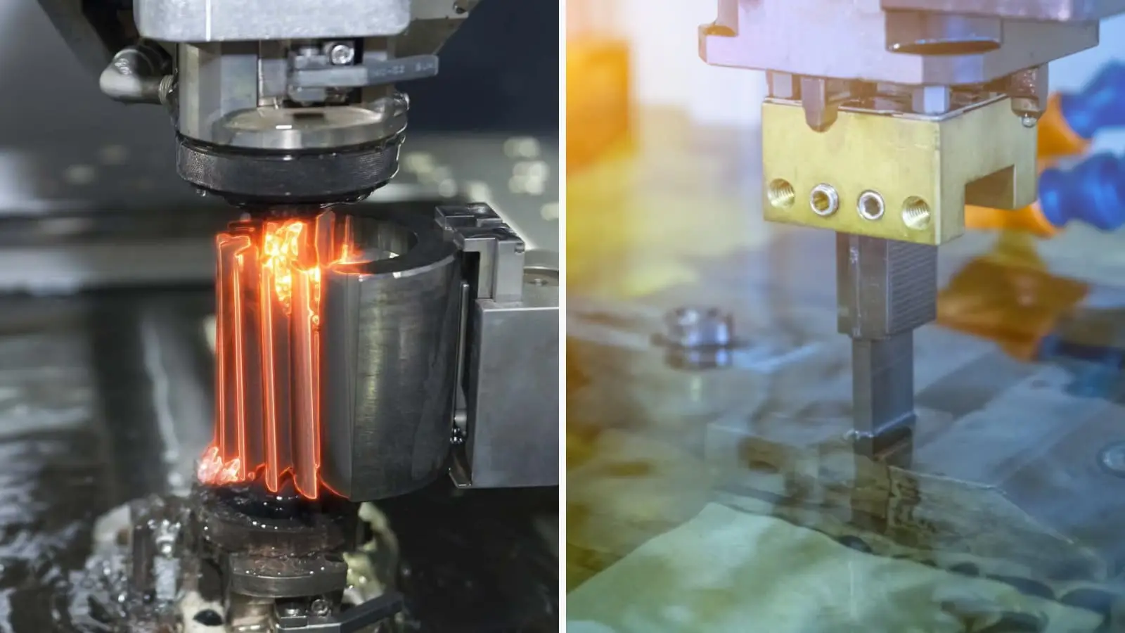
Wire & Sinker EDM
Wire EDM and sinker EDM services address hardened materials, narrow slots, internal profiles and features beyond conventional tool access. Electrode strategy, wire path, recast-layer considerations, finish requirements and downstream grinding needs are reviewed against the drawing.
Upload a Drawing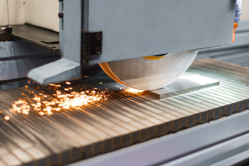
Precision Grinding
Precision surface and profile grinding is used where shaft diameters, flats, profiles or mating surfaces require controlled stock removal after machining or heat treatment. Grinding allowance, datum strategy, wheel access and inspection method should be defined before processing.
Upload a Drawing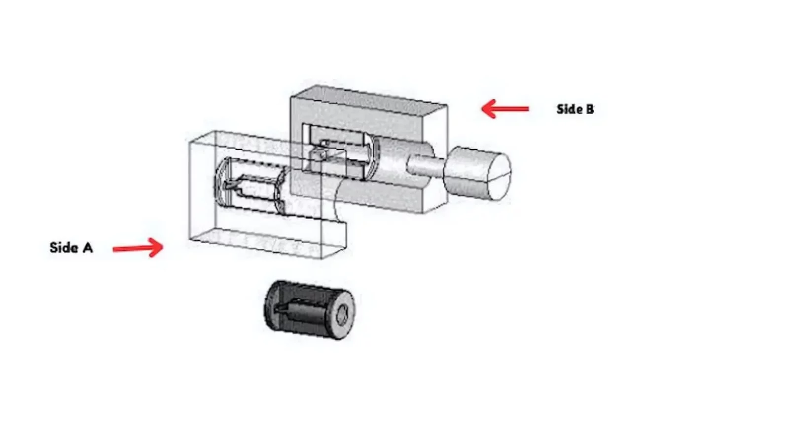
Mold Core & Cavity Inserts
Precision mold core and cavity inserts are manufactured from drawing-controlled geometry for molding applications. The process route may combine CNC machining, EDM, grinding and fitting, with attention to shutoff conditions, cooling interfaces, material condition and critical cavity features.
Upload a Drawing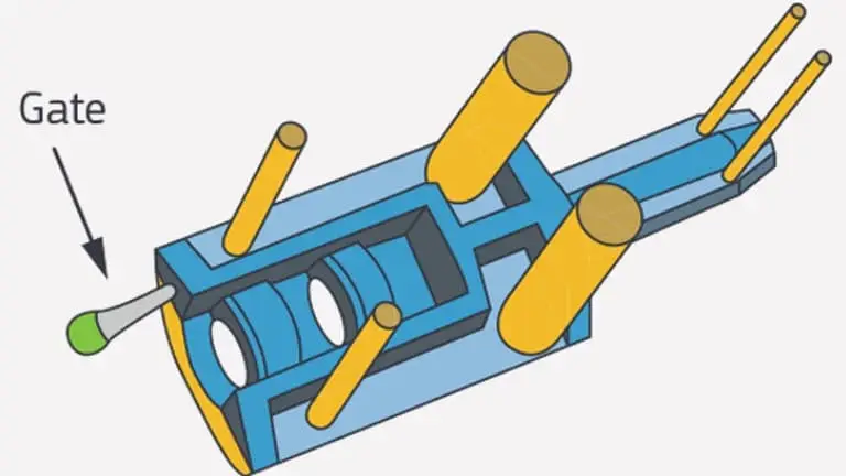
Ejector & Ejection Components
Ejector pins, sleeves and ejection components are configured to the mold design rather than treated as assumed stock items. Reviews focus on guidance, clearance, surface condition, heat treatment, mating parts and dimensions that affect ejection performance.
Upload a Drawing
Core Pins, Guide & Locating Components
Core pins, guide pins and locating components are produced to drawing-defined dimensions and mating requirements. Critical considerations include datum relationships, straightness, diameter control, hardness sequence, fit class and the inspection evidence required for assembly.
Upload a Drawing
Slides, Lifters, Gates & Mold Accessories
Mold slides, lifters, gates and accessories are manufactured as configurable mold-component families. Production planning considers movement interfaces, shutoffs, wear surfaces, angle relationships, machining access, EDM needs and fitting requirements with associated mold elements.
Upload a Drawing
Connector Mold Components
Precision connector mold components support connector-tooling geometries where pin layout, cavity detail, alignment and repeatable mating conditions are critical. The drawing review should identify functional datums, micro features, material condition and inspection priorities before quotation.
Upload a Drawing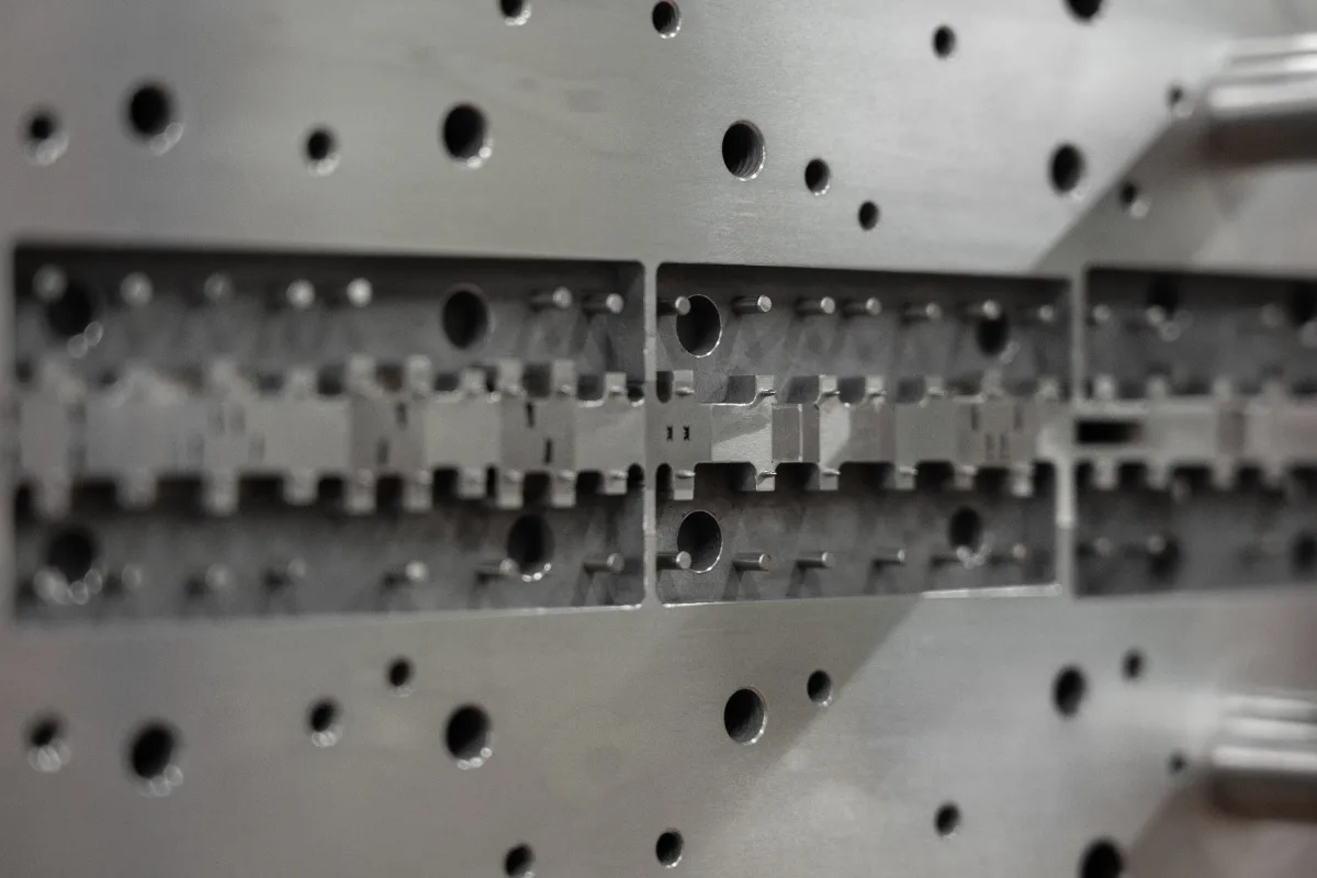
Stamping Die Components
Precision stamping die components are made for drawing-defined die assemblies, including punches, inserts, guide elements and forming-related parts. Material, heat-treatment sequence, EDM or grinding requirements, wear surfaces and mating dimensions guide the process plan.
Upload a Drawing
Injection, MIM, CIM & Overmolding Tooling
Injection, MIM, CIM and overmolding tooling components are supported when requirements fall within verified production scope. Reviews address cavity and core geometry, material behavior, tool access, ejection, gating, inserts and the dimensional requirements of mating components.
Upload a Drawing
Machining Materials
CNC machining materials are selected from the customer’s drawing and application requirements, with material grade, condition, traceability and post-machining treatment clarified before production. Material suitability depends on geometry, process route, functional demands and verified availability.
Upload a Drawing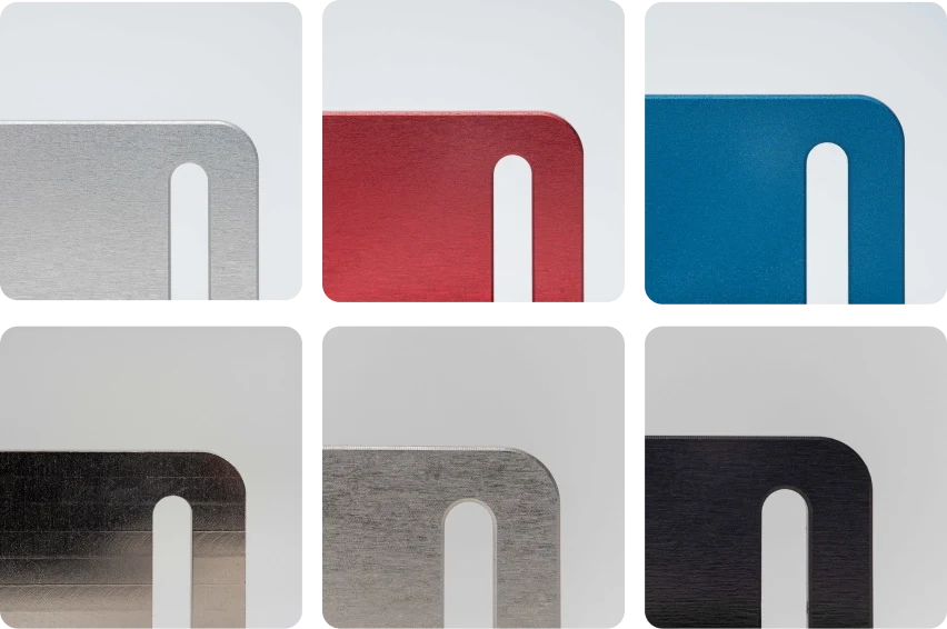
Surface Finishes & Heat Treatment
Surface finishing and heat treatment are planned around functional surfaces, corrosion or wear requirements, hardness sequence and dimensional change risk. Requirements should identify finish type, applicable areas, masking needs, hardness targets and any post-treatment grinding or inspection.
Upload a Drawing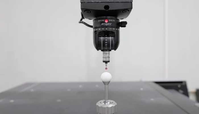
Quality, Metrology & Documentation
Precision inspection, metrology and quality documentation are aligned with the agreed drawing revision and inspection plan. Buyers should identify critical dimensions, measurement methods, reporting format, traceability needs and any first-article or final-inspection expectations with the RFQ.
Upload a Drawing
Prototyping & Low-Volume Production
Rapid prototyping and low-volume manufacturing support drawing-based development, validation and controlled production needs. Quantity, revision status, material, critical dimensions, surface requirements, delivery target and inspection scope should be supplied so the appropriate process route can be assessed.
Upload a DrawingMaterials for Custom CNC Machined Shafts
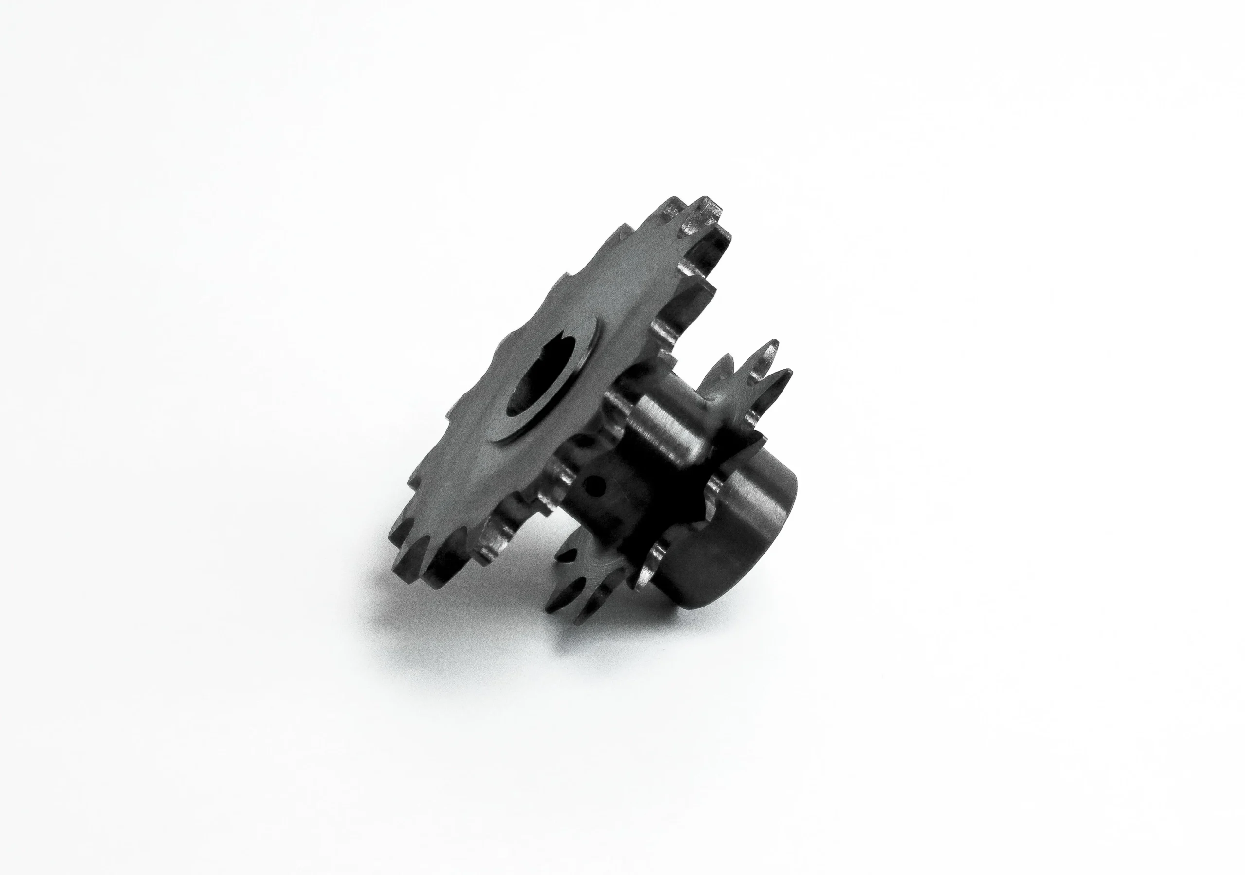
Carbon Steel
A practical choice for general-purpose custom cnc machined shafts where strength and cost control matter. Grade, heat-treatment condition, machining allowance, and corrosion-protection requirements should be defined on the drawing.
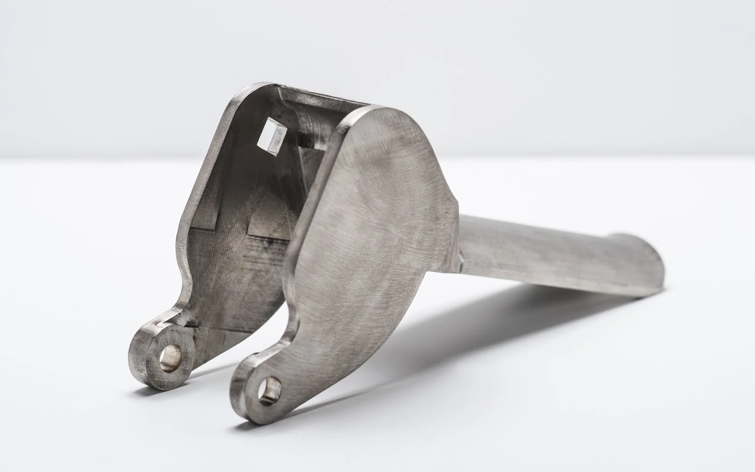
Alloy Steel
Used for shafts requiring a considered balance of strength, toughness, and wear performance. SUUXIANG reviews the specified alloy, heat-treatment sequence, grinding stock, and critical diameter requirements before selecting the process route.
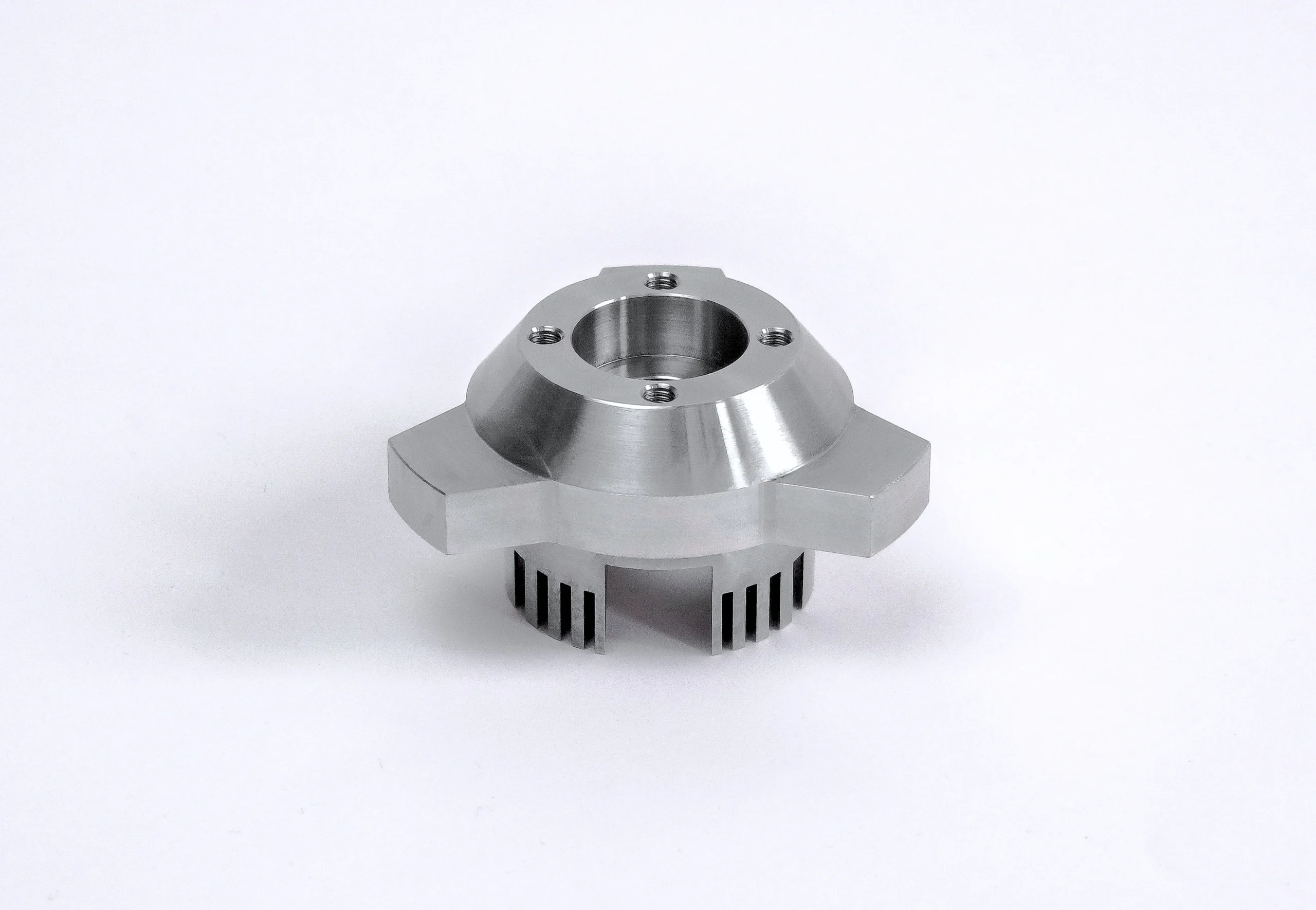
Stainless Steel
Suitable where corrosion resistance, cleanability, or environmental exposure affects shaft performance. Machinability varies by grade, so the drawing should identify material condition, surface finish, mating parts, and any passivation requirements.
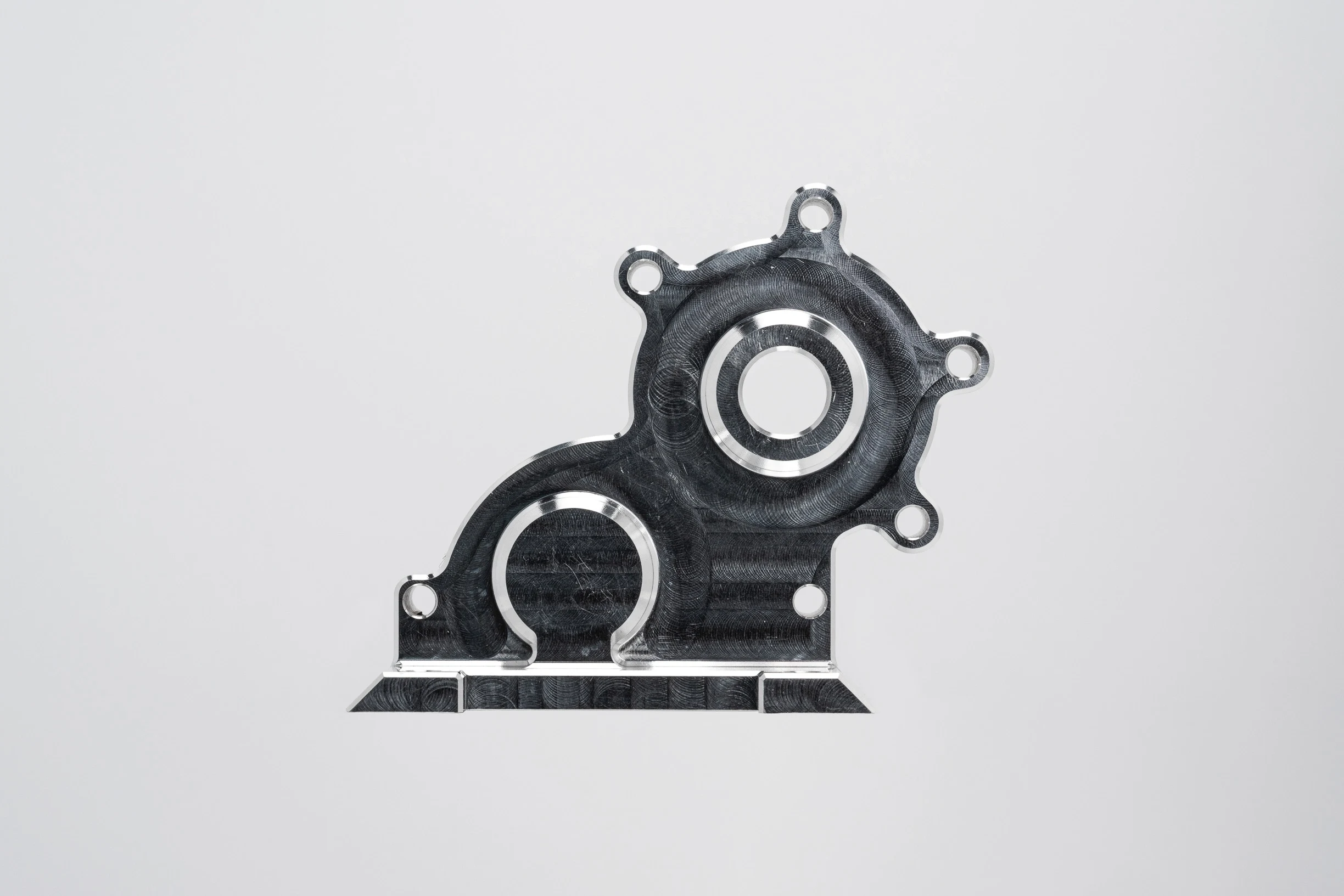
Aluminum Alloys
Often specified for lightweight shafts, fixtures, and motion-system components with lower mass requirements. Alloy choice, wall geometry, thread engagement, surface protection, and datum locations require review to support stable machining.
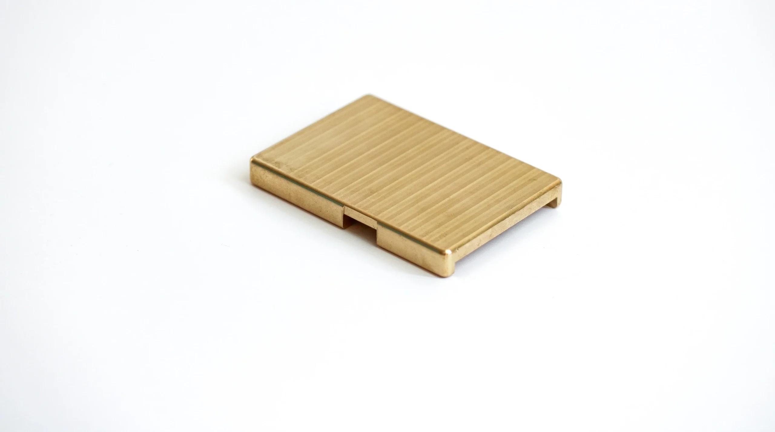
Brass Alloys
A machinable option for connector-related, electrical, and corrosion-conscious components. The material grade, functional conductivity needs, thread form, surface condition, and mating-interface requirements should accompany the RFQ.
Machining Processes for Custom CNC Machined Shafts
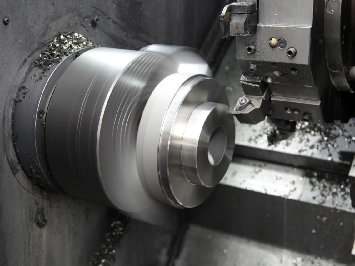
CNC Turning
CNC turning establishes shaft diameters, shoulders, tapers, threads and concentric cylindrical features from bar or prepared stock. The route is planned around datum control, clamping strategy and machining allowance for subsequent operations.
CNC Milling
CNC milling adds keyways, flats, slots, cross-holes and other non-round features that turning cannot complete alone. Tool access, feature orientation and the relationship to functional datums are reviewed before machining begins.
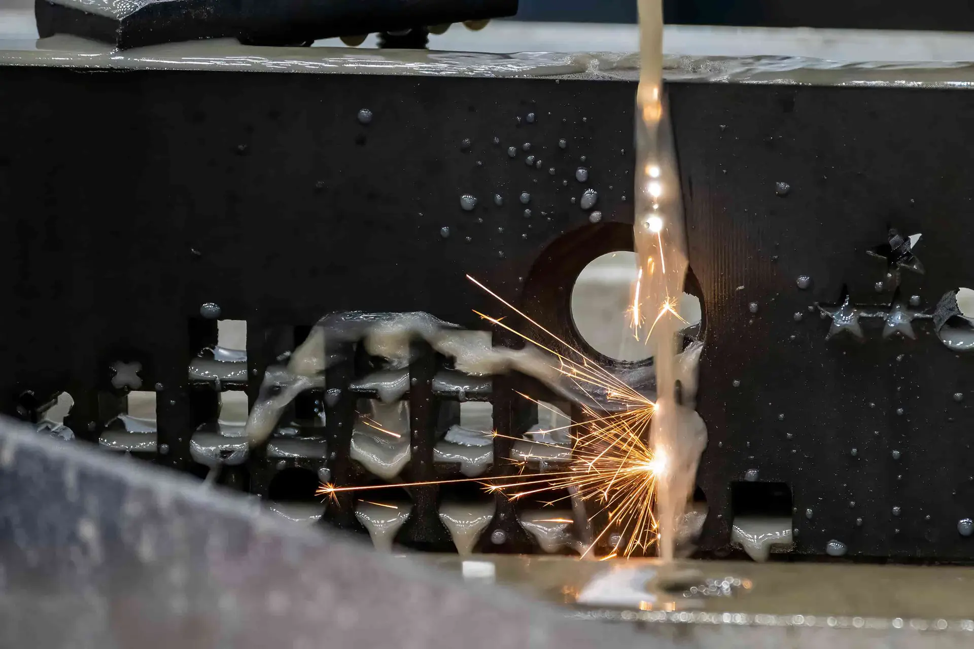
Wire EDM
Wire EDM can produce precise through-profiles, narrow slots and difficult-to-machine features where a wire path is suitable. SUUXIANG reviews material condition, start-hole requirements, wire access and downstream finishing needs for each application.

Precision Grinding
Precision grinding refines selected diameters, faces or bearing-related surfaces after the appropriate machining and heat-treatment sequence. Grinding stock, datum strategy, surface requirements and inspection methods should be defined during drawing review.
Fitting Inspection
Fitting and inspection confirm how custom CNC machined shafts relate to mating components and specified critical dimensions. The inspection plan is aligned with the order, drawing revision, required measurement evidence and delivery documentation.
Custom CNC Machined Shafts: Features and Finishing Options
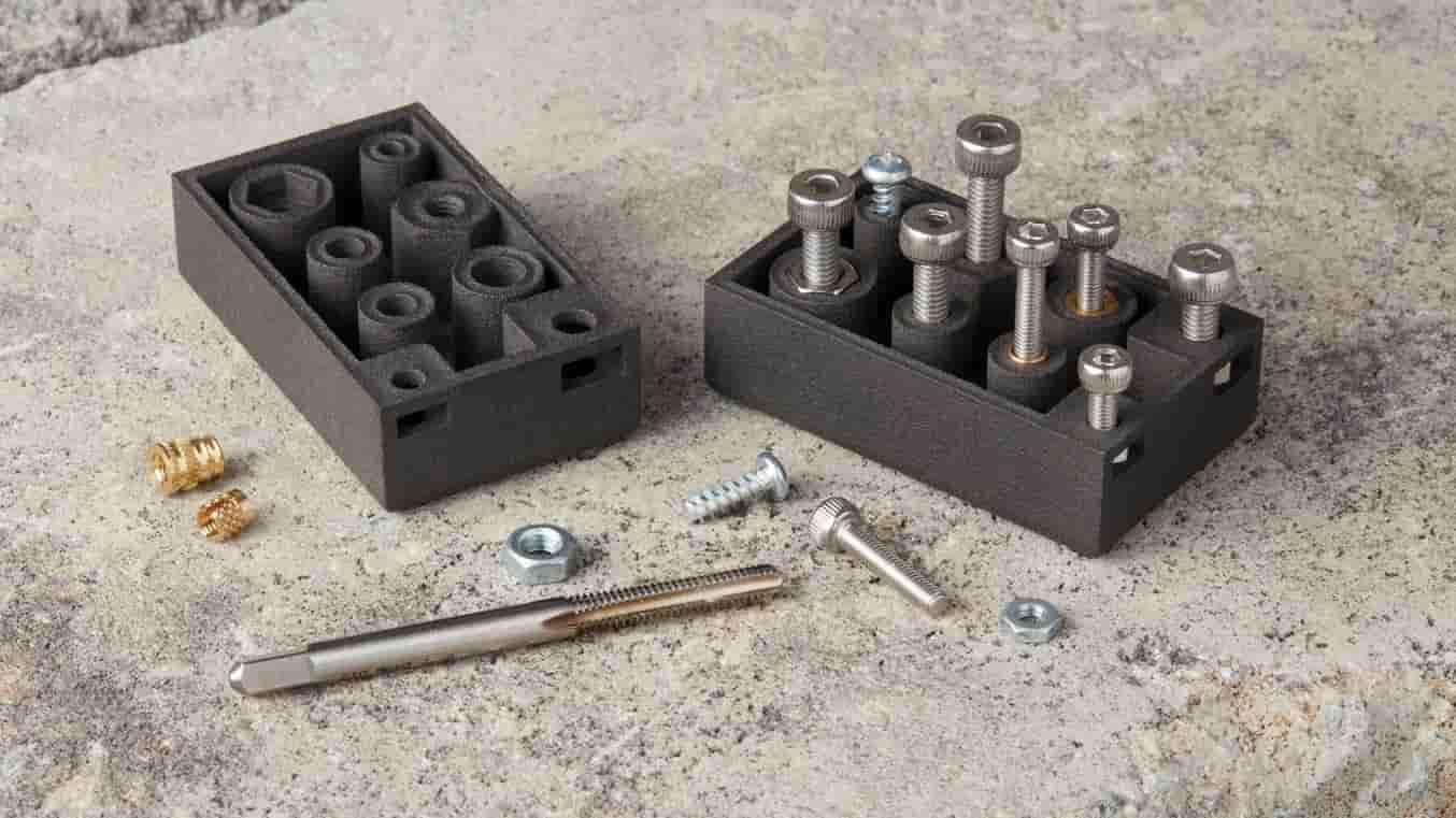
Threads and Knurls
External or internal threads, reliefs, and knurled grip areas can be specified with mating details, thread standard, engagement length, and surface condition to guide tool access and inspection planning.

Keyways and Flats
Milled keyways, drive flats, slots, and cross-holes support torque transfer, retention, or assembly orientation. Provide feature position from defined datums, corner requirements, and any mating-component constraints for review.

Splines and Profiles
Splines, lobes, and other drive profiles require clear geometry, functional fit criteria, and inspection expectations. SUUXIANG reviews whether milling, EDM, grinding, or a combined route best suits the specified profile.
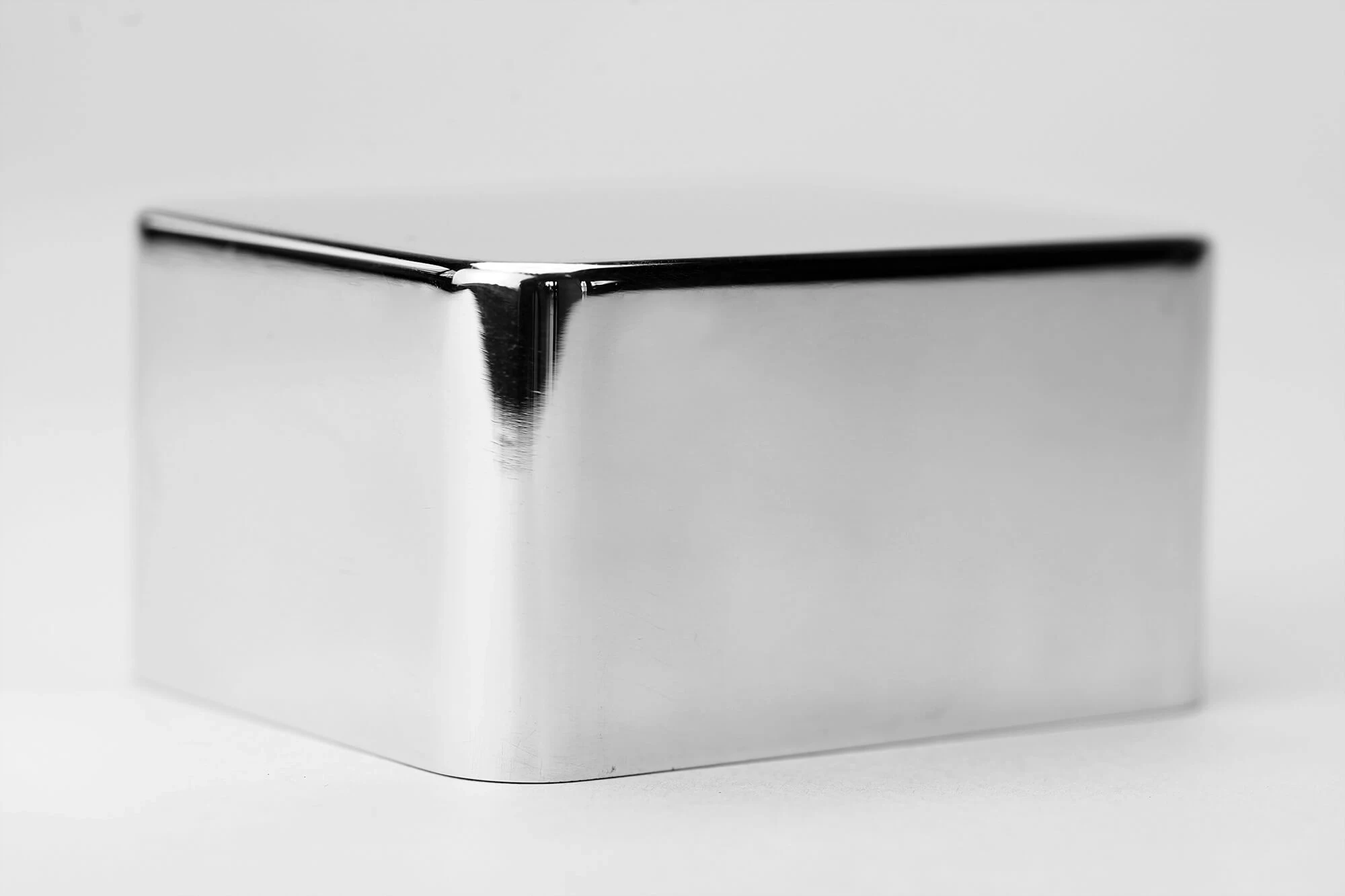
Surface Requirements
Specify roughness, coating or plating requirements, corrosion exposure, and surfaces that affect sealing, bearing contact, or sliding performance. These requirements help coordinate machining allowance, finishing sequence, and final measurement.

Heat Treatment Coordination
Hardening, tempering, nitriding, or other heat-treatment requirements should be reviewed with material and critical dimensions. The process plan can account for distortion risk, grinding stock, masking needs, and post-treatment verification.
About SUUXIANG Precision Manufacturing
SUUXIANG is the sole public-facing brand of Dongguan SuuXiang Precision Mold Co., Ltd., established in 2010 in Chang’an Town, Dongguan, Guangdong, China. Founded by and legally represented by XiaoCheng Huang, we help international engineering, sourcing, and quality teams convert drawings and specifications into inspected custom CNC machined shafts, precision mold components, connector tooling, and die components.
Our drawing-driven workflow brings together CNC milling and turning, multi-axis machining, EDM, precision grinding, fitting, and inspection. Before quotation or production commitments, we review material requirements, critical dimensions, datums, surface expectations, machining access, and the process sequence needed for the requested component.
What distinguishes SUUXIANG is disciplined project control rather than generic quoting. We keep DFM questions, revision information, inspection expectations, and delivery coordination visible throughout the work. Submit a 2D drawing, 3D model where available, quantity, material, quality requirements, and target date for a project-specific review.

Custom CNC Machined Shafts: From Drawing Review to Inspection
DFM and Datum Review
Before quoting custom CNC machined shafts, SUUXIANG reviews the drawing, model, functional interfaces, and critical dimensions. The discussion identifies datum logic, tolerance stack risks, tool access, material condition, and features that require a defined manufacturing sequence.
- Confirm functional datums and critical-to-quality dimensions
- Review keyways, threads, shoulders, grooves, and mating features
- Identify tolerance stack and machining-access risks
- Align material, heat treatment, quantity, and delivery requirements

Process Route Selection
Shaft geometry should determine the route, not a generic machining template. SUUXIANG plans the appropriate combination of CNC turning, milling, multi-axis work, EDM, and secondary operations according to profiles, internal features, access constraints, and specified surfaces.
- Use turning for primary diameters and rotational profiles
- Apply milling for flats, keyways, cross holes, and non-round features
- Assess wire EDM or sinker EDM where conventional tool access is limited
- Keep sequence decisions visible before production begins

Grinding and Fitting Strategy
Where journals, bearing seats, locating diameters, or interface surfaces need controlled final condition, the route must reserve suitable grinding stock and account for heat-treatment sequence. Fitting requirements are reviewed against the mating component and assembly function.
- Define which surfaces require post-machining grinding
- Preserve grinding allowance through earlier operations
- Review heat treatment before final-dimensional operations
- Clarify fit class, mating-part condition, and surface priorities
Inspection and Revision Control
Inspection planning follows the approved drawing and identified critical dimensions for each shaft project. SUUXIANG aligns measurement methods, reporting expectations, revision status, and delivery documentation so the supplied parts can be evaluated against the agreed production record.
- Link inspection points to critical dimensions and datums
- Agree required reports before production release
- Maintain drawing and revision visibility through the project
- Match final documentation to the verified inspection plan
Custom CNC Machined Shafts: A More Controlled Quoting Workflow
Compare project controls before committing custom shaft work to production.
← Swipe left or right to view →
Production Workflow for Custom CNC Machined Shafts
A controlled path from RFQ review through process planning, machining, inspection, and delivery coordination.
Review Drawing and RFQ
We review drawings, models, material, quantity, critical dimensions, datum strategy, surface requirements, inspection needs, and delivery targets before confirming a feasible process route.
Plan Material and Process
The team aligns material and heat-treatment requirements with turning, milling, EDM, grinding, fitting, and inspection steps, identifying machining allowances and feature-access risks early.
Machine Critical Shaft Features
CNC turning establishes shaft profiles, while milling or multi-axis operations create specified flats, cross holes, keyways, threads, or other drawing-defined features.
Apply EDM and Grinding
Where geometry or finish requires it, wire EDM, sinker EDM, and precision grinding are planned around heat treatment, electrode strategy, wire paths, and grinding stock.
Inspect, Pack, and Coordinate
Finished parts are checked against the agreed inspection plan, documented as required, protected for shipment, and coordinated with visible revision and delivery information.
How to Work With SUUXIANG
Submit complete requirements early so the process route, critical dimensions, inspection plan and delivery expectations can be reviewed before production begins.
Submit Your Drawing Package
Provide 2D drawings, available 3D models, material, quantity, application context, target delivery date, and dimensional, surface, heat-treatment, and documentation requirements.
Confirm Critical Requirements
Review datums, critical dimensions, tolerance stack, surface priorities, machining access, concentricity needs, and any mating-component information that affects the process route.
Review DFM and Quotation
Evaluate the proposed manufacturing approach, including turning, milling, EDM, grinding, fitting, inspection scope, revision status, commercial terms, and any identified manufacturability risks.
Approve Production or Sampling
Confirm the agreed drawing revision, requirements, and quotation before SUUXIANG schedules custom CNC machined shafts for sampling or production through the verified process plan.
Receive Parts and Records
Receive completed parts with documentation aligned to the order and verified inspection plan, supported by visible revision control and delivery coordination.
Custom CNC Machined Shafts: Certification and Quality Documentation
Approved Customer Cases for Custom CNC Machined Shafts
Reserved for an approved customer case study. This card will document the drawing scope, critical dimensions, inspection evidence, and verified project outcome after customer permission is confirmed.
Reserved for approved customer feedback. A published testimonial will include only a customer-authorized quote and verified information about the production, quality, or delivery outcome.
Reserved for an approved sourcing or engineering case. This card will be completed with traceable customer evidence, including applicable revision-control, inspection, and component-performance results.
Custom CNC Machined Shafts FAQ
Project-dependent answers for engineers and sourcing teams preparing a drawing-based shaft RFQ.
What is the MOQ for custom CNC machined shafts?
Can I order a sample of custom CNC machined shafts before production?
What lead time should I expect for custom CNC machined shafts?
Which materials can SUUXIANG review for a shaft RFQ?
What tolerances can you hold on CNC-machined shafts?
What inspection evidence can be provided with a shaft order?
How are payment terms set for a custom shaft machining order?
Can SUUXIANG arrange international shipping for shaft parts?
How do you handle drawings and IP for a custom machining RFQ?
The Complete Buyer’s Guide to custom cnc machined shafts
Use this decision framework to specify shaft geometry, materials, tolerances, finishing, inspection, and supplier controls—while avoiding drawing, cost, and qualification mistakes that can delay a drawing-based CNC program.
1. What Are custom cnc machined shafts?
1 drawing-specific shaft is a rotational component defined by its diameters, shoulders, datums, features, and functional interfaces. It may transmit motion or torque, locate a mating part, or support an assembly; custom cnc machined shafts are made to that controlled definition rather than selected from a standard size.
2 commodity bar stock and catalog shafts supply a starting diameter or standardized geometry, but they do not inherently resolve bearing seats, keyways, threads, cross-holes, runout relationships, or assembly-specific lengths. The drawing must state which surfaces are functional and how features relate to the datum scheme.
3 CNC turning commonly establishes the concentric outer geometry, then milling, drilling, tapping or threading, grinding, and other secondary operations create functional details. This combined-process context is consistent with the shaft operations described by FZE Manufacturing at https://fzemanufacturing.com/capabilities/shaft-machining-services; the final route should be chosen from the part drawing, material condition, and inspection requirements.
2. How Shaft Machining Evolved
1949 marked the start of numerical-control development at MIT, shifting machine motion from manual skill and fixed templates toward programmed coordinates. Earlier shaft production centered on manual turning and standardized diameters, so geometry changes often meant new setups, gauges, and operator-dependent adjustment.
By the 1970s, CNC controls made repeatable turning programs practical for production parts, while live tooling added cross-drilled holes, flats, threads, and keyway-related operations without moving a part through as many separate setups. Modern shaft work may combine turning, milling, drilling, tapping, and spline or keyway cutting when the drawing requires interface features (https://fzemanufacturing.com/capabilities/shaft-machining-services).
Today, low-volume custom cnc machined shafts are commonly managed as controlled drawing revisions rather than merely modified stock sizes. The useful evidence is the link between drawing datums, programmed features, inspection results, material records, and the delivered revision—not an assumed capability based on a machine label.
3. Types of custom cnc machined shafts
Shaft form should follow the torque path, supported component, assembly method, and datum scheme on the drawing. Custom cnc machined shafts often combine turned diameters with non-round interfaces that require separate operations.
Solid Shafts
Solid shafts carry torque through a continuous section and commonly mate with bearings, hubs, or couplings. CNC turning establishes journals; greater stiffness trades against material weight and cycle time.
Hollow Shafts

Hollow shafts reduce rotating mass and may carry fluid, wiring, or a central fastener. Drilling or boring follows turning; wall thickness must balance weight reduction against torsional rigidity and machining access.
Stepped And Tapered Shafts

Stepped diameters locate bearings, seals, and gears, while tapers provide self-centering contact. Turning creates both forms; shoulders and taper runout need datum-controlled inspection, with more interfaces increasing setup complexity.
Threaded And Keyed Shafts
Threaded ends retain nuts or collars, and keyways transmit torque to a hub or pulley. Turning cuts threads, but keyways normally need secondary milling, broaching, or EDM; keys simplify service yet introduce stress concentrations.
Splined And Gear Interfaces
Splines and gear-interface forms distribute torque across multiple teeth and mate with corresponding hubs or gears. Hobbing, broaching, shaping, milling, or wire EDM may be needed after turning; tooth accuracy raises cost but improves load sharing.
4. Materials for custom cnc machined shafts
For custom cnc machined shafts, choose material from load, environment, mass, and mating-part requirements. Forster Tool documents a general shaft-material range from titanium to plastic: https://www.forstertool.com/products/custom-shaft-manufacturing.
| Material family | Advantages | Limitations | Typical shaft use | Specify |
|---|---|---|---|---|
| Steel | Strong; heat-treatable | Corrosion risk | Drive shafts | Grade; hardness |
| Stainless | Corrosion resistant | Higher cost | Wet environments | Alloy; medium |
| Aluminum | Light; machinable | Lower wear | Weight-sensitive shafts | Temper; bearing load |
| Brass/copper | Machinable; conductive | Soft | Electrical shafts | Alloy; conductivity |
| Titanium | Light; corrosion resistant | Costly machining | Specialized shafts | Grade; finish |
| Plastic | Insulating; light | Creep | Low-load shafts | Polymer; temperature |
Carbon And Alloy Steels
1045 and 4140 favor strength, wear resistance, and heat treatment for drive or locating shafts.
Stainless Steels
303 and 316 trade higher cost for corrosion resistance; specify the service medium and required hardness.
Aluminum Alloys
6061-T6 reduces mass and machines readily, but wear surfaces need careful mating design.
Brass And Copper Alloys
C360 machines cleanly for low-load, conductive shafts; copper alloys are comparatively soft.
Titanium
Ti-6Al-4V combines low weight and corrosion resistance, with slower machining and higher cost.
Engineering Plastics
PEEK or acetal can suit insulating, low-load shafts; confirm temperature, creep, and moisture exposure.
5. Custom Features and Surface Finishes
One shaft drawing should identify every functional diameter, datum, and mating condition before machining begins. SUUXIANG reviews feature sequence, tool access, and finishing allowance against the application requirements.
| Option | Primary Purpose | Drawing Note |
|---|---|---|
| Grinding | Size and texture control | State final roughness and diameter |
| Passivation | Corrosion support | Identify material and post-process condition |
| Plating or coating | Wear or appearance | Specify final-size allowance and masked areas |
Functional Geometry
Two or more diameter steps need clear shoulder radii and datum references; these features establish bearing, seal, gear, or collar locations.
One drawing can combine grooves, retaining-ring seats, threads, cross holes, flats, keyways, or splines, but specify their positional relationship to the primary axis.
- Dimension groove width and corner condition.
- Define thread standard, class, and engagement.
- Show mating-part interfaces and assembly clearance.
Finish Selection
Three finish questions govern selection: required roughness, corrosion exposure, and wear mechanism. Grinding or polishing may support functional surfaces; passivation, plating, anodizing, black oxide, or coatings require project-specific verification.
Allowance After Finishing
A plated or coated diameter changes after treatment, so define whether the stated size applies before or after finish. SUUXIANG should confirm the process route, masking needs, and inspection basis during drawing review.
6. Quality Controls for custom cnc machined shafts
Two functional questions govern shaft acceptance: what feature locates the mating part, and what axis rotates. For custom cnc machined shafts, the drawing should assign datums and inspection methods to those functions before release.
Datums And Diameter Control
One bearing seat may need a tighter diameter tolerance than a non-mating journal. Define the datum axis from the functional diameter, not an arbitrary turned surface.
Two-point micrometer checks suit accessible diameters; a bore gauge or functional mating gauge may better represent fit. Record the measurement location when taper or local wear matters.
Rotational Geometry
One common datum axis should govern concentricity, total runout, and related features such as shoulders, threads, or keyways. Indicate whether runout is checked between centers, in a chuck, or on the actual bearing journals.
Two geometry checks answer different risks: straightness controls a bent axis, while cylindricity controls the whole diameter form. A dial indicator, V-block setup, or CMM should be selected against the specified datum scheme.
Surface And Feature Verification
One surface requirement should identify roughness direction and measurement cutoff when it affects seals, bearings, or sliding fits. Thread pitch, keyway width, edge breaks, and burr limits need feature-specific gauges or visual criteria.
Three buyer-requested controls are first-article review, in-process checks, and final inspection. Request material documentation, report format, sampling scope, and revision identification in the RFQ; these controls must be agreed for the order.
7. Choosing a Shaft Machining Manufacturer
2 supplier reviews should separate demonstrated shaft experience from a generic machine list. Ask for evidence tied to the drawing’s datums, functional interfaces, and planned inspection route before awarding work.
Experience And Process Fit
FZE identifies turning, milling, drilling, keyways, and threading as shaft operations (https://fzemanufacturing.com/capabilities/shaft-machining-services). Ask suppliers which operations, workholding, and secondary processes apply to your geometry.
1 comparable part sample should show feature sequence, not another customer’s confidential drawing. Request examples matching shaft length-to-diameter ratio, threads, keyways, and runout-critical features.
DFM, Material, And Measurement
2D drawings should prompt a written DFM response covering datum interpretation, tool access, machining allowance, heat-treatment sequence, and risk items. Ask what revision-controlled questions must close before setup.
1 material requirement needs a defined purchasing and traceability path. Confirm material documentation, inspection methods for critical dimensions, report format, and nonconformance disposition.
Transfer And Delivery Control
1 prototype approval should establish the transferable process record: program revision, first-article criteria, inspection plan, packaging, and change-control owner. Ask how production changes are communicated and reapproved.
3 logistics questions matter: What is the committed ship date? How are finished shafts protected from damage and corrosion? Which shipment documents accompany the order?
8. Common Shaft Sourcing Mistakes
Two controls prevent most shaft RFQ escapes: a complete drawing package and a measurable acceptance plan. Purchasing should require both before comparing quotations for custom cnc machined shafts.
Define The Drawing Basis
Three missing items—datums, surface-finish callouts, and heat-treatment requirements—force assumptions that can misalign bearing seats or change post-treatment size. Identify functional datums, Ra requirements, treatment sequence, and finish stock on the released drawing.
Control Relationships And Tolerances
One tight diameter tolerance does not control runout between journals, shoulders, and mating features. Specify the datum-referenced runout requirement and apply tight tolerances only where function needs them; unnecessary limits raise grinding, inspection, and rejection cost.
Verify Material And Acceptance
Two common shortcuts—selecting material by habit and approving a sample by appearance—can produce inadequate strength, corrosion resistance, or assembly performance. State the material grade, required condition, inspection report, and functional checks such as fit, rotation, torque, or mating-part verification.
9. Launching a Custom Shaft Program
One controlled launch turns a drawing into a traceable production baseline for custom cnc machined shafts. SUUXIANG should confirm evidence and approvals before material is committed or batches are released.
Capture Released Requirements
1 released 2D drawing should define dimensions, datums, tolerances, material, heat treatment, finish, and inspection priorities.
1 3D model helps clarify geometry; include annual volume, target dates, mating-part interfaces, packaging needs, and any functional context.
Review DFM And Quotations
1 DFM review should identify tool access, workholding, slender-shaft support, process sequence, grinding stock, and feasible inspection methods.
2 quotations should be compared by stated assumptions, process route, included documentation, lead-time basis, and revision level—not price alone.
Approve And Control Production
1 prototype approval should record the accepted drawing revision, deviations, measurement results, and disposition before a first article.
1 first-article acceptance should precede pilot production; batch release requires documented approval, traceable records, and controlled change notices.
10. custom cnc machined shafts Pricing
Four pricing patterns help buyers separate one-time launch effort from repeat-part economics. The comparison is illustrative: it supports RFQ planning, not a SUUXIANG price or delivery commitment.
Eight quote inputs determine the final cost: geometry, material, tolerance, secondary operations, finishing, inspection, packaging, and order volume. For custom cnc machined shafts, include the controlled drawing revision, 3D model when available, critical datums, required reports, and target date so the process route can be reviewed before quotation.
| Order scenario | Setup/tooling intensity | Unit-cost trend | Typical lead-time factors | Best fit |
|---|---|---|---|---|
| 1–5 prototype parts | High per part | Highest | Programming, material release, first-piece inspection | Design verification |
| 6–50 bridge parts | Moderate | Declines as setup spreads | Fixture reuse, secondary operations, inspection scope | Pilot build or service spares |
| 51+ repeat parts | Lower per part after validation | Lowest when the route is stable | Material planning, batch size, packaging, approved revision | Recurring controlled demand |
Review Your Custom CNC Machined Shafts Drawing
Send your 2D drawing, 3D model when available, material, quantity, quality requirements, and target delivery date for a focused project review.