
CNC Parts for Electronics Assembly Nests, From Your Drawings
SUUXIANG reviews critical dimensions, datum strategy, and process routes for CNC parts for electronics assembly nests before quotation and production planning.
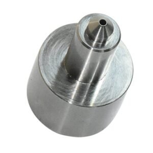
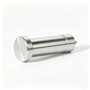
Representative Assembly-Nest Tooling and Related Components





Related Configurable Families and RFQ Options




CNC Parts for Electronics Assembly Nests: Engineering Advantages
Drawing-driven review focuses on the interfaces, process choices, and inspection evidence that influence repeatable nest fit.
Datum-First Review
We review locating surfaces, mating interfaces, and datum relationships before routing work, helping align nest geometry with the intended electronics assembly sequence.
Critical Feature Focus
Critical dimensions, positional relationships, and surface requirements are identified early so machining and inspection attention follows functional fit priorities.
Practical Process Routing
CNC machining, EDM, grinding, and fitting are considered together, with access, wire paths, electrode needs, and machining allowance discussed against the drawing.
Revision Visibility
Drawing revisions, open questions, and agreed manufacturing assumptions remain visible through project coordination, reducing ambiguity between quotation, production, and inspection.
Inspection Planning
Inspection methods and reporting needs are defined around critical nest features, supporting traceable acceptance evidence that matches the verified order requirements.
CNC Parts for Assembly Nests and Tooling
Drawing-driven process routes for configurable precision parts, mold components, connector tooling and die components, reviewed against critical dimensions, materials and inspection requirements.

CNC Machining Services
Precision CNC machining services translate drawings and models into custom parts through planned milling, turning, EDM, grinding and inspection. RFQ review addresses material, datums, critical dimensions, surface requirements, quantity and delivery expectations before a production route is confirmed.
Upload a Drawing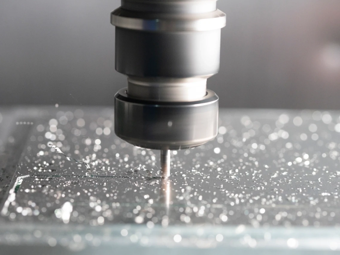
CNC Milling
Custom CNC milling services support prismatic parts, assembly nests, fixtures, mold inserts and tooling plates. Tool access, clamping strategy, feature depth, internal corners and tolerance relationships are reviewed to establish a practical machining sequence and inspection approach.
Upload a Drawing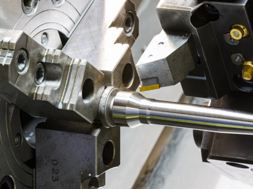
CNC Turning
Precision CNC turning services produce rotational and threaded components such as pins, bushings, sleeves, shafts and locating features. Diameter relationships, runout, thread requirements, material condition and subsequent grinding or EDM needs should be defined from the drawing.
Upload a Drawing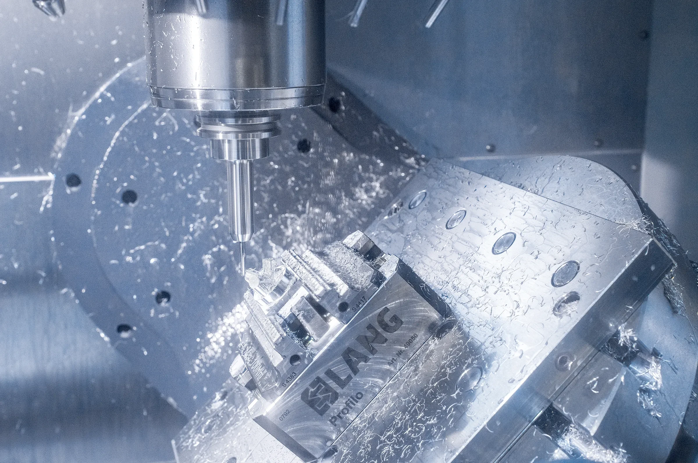
5-Axis Machining
5-axis CNC machining supports complex angled features, contoured surfaces and multi-face parts where fewer setups can protect datum relationships. Part geometry, tool reach, workholding, collision risk and inspection access are evaluated before selecting the machining strategy.
Upload a Drawing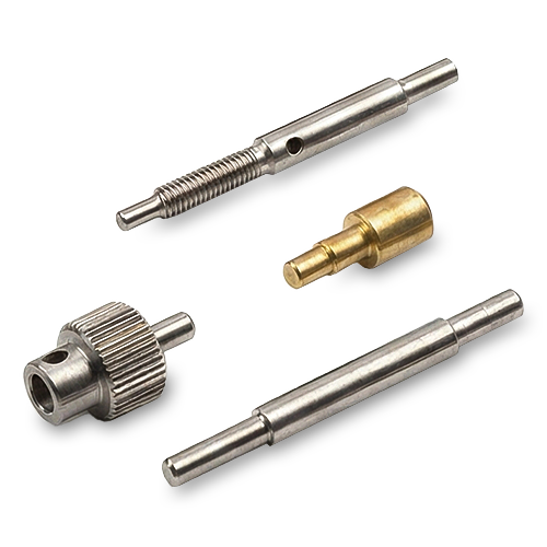
Swiss & Micro Machining
Swiss machining and micro machining support small, slender and detail-intensive components where concentricity, feature handling and burr control matter. Review should consider material, minimum features, tolerances, surface needs, quantity and inspection method before production planning.
Upload a Drawing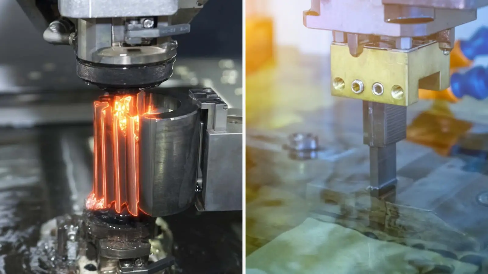
Wire & Sinker EDM
Wire EDM and sinker EDM services address hardened materials, narrow slots, sharp internal geometry, deep ribs and features beyond conventional tool access. The process plan considers wire path or electrode strategy, flushing, recast-layer requirements, allowances and finishing needs.
Upload a Drawing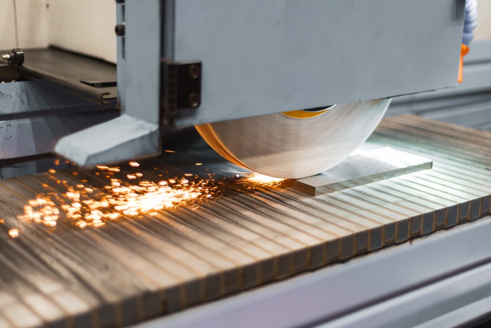
Precision Grinding
Precision surface and profile grinding brings controlled flatness, parallelism, profile and size to critical tooling surfaces. Grinding stock, heat-treatment condition, datum sequence, wheel access and measurement method should be agreed before final finishing.
Upload a Drawing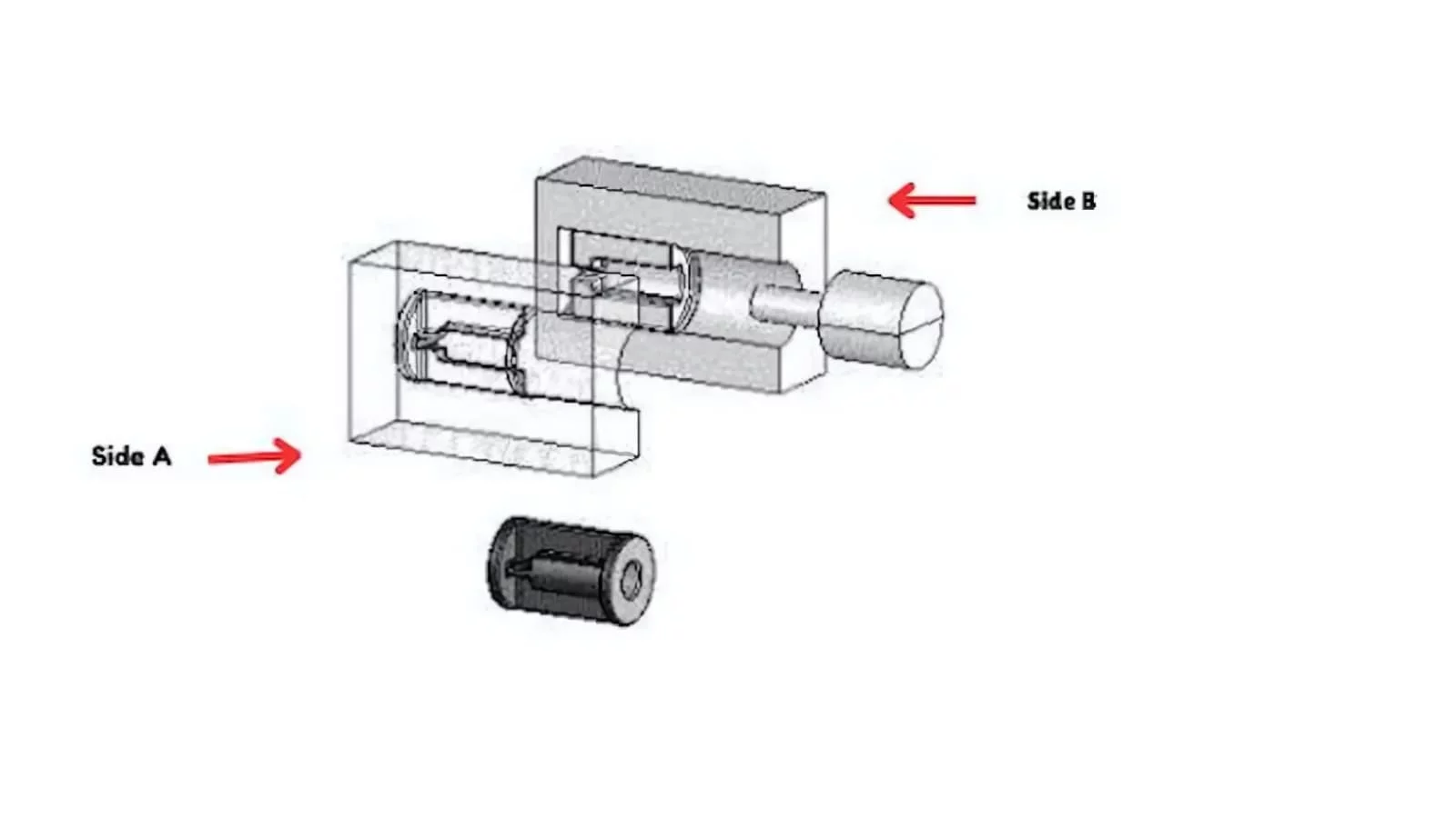
Mold Core & Cavity Inserts
Precision mold core and cavity inserts are configured from the molding geometry, material specification and critical forming surfaces. Machining, EDM, grinding, fitting and inspection are planned around datum control, cooling or vent details, heat treatment and required interface relationships.
Upload a Drawing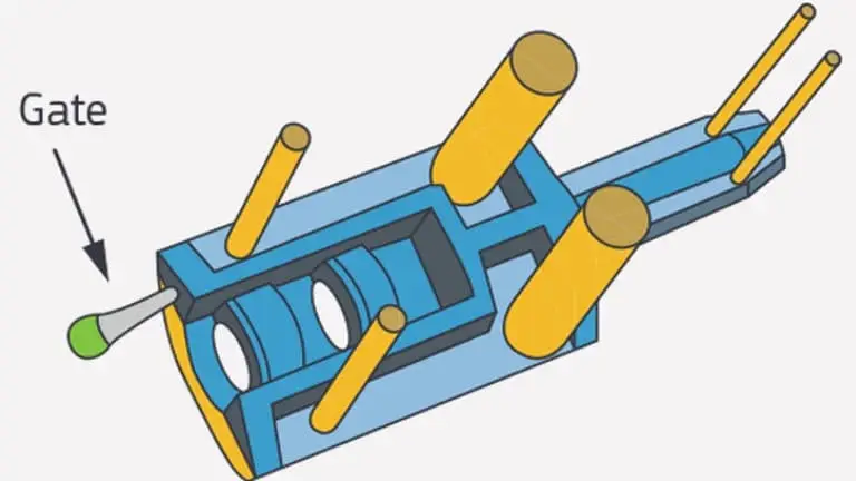
Ejector & Ejection Components
Ejector pins, sleeves and ejection components are made to drawing-defined dimensions and mating requirements for reliable mold movement. Diameter, clearance, hardness, surface condition, pin geometry and fit with plates or molded features require coordinated review.
Upload a Drawing
Core Pins, Guide & Locating Components
Core pins, guide pins and locating components establish repeatable mold alignment and feature position. Manufacturing planning focuses on diameter and length control, mating fits, concentricity, wear conditions, material treatment and inspection points identified by the assembly drawing.
Upload a Drawing
Slides, Lifters, Gates & Mold Accessories
Mold slides, lifters, gates and accessories are configurable tooling elements requiring attention to travel, interface geometry, wear surfaces and molding-function details. Process selection may combine CNC machining, EDM, grinding and fitting according to the verified design requirements.
Upload a Drawing
Connector Mold Components
Precision connector mold components support fine-pitch and mating-feature tooling where positional accuracy and repeatable datum control are central. Drawing review considers pin or cavity geometry, insert relationships, EDM access, material condition, surface requirements and inspection evidence.
Upload a Drawing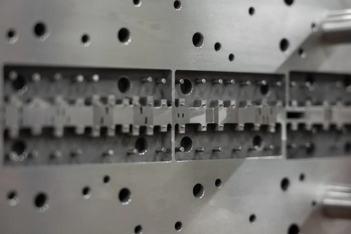
Stamping Die Components
Precision stamping die components include punches, dies, guide elements, inserts and custom wear parts made to the required die relationship. Clearance, profile, hardness, grinding stock, EDM strategy and fit-up requirements guide the manufacturing and inspection plan.
Upload a Drawing
Injection, MIM, CIM & Overmolding Tooling
Injection, MIM, CIM and overmolding tooling components are evaluated within SUUXIANG’s verified production scope. The drawing review addresses forming geometry, material behavior, insert interfaces, gate or flow-related features, surface requirements and the appropriate machining, EDM and finishing route.
Upload a Drawing
Machining Materials
CNC machining materials are selected against function, machinability, wear, corrosion exposure, dimensional stability and downstream heat treatment. Supply requirements, material grade, condition and traceability expectations should be included with the RFQ for project-specific confirmation.
Upload a Drawing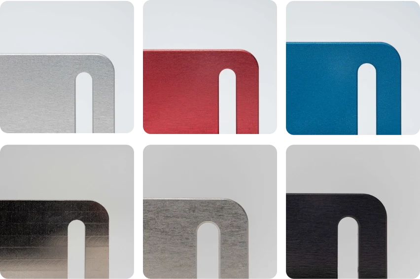
Surface Finishes & Heat Treatment
Surface finishing and heat treatment are specified according to wear, corrosion resistance, appearance, friction and dimensional priorities. Sequence matters: machining allowances, masking, distortion risk, grinding after treatment and final inspection requirements should be defined before release.
Upload a Drawing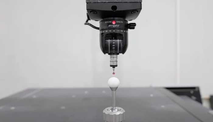
Quality, Metrology & Documentation
Precision inspection, metrology and quality documentation are planned around critical dimensions, datums and agreed acceptance criteria. Buyers should identify required reports, measurement methods, revision status, material evidence and any traceability needed for the order.
Upload a Drawing
Prototyping & Low-Volume Production
Rapid prototyping and low-volume manufacturing support drawing-driven validation, tooling development and controlled production quantities. A useful request identifies application context, material, revision, critical dimensions, surface priorities, quantity, target date and inspection or documentation needs.
Upload a DrawingMaterials for CNC Parts for Electronics Assembly Nests
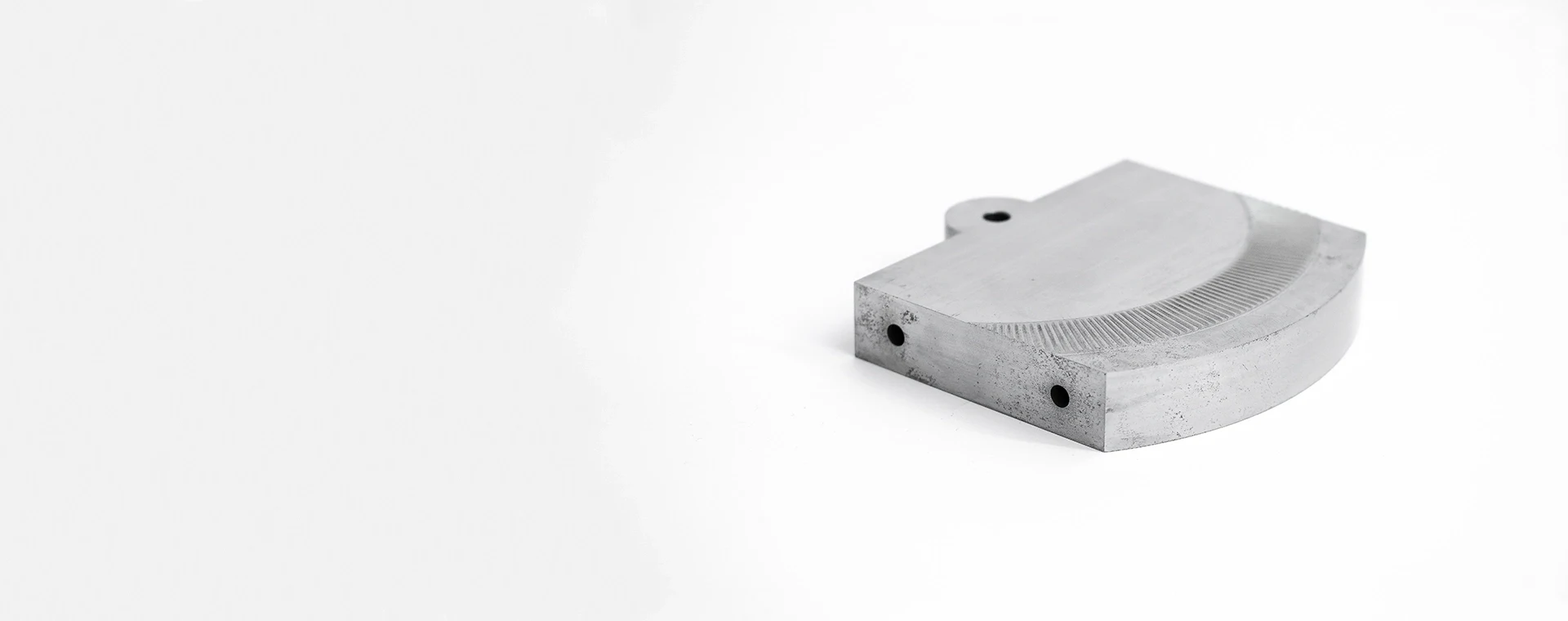
Tool Steel
Selected for rigid nest bodies, locators, and repeated contact features where wear resistance matters. Heat treatment, grinding stock, and distortion risk should be reviewed before final dimensions and inspection datums are committed.
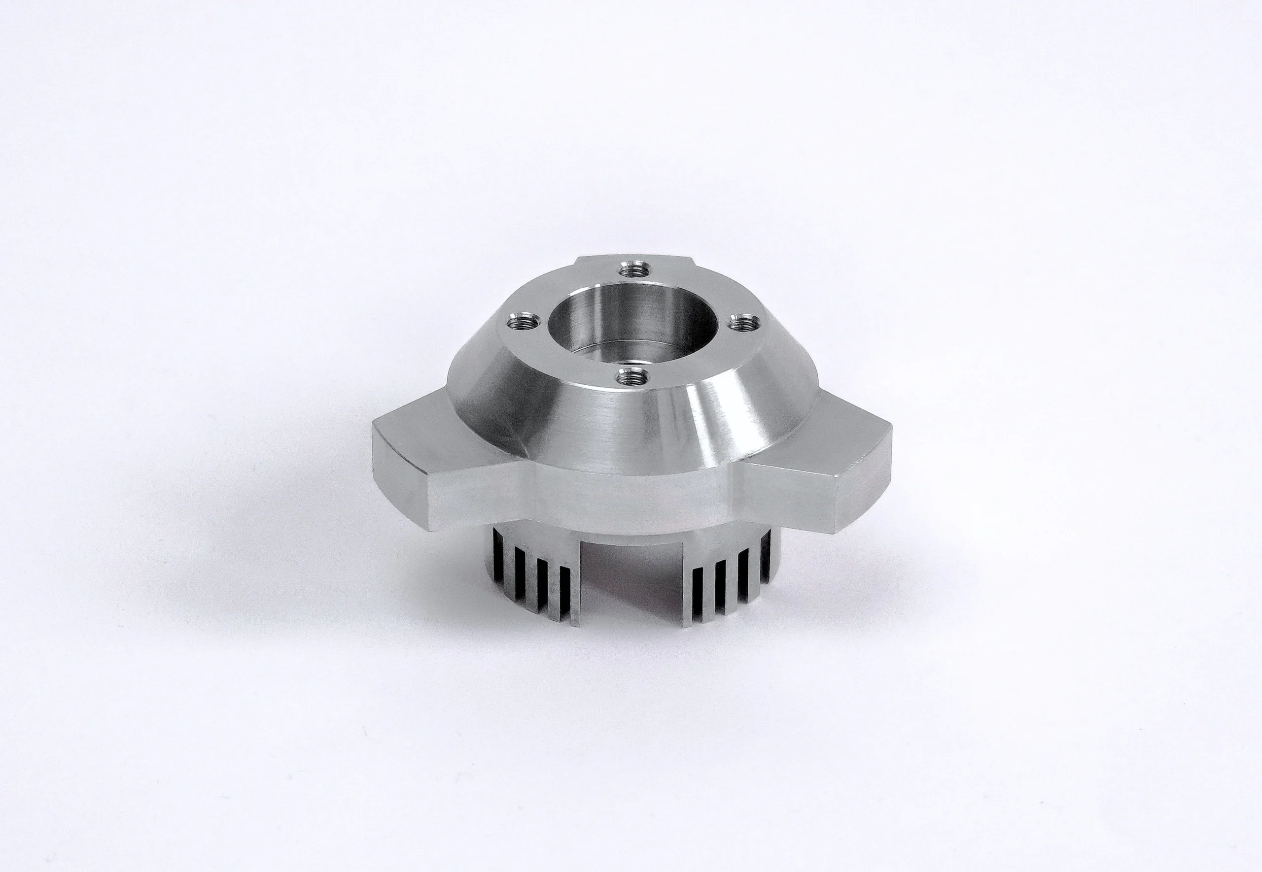
Stainless Steel
Considered for nests exposed to moisture, cleaning agents, or corrosion-sensitive environments. Its stiffness and corrosion behavior suit structural and locating features, while machining access, burr control, and finishing requirements need drawing review.
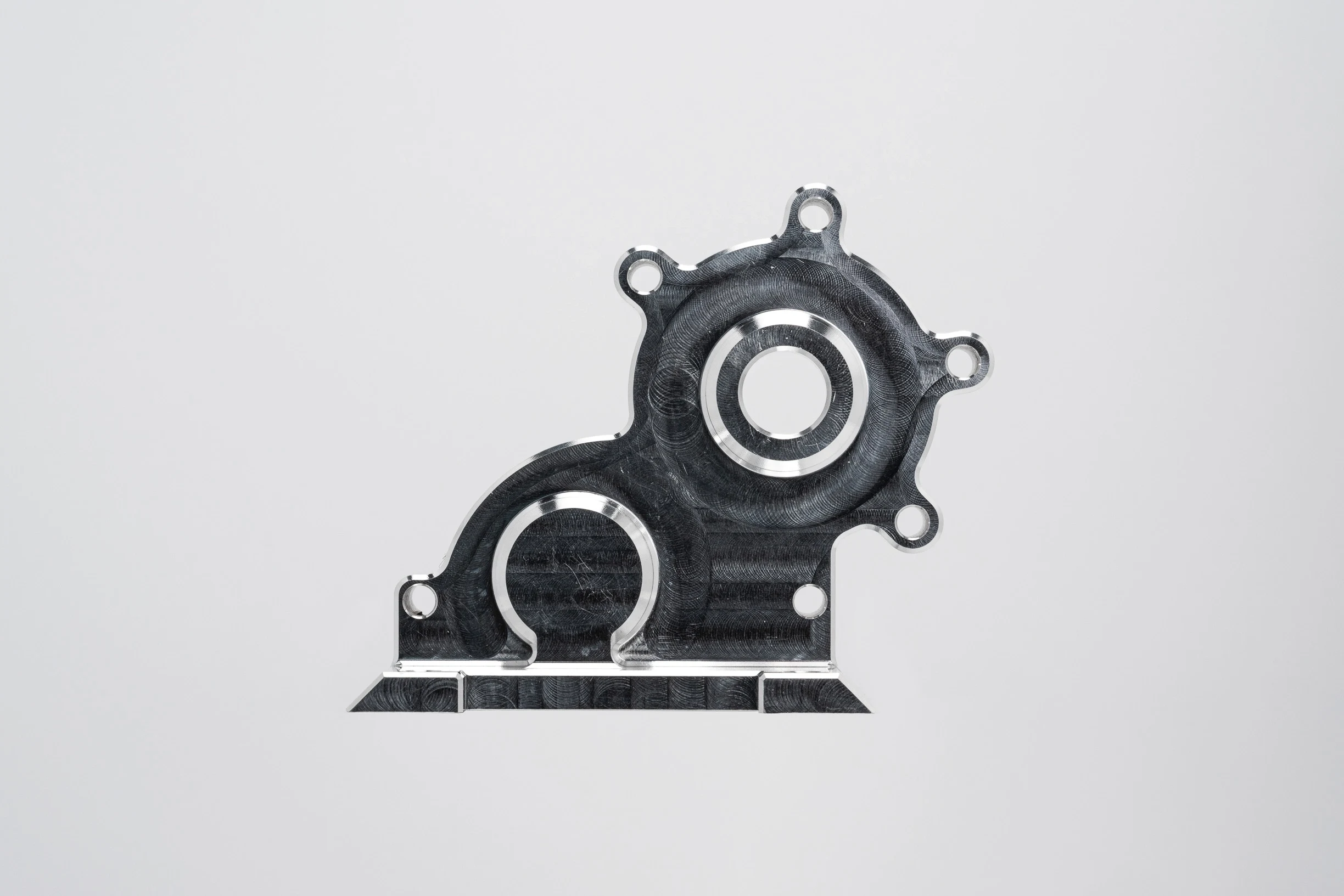
Aluminum Alloy
Used when lower mass, machinability, or thermal behavior is important for fixture bases and non-wearing supports. Surface protection, thread durability, and contact-zone reinforcement should be evaluated against the assembly cycle and handling conditions.
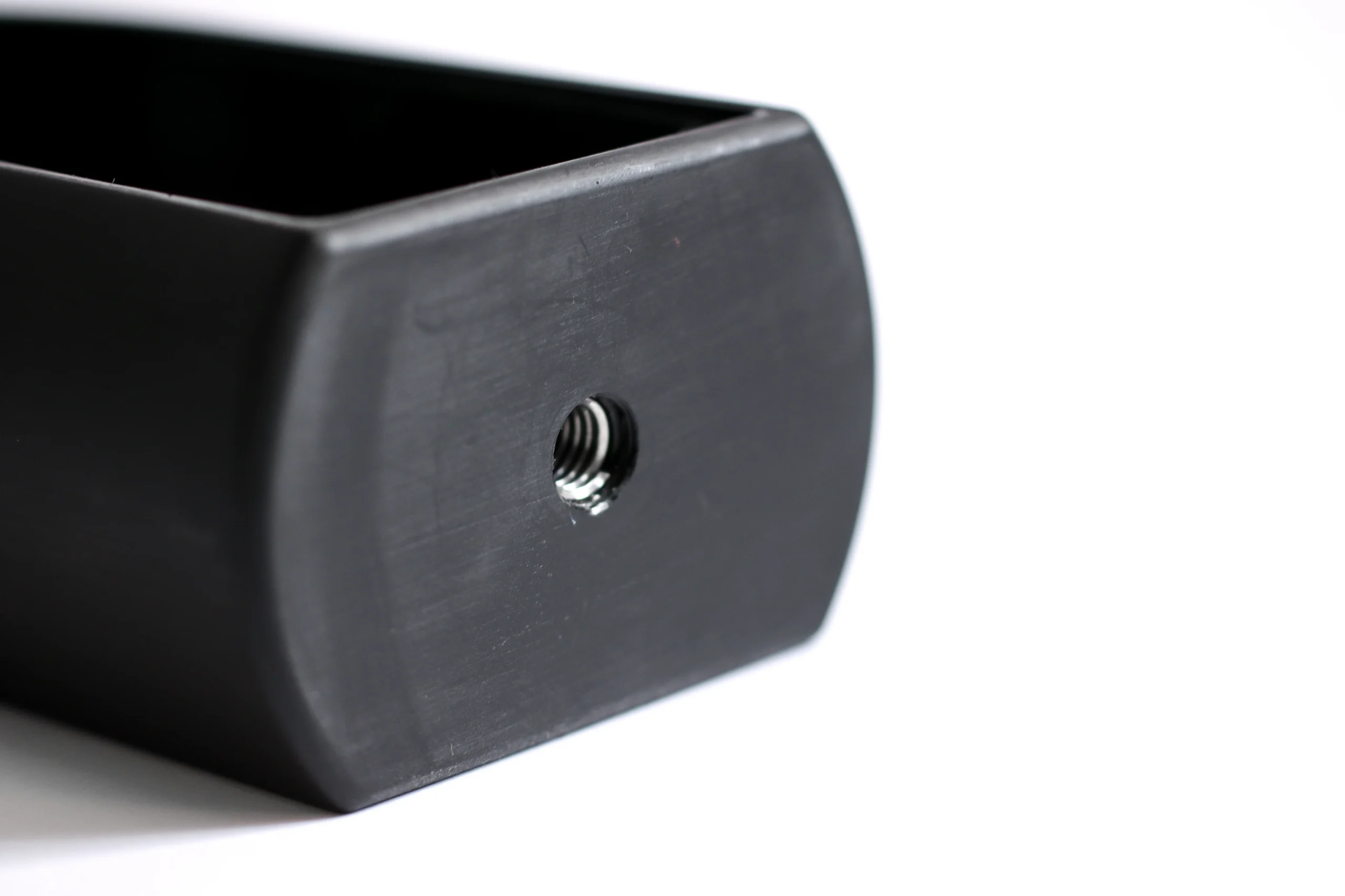
Engineering Plastics
Applied to non-marring, electrically insulating, or component-protective contact areas. Material grade, wall stiffness, thermal expansion, and fastening strategy should be checked so the nest maintains alignment under its actual operating environment.

Carbide Inserts
Specified conditionally for compact, high-wear contact points or precision locating features. The machining route may require grinding and EDM, with edge condition, mounting method, and mating-material behavior defined before production planning.
CNC Parts for Electronics Assembly Nests: Machining, EDM, and Grinding
CNC Milling
Milling establishes nest plates, pockets, mounting patterns, locating features, and accessible datum surfaces. Tool access, wall stability, clamping strategy, and burr-control requirements are reviewed to support repeatable assembly interfaces.
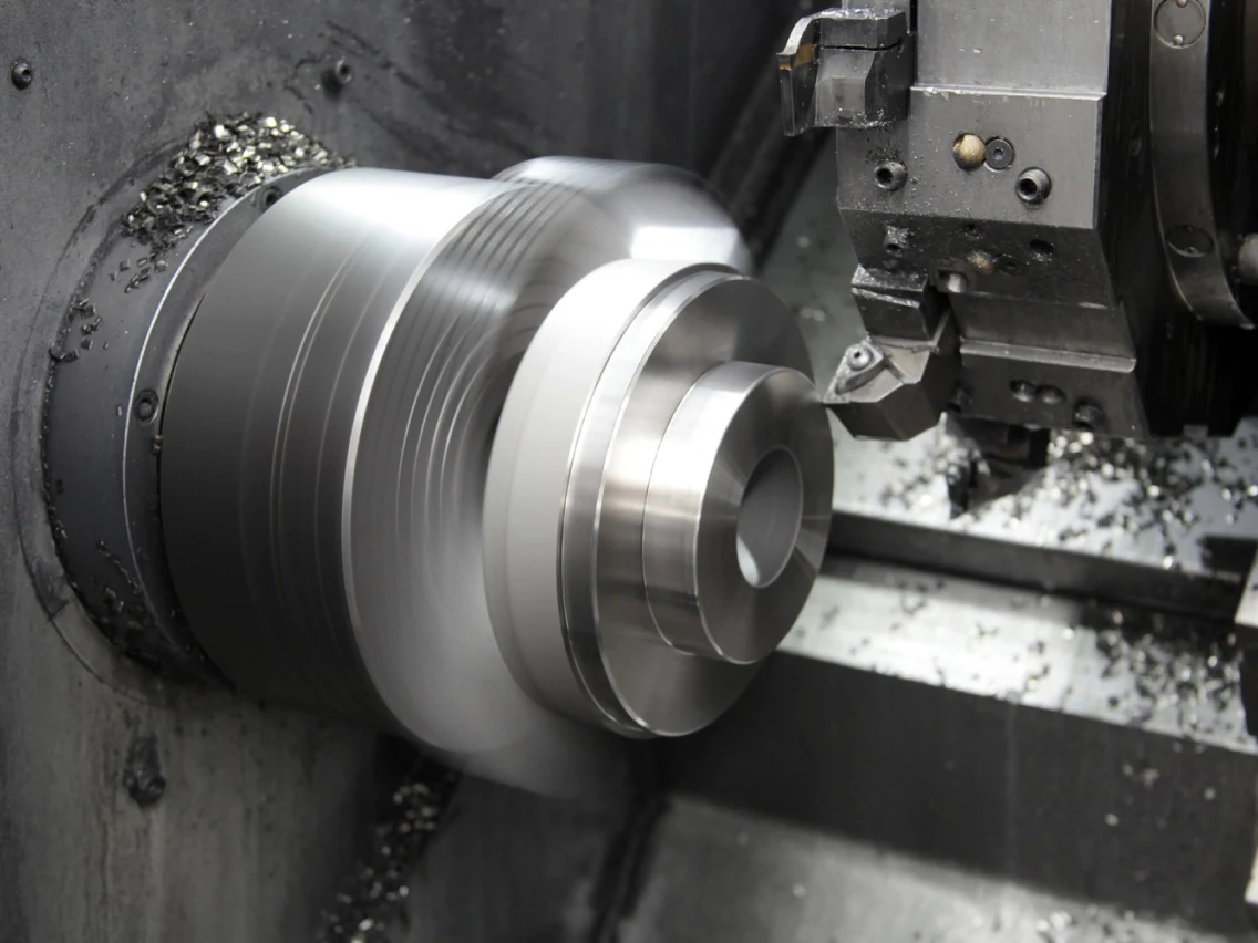
CNC Turning
Turning supports rotational details such as locating pins, sleeves, bushings, and stepped components used with assembly nests. Concentric features are planned from defined datums, with subsequent operations considered where mating surfaces require additional control.
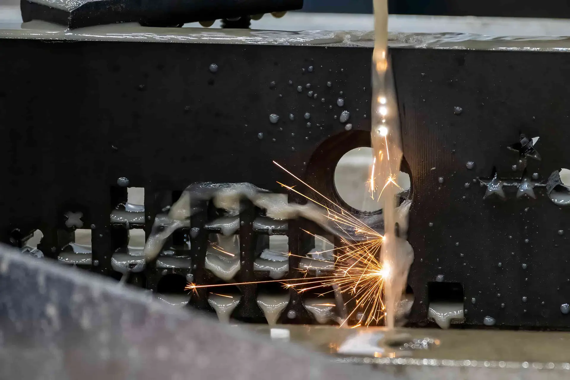
Wire EDM
Wire EDM is considered for conductive materials when narrow slots, internal profiles, sharp-corner requirements, or difficult-through features cannot be approached effectively by milling. Wire path, start-hole access, stock condition, and inspection references are reviewed first.
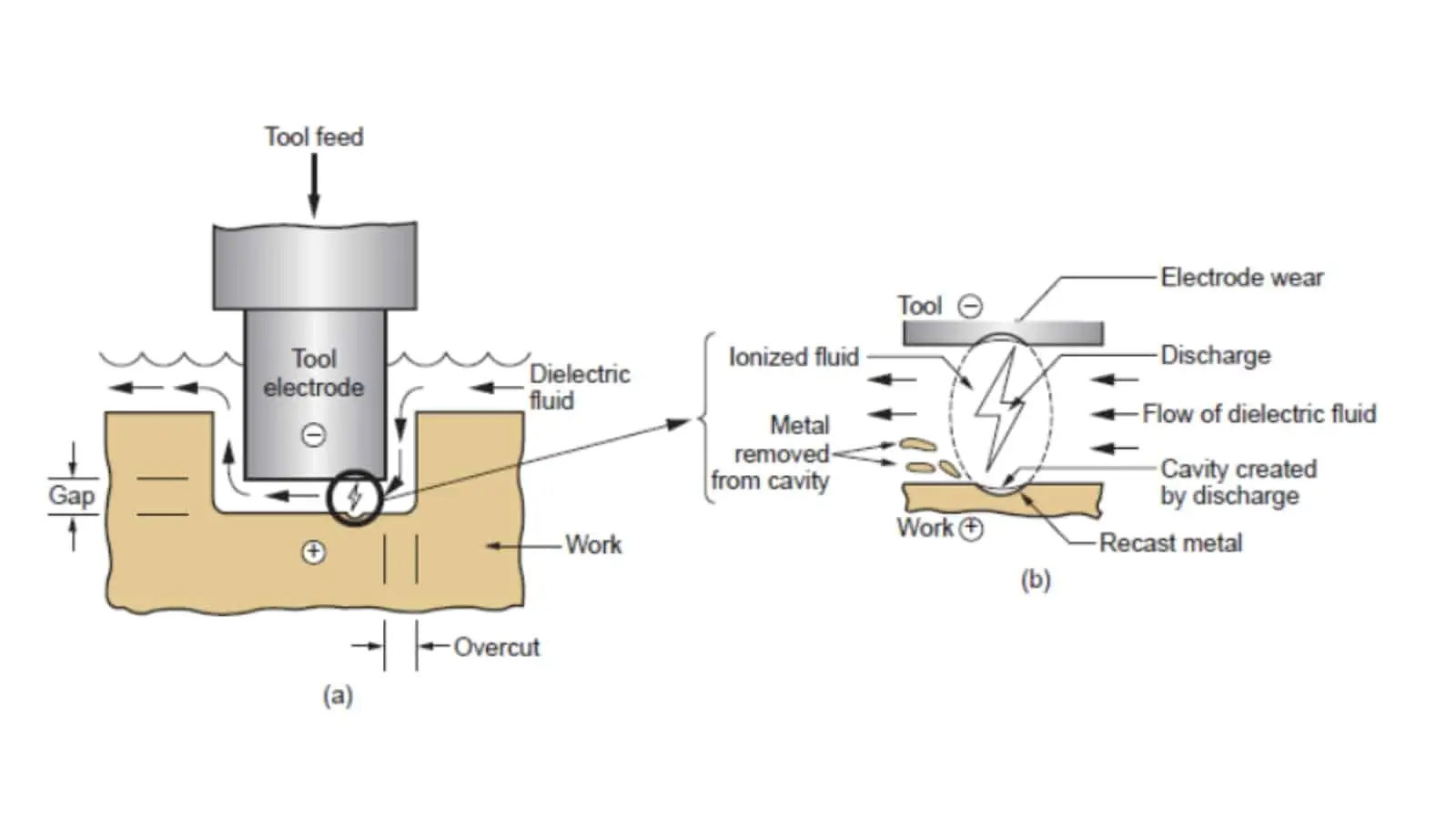
Sinker EDM
Sinker EDM can form detailed conductive-material cavities, blind internal geometry, and features with limited cutter access. Electrode design, spark allowance, surface requirements, and finishing strategy are coordinated with the part drawing and functional fit.

Precision Grinding
Precision grinding refines selected flat, parallel, cylindrical, or wear-related surfaces after machining or heat treatment where applicable. Grinding stock, datum sequence, and measurement access must be defined so the finished nest supports its intended location scheme.
Fitting Inspection
Fitting and inspection connect individual components to the assembly intent. Critical dimensions, mating relationships, surface condition, and reporting requirements are checked against the agreed drawing revision and inspection plan before shipment documentation is prepared.
Functional Details for CNC Parts for Electronics Assembly Nests
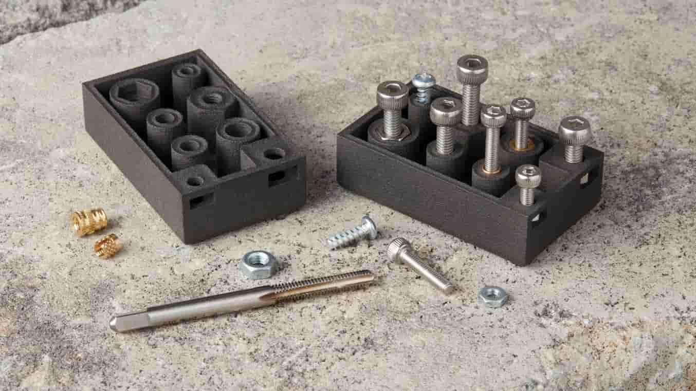
Threaded Inserts
Threaded inserts can provide durable fastening points in nest bodies or replaceable modules. Define insert type, thread size, installation method, pull-out considerations, and clearance around adjacent electronic components on the drawing.

Dowel Pins
Dowel pins establish repeatable location between nest plates, covers, and interchangeable tooling elements. Specify datum relationship, pin diameter, fit intent, engagement depth, and whether removal or service access is required.
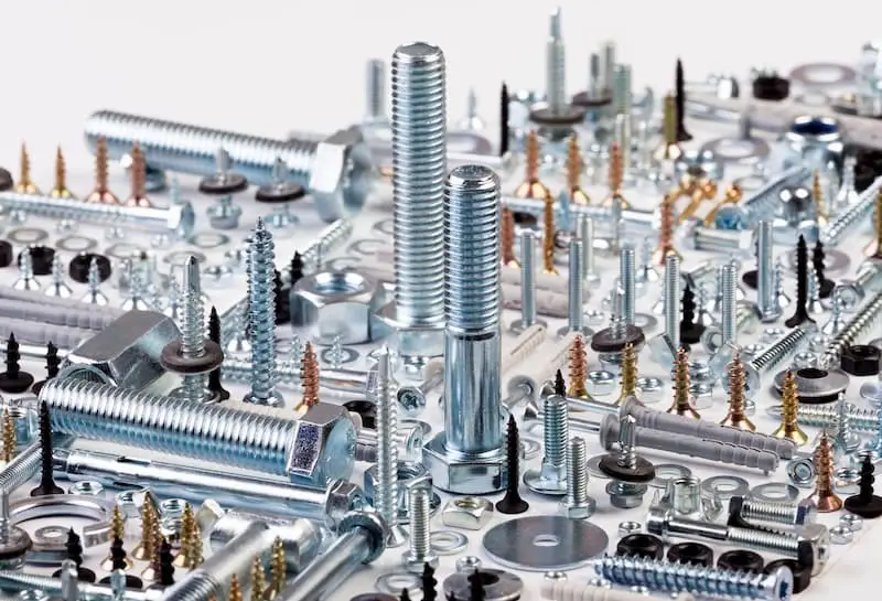
Captive Fasteners
Captive screws, shoulder bolts, and specified fasteners can secure electronics assembly nests while reducing loose-part risk during changeover. Identify thread callouts, head clearance, tightening access, and any mating-component constraints before production.
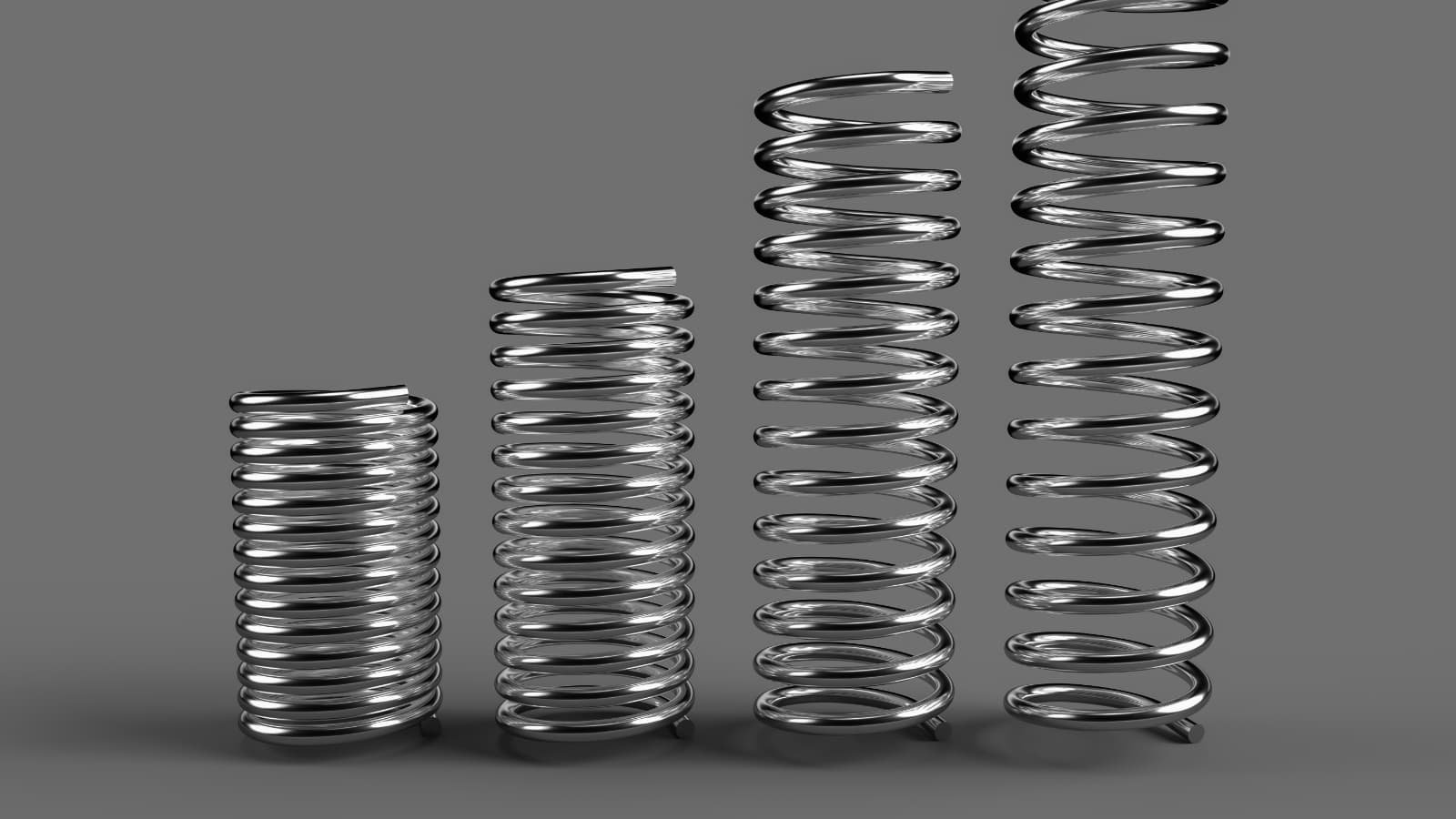
Compression Springs
Compression springs can support compliant clamping, part ejection, or controlled contact in a nest. Provide load range, working travel, installed height, pocket geometry, and expected cycling conditions for an appropriate design review.

Guide Elements
Guide pins, bushings, and lead-in features help align plates, connectors, or workpieces during loading. Their placement should relate to functional datums, insertion direction, clearance requirements, and the intended assembly sequence.
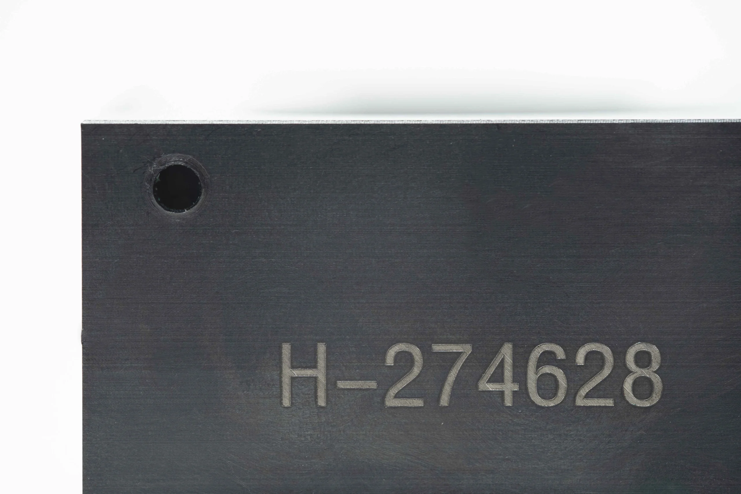
Identification Marking
Laser marking, engraved identifiers, revision labels, and orientation marks can support traceability and operator setup. Specify content, location, character size, contrast expectations, and whether marking must remain legible after cleaning or use.
About SUUXIANG Precision Manufacturing
SUUXIANG is the international-facing brand of Dongguan SuuXiang Precision Mold Co., Ltd., established in 2010 in Chang’an Town, Dongguan, Guangdong, China. We help global engineering, sourcing, and quality teams convert drawings and specifications into inspected custom parts, precision mold components, connector tooling, and CNC parts for electronics assembly nests.
Our work is planned around the part’s functional requirements. CNC milling and turning, multi-axis machining, EDM, precision grinding, fitting, and inspection are combined according to datum strategy, critical dimensions, material condition, tool access, and the required machining sequence.
What distinguishes SUUXIANG is disciplined project communication before production commitments. We review drawings and available 3D models for manufacturability, identify inspection priorities and revision requirements, then keep process and delivery information visible. Submit an RFQ with material, quantity, quality expectations, and target delivery requirements for a practical technical discussion.

CNC Parts for Electronics Assembly Nests: From Critical Dimensions to Inspected Components
DFM and Datum Review
SUUXIANG reviews the drawing, 3D model, mating context, and critical dimensions before quoting CNC parts for electronics assembly nests. The review clarifies functional datums, locating relationships, tool access, and tolerance stack risks so the manufacturing route reflects the intended assembly function.
- Identify primary, secondary, and tertiary functional datums
- Confirm PCB, connector, or housing locating interfaces
- Review thin sections, burr-sensitive edges, and cutter access
- Align critical features with practical inspection methods

EDM and Grinding Strategy
Where hardened material, internal profiles, fine slots, or wear-critical locating features call for it, SUUXIANG plans EDM and grinding alongside CNC machining. Electrode access, wire path, machining allowance, heat-treatment sequence, and finish requirements should be reviewed as connected decisions.
- Assess wire EDM access for enclosed or narrow profiles
- Define grinding stock before heat treatment and finishing
- Review electrode strategy for inaccessible internal features
- Separate functional finish requirements from noncritical surfaces
Coordinated Process Routes
Assembly nests often combine milled faces, turned details, EDM features, ground references, and fitted hardware. SUUXIANG coordinates these operations from the approved revision, maintaining visible handoffs between processes so a later operation does not compromise the datum relationship established earlier.
- Sequence machining around stable datum surfaces
- Protect reference features through heat treatment and finishing
- Coordinate fitted pins, bushings, clamps, and threaded hardware
- Keep drawing revisions visible across manufacturing operations

Inspection and Revision Control
Inspection planning for electronics assembly nest components begins with the features that control fit, alignment, and repeatability. SUUXIANG aligns the inspection method and final documentation with the order requirements, while keeping revision status and agreed quality expectations traceable throughout the project.
- Prioritize critical locating, seating, and clearance dimensions
- Match measurement methods to geometry and datum strategy
- Confirm required inspection reports before production release
- Maintain traceable revision and delivery communication
Why Choose SUUXIANG for CNC Parts for Electronics Assembly Nests
A disciplined workflow for reviewing drawings, planning process routes, controlling critical dimensions, and maintaining visible revision information.
← Swipe left or right to view →
Production Process for CNC Parts for Electronics Assembly Nests
Each project is planned around the drawing, critical dimensions, process access, inspection requirements, and revision-controlled delivery information.
Review Drawing Package
We review drawings, models, materials, quantity, datums, critical dimensions, surface requirements, mating context, and requested inspection documentation before confirming the manufacturing route.
Plan Material and Process
The team evaluates material condition, heat-treatment sequence, machining allowances, tool access, workholding, and whether milling, turning, EDM, grinding, or fitting is appropriate.
Machine Primary Geometry
CNC machining establishes the nest’s main form, mounting features, locating geometry, and accessible pockets while preserving stock for later precision operations where needed.
Finish EDM and Grinding
Wire or sinker EDM, precision grinding, and fitting address hard-to-machine profiles, fine clearances, datum-related surfaces, and fit-critical features identified during planning.
Inspect, Pack, Coordinate Shipment
Parts are inspected against the agreed plan, documentation is matched to the order, and protective packing and delivery coordination follow confirmed project requirements.
How to Work With SUUXIANG
Provide the technical inputs early so the machining route, inspection plan, and order documentation can be aligned before production begins.
Send Your Drawing Package
Upload 2D drawings and available 3D models for CNC parts for electronics assembly nests, including revision status, mating context, quantity, and target delivery date.
Define Critical Requirements
Specify material, heat treatment, critical dimensions, datums, surface requirements, inspection reports, packaging needs, and any functional conditions affecting nest fit or handling.
Review DFM and Quotation
Evaluate SUUXIANG feedback on tool access, EDM or grinding needs, machining allowances, inspection approach, assumptions, pricing, and proposed sampling or production details.
Approve Production Details
Confirm the controlled drawing revision, agreed process route, material requirements, quality expectations, quantity, and delivery plan before manufacturing begins.
Receive Inspected Components
Receive completed parts with documentation matched to the agreed inspection plan, plus visible revision and delivery information for your incoming-quality process.
CNC Parts for Electronics Assembly Nests: Certificates and Quality Documentation
Customer Reference Publication Controls
Approved customer case pending: publish only after the customer confirms the drawing scope, inspection evidence, production outcome, quotation details, and permission to use an attributable project statement.
Approved customer case pending: document the critical dimensions, datum strategy, process route, inspection report, revision status, and measurable assembly result before presenting this feedback as a SUUXIANG testimonial.
Approved customer case pending: include only customer-approved outcomes such as accepted quantities, documented delivery milestones, inspection findings, or reduced fitting iterations, supported by the applicable order and quality records.
FAQ: CNC Parts for Electronics Assembly Nests
Practical answers on feasibility review, sampling, inspection evidence, logistics, and drawing-based sourcing.
What information should I send for cnc parts for electronics assembly nests?
Can SUUXIANG quote low-volume cnc parts for electronics assembly nests?
How do you review drawings for cnc parts for electronics assembly nests?
Can I order samples before a larger assembly-nest order?
How should I plan lead time for a custom electronics assembly nest?
What inspection evidence can be requested with nest parts?
How are payment, shipping, and import details handled?
How is my drawing and IP handled during an RFQ?
Complete Buyer’s Guide to cnc parts for electronics assembly nests
Use this decision framework to specify, compare, and source precision assembly nests, assess capable suppliers, control quality risk, and avoid tolerance, material, inspection, and lead-time mistakes before production.
1. What Are cnc parts for electronics assembly nests?
Three functional jobs define cnc parts for electronics assembly nests: they locate an assembly from controlled datums, support it without distortion, and present it repeatedly for assembly, test, inspection, or connector operations. The nest is custom hardware designed around the part, its mating features, and the process station.
Two distinctions prevent specification errors. A nest is not a general enclosure, which primarily protects the finished product, nor a generic PCB fixture, which may only hold a board; it is also not a machine component unless it directly establishes the product’s process position.
One stable datum scheme reduces variation created by manual placement and helps shield delicate pins, flex circuits, optical surfaces, and cosmetic faces from unintended contact. For SUUXIANG drawing review, buyers should identify locating faces, allowable support contact, clamp direction, clearance zones, and the critical features each station must access.
2. How Electronics Assembly Nests Evolved
Two fixture generations are common in legacy electronics lines: hand-positioned bench supports and drilled plates that locate only the board or housing. They remain workable for stable products, but manual alignment makes repeatable probe contact, connector seating, and revision tracking harder to control.
Three linked design pressures changed the sourcing brief: finer connector pitch, denser PCB keep-out areas, and shorter engineering-change cycles. CAD-defined nests can combine datum features, replaceable wear or contact modules, sensor locations, cable routing, and controlled tool access before material is cut.
One RFQ package should now identify the mating components, assembly sequence, critical datums, allowable clamp loads, test-interface geometry, and revision state. For cnc parts for electronics assembly nests, ask the manufacturer to review machining access and tolerance stack-up with the fixture designer; a modular concept only reduces change cost when interfaces and inspection references are defined on the drawing.
3. Types of cnc parts for electronics assembly nests
CNC parts for electronics assembly nests should be classified by how they locate, support, restrain, and release the workpiece. The selected architecture must match the loading sequence, critical datum surfaces, and expected product revisions.
| Configuration | Function | Typical Features | Select When |
|---|---|---|---|
| Base plate | Common datum | Dowel holes, threads | Flat or modular tooling |
| Contoured nest | Orient irregular parts | Profiles, reliefs | Manual repeatable loading |
| Connector support | Back press-in force | Pin clearance, inserts | Connector insertion |
| Test fixture | Locate for verification | Probe access, datums | Inspection or testing |
| Vacuum/pneumatic | Retain during cycle | Ports, seals, vents | Hands-free handling |
| Modular nest | Change product interface | Base plus inserts | Variants or frequent revisions |
Location And Support Nests
Base plates provide a stable datum plane with dowel holes, threaded mounting points, and relief pockets. Select them for flat assemblies or as the common interface beneath replaceable tooling.
Contoured locating nests cradle irregular housings, PCB assemblies, or molded parts through machined profiles and clearance zones. Use manual loading when geometry needs repeatable orientation without clamp-induced distortion.
Process-Specific Nests
Connector insertion supports place backing directly beneath a connector or terminal during press-in loading. Add pin-clearance holes, replaceable wear inserts, and operator-safe lead-ins.
Test and inspection fixtures locate the product for probes, cameras, gauges, or electrical contacts. Choose dedicated datum features when measurement results must relate back to drawing datums.
Actuation And Changeover
Vacuum or pneumatic nests retain parts where hands-free loading, controlled seating, or automated handling is required. Specify sealing surfaces, ports, vent paths, and confirmation sensing with the application context.
Modular changeover nests separate the shared base, locating insert, wear element, and product-specific support. Split an integrated nest when revisions, wear, or product variants would otherwise require replacing the full assembly.
4. Materials for cnc parts for electronics assembly nests
6061-class aluminum is a common light base material, but stiffness alone does not make it safe for every contact surface. A drawing review should rank ESD behavior, cleaning chemistry, wear cycles, and allowable marking before selecting cnc parts for electronics assembly nests.
| Material | Best-Fit Use | Key Trade-Off | Contact Risk |
|---|---|---|---|
| Aluminum alloy | Light base plates | Lower wear resistance | Use protected contacts |
| Stainless steel | Cleanable structure | Higher weight | Finish-sensitive |
| Tool steel | Locating features | Corrosion control needed | High wear durability |
| POM | Soft contact pads | Lower stiffness | Low marking |
| PEEK | Heat or chemical exposure | Higher material cost | Validate finish |
| Acrylic | Viewing features | Brittle | Moderate marking risk |
| Carbide insert | Wear points | Difficult machining | Avoid direct contact |
Base And Wear Strategy
Tool steel supports durable locating edges; carbide inserts suit concentrated, high-cycle wear zones. Separate replaceable inserts from the main body when wear, service access, or revision risk is high.
Contact Surface Risks
POM provides low-friction, lower-marking contact, while PEEK better tolerates demanding heat or chemicals. Acrylic offers visibility but can crack or mark more readily; validate every cleaner and product finish.
Stability And ESD
Stainless steel resists many cleaning environments but adds mass; engineering plastics can move with temperature or moisture. Specify conductive or dissipative material only where the ESD path, resistance range, and grounding method are defined.
5. Surface Treatments and Functional Customization
Two finish decisions can alter fit, grounding, and service life after machining. For cnc parts for electronics assembly nests, define functional surfaces before quotation, not after inspection planning begins.
| Treatment | Primary Benefit | Key Trade-Off |
|---|---|---|
| Anodizing | Corrosion resistance | Insulating oxide; thickness affects fit |
| Hard anodizing | Higher wear resistance | More buildup and reduced conductivity |
| Nickel plating | Wear and corrosion control | Thickness requires tolerance allowance |
| Passivation | Stainless corrosion cleanup | Does not add a wear layer |
Select Functional Finishes
Three aluminum options are anodizing, hard anodizing, and bead blasting before anodizing; each can change cosmetic consistency and dimensions.
One plating callout should state thickness and masked zones: nickel improves wear and corrosion resistance but adds buildup; passivation protects suitable stainless surfaces.
Preserve Electrical Contacts
One ESD-conscious contact strategy identifies bare-metal pads, grounding fasteners, and any prohibited insulating finish.
Two identifier methods—laser marking and engraved text—need location, character height, contrast requirement, and whether readability must survive cleaning.
Specify Replaceable Features
Two locating features, dowel pins and bushings, require fit class, datum relationship, material, hardness, and replacement direction.
One vacuum-port callout needs thread, seal face, flow path, and plug requirements; interchangeable wear inserts need retention and revision identification.
6. Critical Construction and Quality Elements
Reliable cnc parts for electronics assembly nests begin with a functional datum scheme, not a blanket tight-tolerance note. Define how the part is seated, located, clamped, and released before selecting machining tolerances.
Datum And Pin Strategy
Three-point support establishes a stable primary plane; two secondary locators constrain in-plane movement, while one tertiary stop prevents rotation. Specify pin diameter, fit, insertion depth, and the datum features measured after machining.
0.5–1.0 mm lead-ins are commonly useful on locating holes or pockets, subject to the mating part and material. Keep pins away from fragile connectors, solder joints, and component keep-outs.
Machining Features That Matter
Flatness and parallelism should be applied only where seating, clamp load, or sensor alignment depends on them. Define pocket depth from the functional datum and leave cutter-radius relief or EDM access where sharp internal corners are essential.
0.2–0.5 mm edge breaks can reduce handling damage, but must not alter component registration. Call out burr-free edges near PCB surfaces, contact areas, and wire-routing paths.
Inspection And First Article
One first article should verify the agreed datum setup, critical-to-function dimensions, pin locations, pocket depths, and visible burr condition before repeat production. Match each inspection result to drawing revision, measurement method, and acceptance criteria.
A tolerance-stack review should allocate error across the nest, pins, mating component, and clamp path. Mark only function-driving dimensions as critical; tolerancing every feature tightly raises cost without improving repeatability.
7. Choosing a CNC Assembly-Nest Manufacturer
Two RFQ inputs—the controlled 2D drawing and 3D model—let a supplier review datums, tolerance stack, clamping, tool access, and inspection before quoting. Ask for project-specific evidence, not generic claims of tight tolerances.
| Evaluation Area | Ask The Supplier | Request Evidence |
|---|---|---|
| DFM review | How are critical datums verified? | Marked-up drawing, risk list |
| Process control | Which route makes each feature? | Route and revision record |
| Inspection | How will critical features be measured? | Inspection plan and sample report |
| Delivery management | How are changes communicated? | Milestone and exception process |
Review The DFM Response
Three questions expose review quality: Which dimensions are critical? What datum scheme controls them? Which features require EDM, grinding, or revised radii?
Two requested records are useful: marked-up drawings and a written DFM response identifying risks, assumptions, and open decisions.
Verify The Process Route
Four linked operations—CNC machining, EDM, grinding, and fitting—should be assigned feature by feature. Ask whether material traceability, heat-treatment sequence, machining allowance, and electrode or wire path are documented.
One prototype route should remain traceable into low-volume repeats, including approved revisions and process changes.
Confirm Inspection And Delivery
Three deliverables should match the purchase order: inspection report, material evidence when required, and revision-controlled packing identification. Confirm inspection methods for critical features rather than accepting a blanket capability statement.
One accountable contact should report drawing questions, production status, inspection exceptions, and delivery changes early.
8. Common Buyer Mistakes With Assembly Nests
Eight recurring RFQ gaps turn a simple nest into a late-stage fit, safety, or yield problem. Resolve them during drawing review, before material is ordered or programs are released.
Datums And Mating Data
Datum A must locate the functional assembly, not merely a convenient machined face. Ambiguous datums create stack-up disputes; define primary, secondary, and tertiary references on the drawing.
One representative assembly sample or controlled mating-part model exposes interference early. Missing interface data forces assumptions; provide PCB, housing, connector, and allowable-contact details.
Material And Operator Use
Material cost is only one input to nest selection. A low-price grade can wear, mark parts, or lack stiffness; state contact loads, cycles, environment, and cosmetic restrictions.
Operator loading needs lead-ins, finger clearance, and a defined release method. Unspecified edge breaks leave burrs that snag assemblies or injure operators; identify all touch and contact edges.
Inspection Before Release
CNC machining follows a program; it does not independently define acceptance. Missing inspection criteria cause conflicting judgments; identify CTQ features, datums, gauges, sampling, and report requirements.
A DFM review before design freeze tests tool access, clamping, tolerances, and inspection reach. Frozen drawings can require costly rework; issue revisions under controlled change records.
9. Launching cnc parts for electronics assembly nests
A 7-stage launch keeps cnc parts for electronics assembly nests aligned with the product, process, and acceptance plan. Begin with controlled source files, then release only after each physical and documentary checkpoint closes.
Package The Requirements
Stage 1: provide the revision-controlled 2D drawing, native or neutral 3D model, BOM, material, finish, quantity forecast, and target date. Define primary datums, critical features, measurement method, and mating PCB, housing, connector, or fastener interfaces.
- Approved drawing revision
- 3D model and BOM
- Datum and CTQ schedule
- Mating-part geometry
- Finish and acceptance requirements
Review And Prove The Build
Stage 2: ask the supplier to return a DFM review covering tool access, clamping, tolerance stack, machining allowance, and proposed inspection approach. Stage 3: build a prototype, then run a fit-and-function trial using production-intent mating parts and record every interference or handling issue.
Approve And Control Release
Stage 4: approve the first article against the agreed drawing and acceptance plan; retain inspection results with the revision. Stages 5–7: issue revisions through a documented change notice, validate pilot use, then release repeat orders only with the approved configuration and forecast.
10. CNC Assembly-Nest Pricing and Lead Times
1 drawing revision can change the route more than the nominal part size: stock material, geometry, tolerance burden, setups, tool access, EDM or grinding, inserts, hardware, treatment, and inspection all affect cost. Quote the released 2D drawing, model, datum scheme, CTQs, material condition, finish, inspection plan, and target date together.
3 quantity tiers expose different economics. Prototype work concentrates programming, fixturing, and first-article verification in few pieces; pilot quantities can distribute setup effort, while repeat production may justify dedicated fixtures, controlled replenishment, and sampling plans. Revision risk remains a cost and schedule driver until the drawing baseline and change-control method are agreed.
| Quantity tier | Typical cost drivers | Typical lead-time drivers |
|---|---|---|
| Prototype: 1–5 | Programming, setups, material availability, full inspection | DFM closure, machining route, first article |
| Pilot: 6–50 | Setup spread, inserts and hardware, treatment batches | Fixture refinement, outsourced processes, approval timing |
| Repeat production: 51+ | Dedicated fixturing, lot planning, sampling, revision control | Material releases, batch scheduling, replenishment forecast |
Upload Drawings for CNC Parts for Electronics Assembly Nests
Include your model, material, quantity, critical dimensions, inspection requirements, and target delivery date for a focused DFM and quotation review.