
CNC Parts for Packaging Changeover Tooling, Inspected
SUUXIANG reviews drawings, critical dimensions, datums, and inspection needs before producing cnc parts for packaging changeover tooling.
Featured Components for Packaging Changeover Tooling





Related Drawing-Based Components and Quotation


Why CNC Parts for Packaging Changeover Tooling Need Drawing-Led Control
SUUXIANG reviews the dimensions, interfaces, and process decisions that determine whether custom tooling fits, repeats, and can be inspected against the order.
DFM Before Commitment
Review tool access, wall conditions, clamping approach, and machining sequence before quotation and production commitments are finalized.
Critical Dimensions Defined
Identify interfaces, functional fits, and critical-to-quality dimensions so machining and inspection focus on what affects changeover performance.
Datum Strategy Reviewed
Align datum references with mating components and measurement methods to reduce ambiguity across setup, machining, fitting, and final inspection.
Process Route Planned
Select appropriate CNC machining, EDM, grinding, and fitting steps according to geometry, material condition, surface requirements, and access.
Inspection Plan Matched
Define inspection methods and reporting expectations around agreed critical features, ensuring final documentation corresponds to the verified order requirements.
Revisions Stay Visible
Maintain clear drawing revision and delivery information throughout coordination, helping teams avoid producing to superseded changeover-tooling requirements.
CNC Parts for Packaging Changeover Tooling
Drawing-driven components for repeatable changeover, controlled datum relationships, and inspection-ready assembly across packaging tooling and related production equipment.

CNC Machining Services
Precision CNC machining services for drawing-based changeover parts and custom machined parts, including guides, shafts, plates, nests, and custom interfaces. Review focuses on critical dimensions, datums, material requirements, machining access, and the inspection evidence needed before production is committed.
Upload a Drawing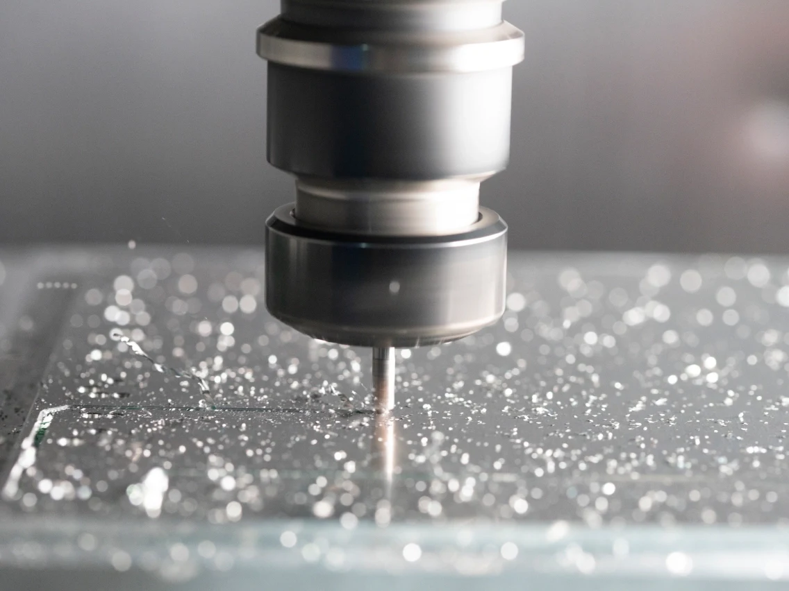
CNC Milling
Custom CNC milling services for tooling plates, fixture bases, nest bodies, and formed change parts requiring controlled hole patterns, pockets, slots, and datum faces. DFM review addresses tool access, clamping strategy, wall geometry, and tolerances that affect assembly repeatability.
Upload a Drawing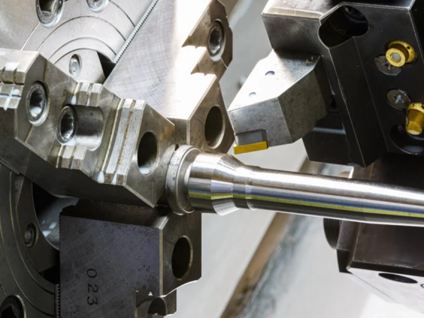
CNC Turning
Precision CNC turning services for shafts, bushings, collars, rollers, spacers, and other rotational packaging-tooling components. Drawing review considers concentricity, runout, bearing or mating fits, surface requirements, and secondary machining features required for installation.
Upload a Drawing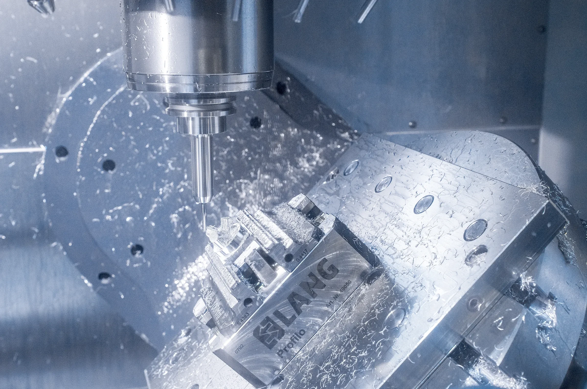
5-Axis Machining
5-axis CNC machining supports complex changeover components with angled faces, compound profiles, and multiple functional features that benefit from fewer setups. Process planning evaluates tool reach, workholding, datum transfer, and inspection access before selecting the machining route.
Upload a Drawing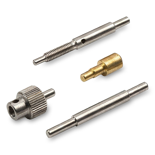
Swiss & Micro Machining
Swiss machining and micro machining support small-diameter pins, shafts, probes, sleeves, and compact locating features where geometry and handling demand careful process control. Requirements should define critical diameters, length-to-diameter relationships, material, and inspection priorities.
Upload a Drawing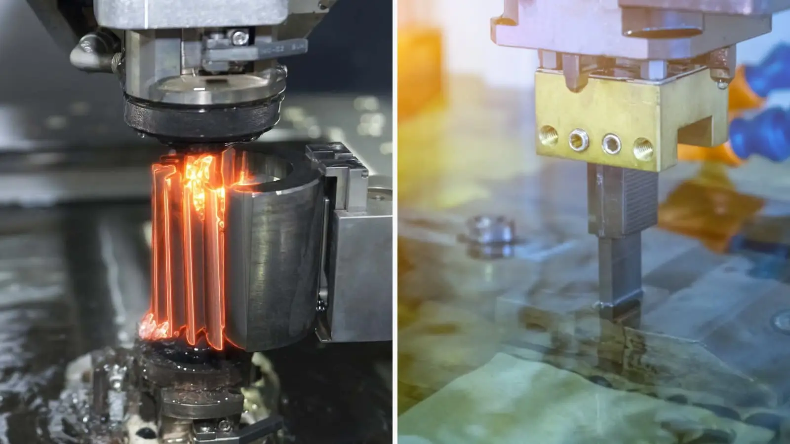
Wire & Sinker EDM
Wire EDM and sinker EDM services address hardened profiles, narrow slots, sharp internal corners, intricate cavities, and features inaccessible by conventional cutting. Electrode strategy, wire path, skim requirements, recast-layer considerations, and inspection criteria are reviewed against the drawing.
Upload a Drawing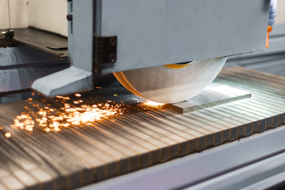
Precision Grinding
Precision surface and profile grinding is used where flatness, parallelism, profile control, or functional sliding fit depends on a controlled finishing process. Planning accounts for heat-treatment sequence, machining allowance, grinding stock, datum references, and the specified measurement method.
Upload a Drawing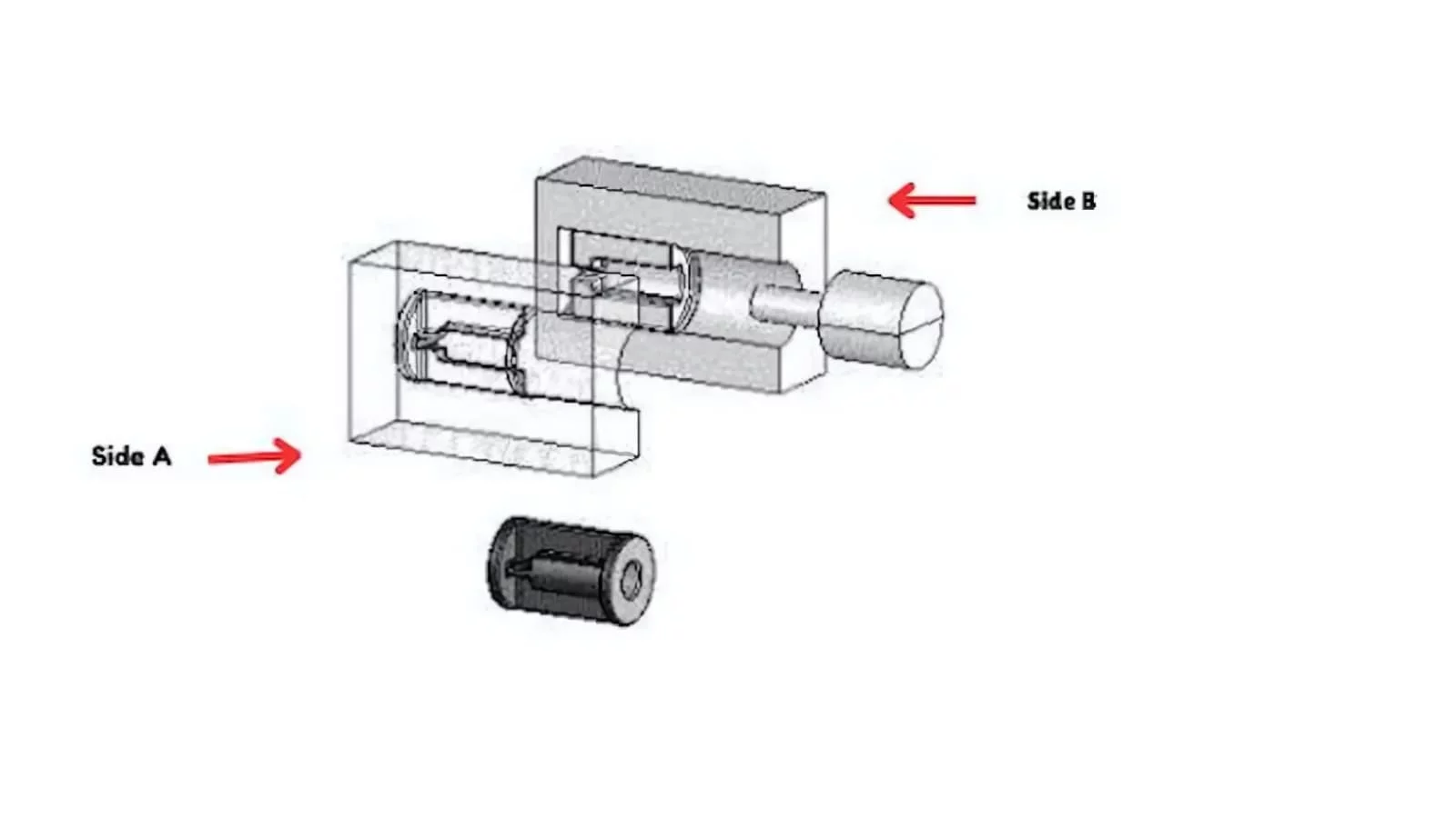
Mold Core Inserts & Mold Cavity Inserts
Precision mold core and cavity inserts are produced from customer drawings for molding applications where shutoff geometry, cavity detail, cooling interfaces, and datum control matter. The appropriate CNC, EDM, grinding, fitting, and inspection route is defined from the part requirements.
Upload a Drawing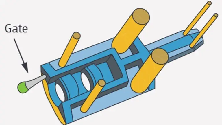
Ejector & Ejection Components
Ejector pins, sleeves, and ejection components are configurable mold-part families requiring attention to clearance, concentricity, wear surfaces, hardness requirements, and mating relationships. Drawings should identify critical diameters, travel-related interfaces, material, and surface expectations.
Upload a Drawing
Core Pins, Guide & Locating Components
Core pins, guide pins, and locating components establish repeatable mold alignment and functional positioning. Production planning reviews fit class, datum scheme, straightness, surface condition, heat treatment, and mating-component dimensions so components are evaluated as an assembly interface.
Upload a Drawing
Slides, Lifters, Gates & Mold Accessories
Mold slides, lifters, gates, and accessories support movement, release, feeding, and auxiliary functions within a tool. Their manufacturability depends on motion paths, shutoffs, contact surfaces, machining access, EDM needs, fitting allowance, and the requested inspection plan.
Upload a Drawing
Connector Mold Components
Precision connector mold components support tooling for connector products with fine features, closely controlled positional relationships, and demanding mating geometry. Review includes material selection, pin or cavity detail, EDM and grinding strategy, datum control, and inspection documentation.
Upload a Drawing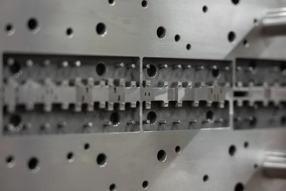
Stamping Die Components
Precision stamping die components include punches, dies, plates, guides, and custom forming elements made to drawing-defined geometry. Process planning considers wear areas, clearance relationships, material and heat treatment, grinding requirements, and dimensional verification after finishing.
Upload a Drawing
Injection Mold Components, MIM, CIM & Overmolding Tooling
Injection, MIM, CIM, and overmolding tooling components are evaluated within verified production scope. Drawings should clarify molded-material context, cavity or core function, shutoffs, venting or gating interfaces, surface requirements, and any fitting relationships affecting tool performance.
Upload a Drawing
Machining Materials
CNC machining materials are selected from drawing and application requirements rather than assumed from a generic list. An RFQ should state the specified grade, condition, material traceability needs, heat-treatment sequence, corrosion or wear considerations, and any approved substitution limits.
Upload a Drawing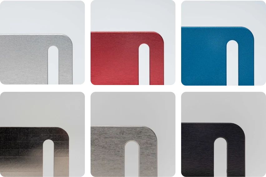
Surface Finishes & Heat Treatment
Surface finishing and heat treatment are planned around functional requirements such as wear resistance, corrosion behavior, friction, appearance, or mating fit. Specify the required process, coverage areas, final condition, masking needs, and dimensions that must be verified after treatment.
Upload a Drawing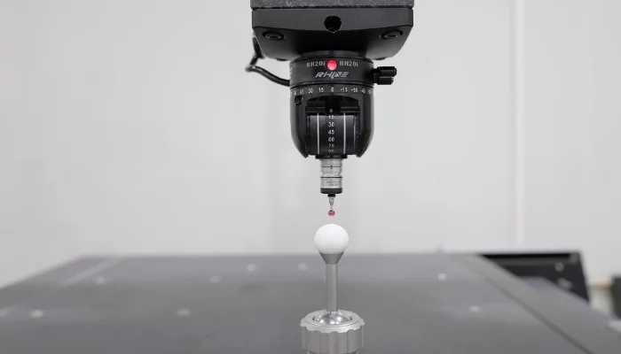
Quality, Metrology & Documentation
Precision inspection, metrology, and quality documentation are aligned to the drawing’s critical dimensions, datums, and acceptance criteria. Requirements may include dimensional reports, material records, revision identification, inspection method expectations, and order-specific traceability evidence.
Upload a Drawing
Prototyping & Low-Volume Production
Rapid prototyping and low-volume manufacturing support drawing revisions, production trials, replacement parts, and limited equipment builds. A useful RFQ identifies quantity, target delivery date, revision level, material, critical features, surface needs, and required inspection documentation.
Upload a DrawingMaterials for CNC Parts for Packaging Changeover Tooling
Stainless Steel
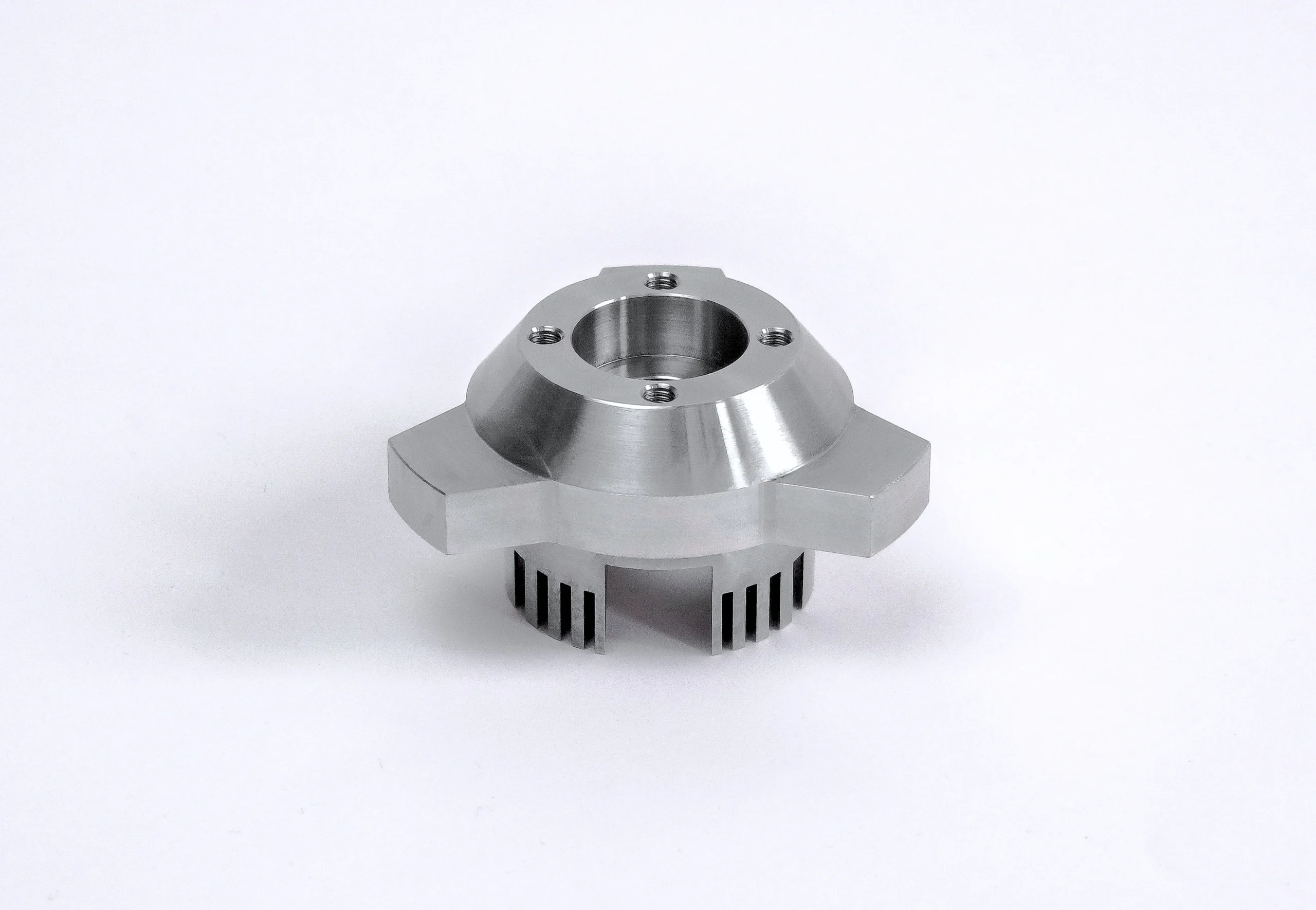
A corrosion-conscious choice for change parts exposed to washdown, moisture, or cleaning chemicals. Grade selection, surface finish, and any heat-treatment requirement should be reviewed against the drawing and actual packaging-line environment.
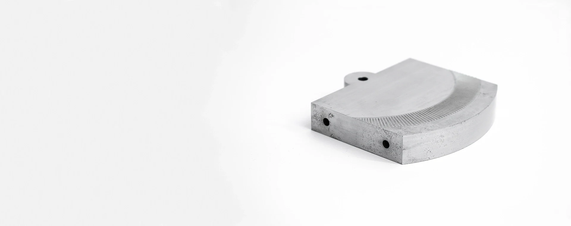
Tool Steel
Used where repeated contact, edge wear, or stable locating surfaces drive the requirement. Tool-steel selection depends on hardness, heat-treatment sequence, grinding stock, and the critical dimensions that must remain controlled after treatment.
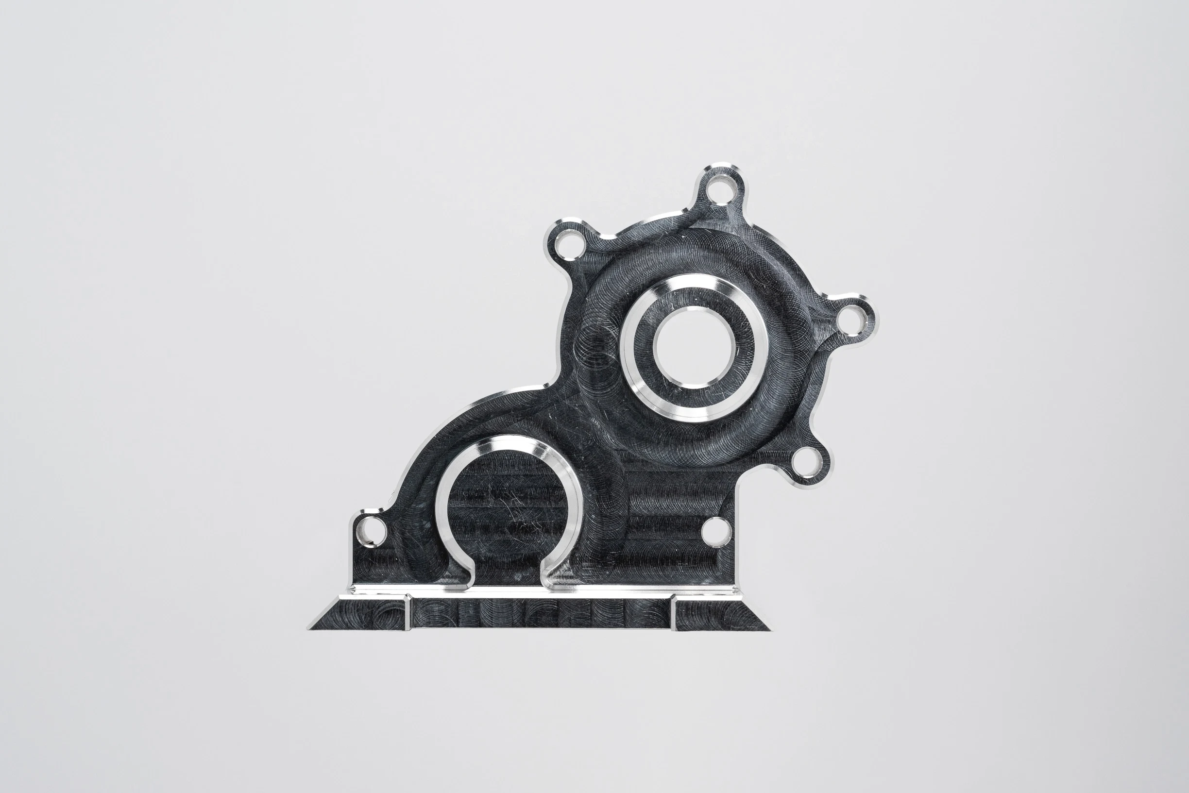
Aluminum Alloys
A practical option for lightweight format parts, mounting plates, nests, and handling fixtures where rapid adjustment matters. Alloy choice should balance stiffness, machinability, surface protection, and the load path defined by the assembly.
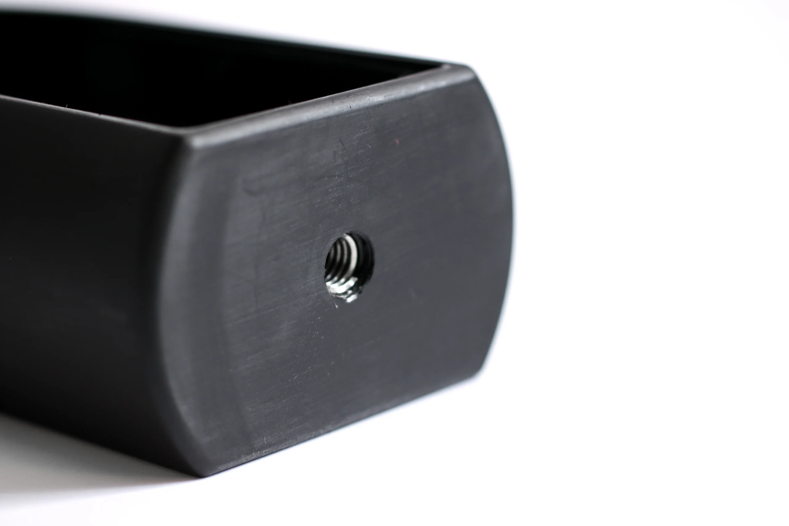
Engineering Plastics
Suitable for low-friction guides, product-contact interfaces, and wear components when reduced marking or quieter movement is important. Material selection should consider chemical exposure, dimensional stability, creep, and the required fit with mating hardware.
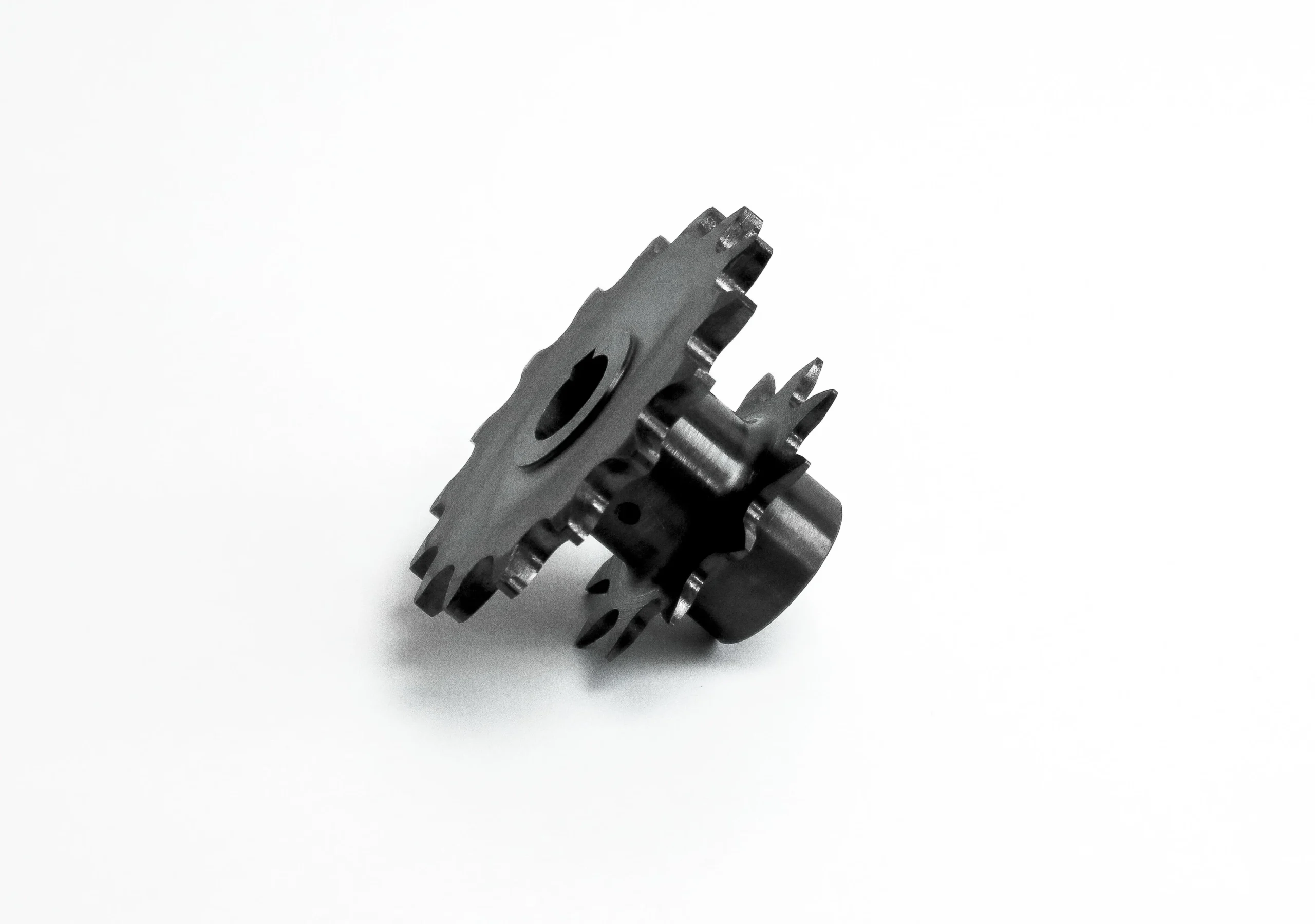
Carbon Steel
Often considered for robust structural tooling elements, shafts, brackets, and non-corrosive service conditions. The drawing review should clarify coating needs, hardness, machining allowance, corrosion exposure, and inspection points before production planning.
CNC Parts for Packaging Changeover Tooling: Process Routes
CNC Milling
Milling creates pockets, profiles, mounting faces, guide features, and datum surfaces on format plates, nests, rails, and change parts. Multi-axis access is reviewed where feature orientation or setup reduction affects dimensional relationships.
CNC Turning
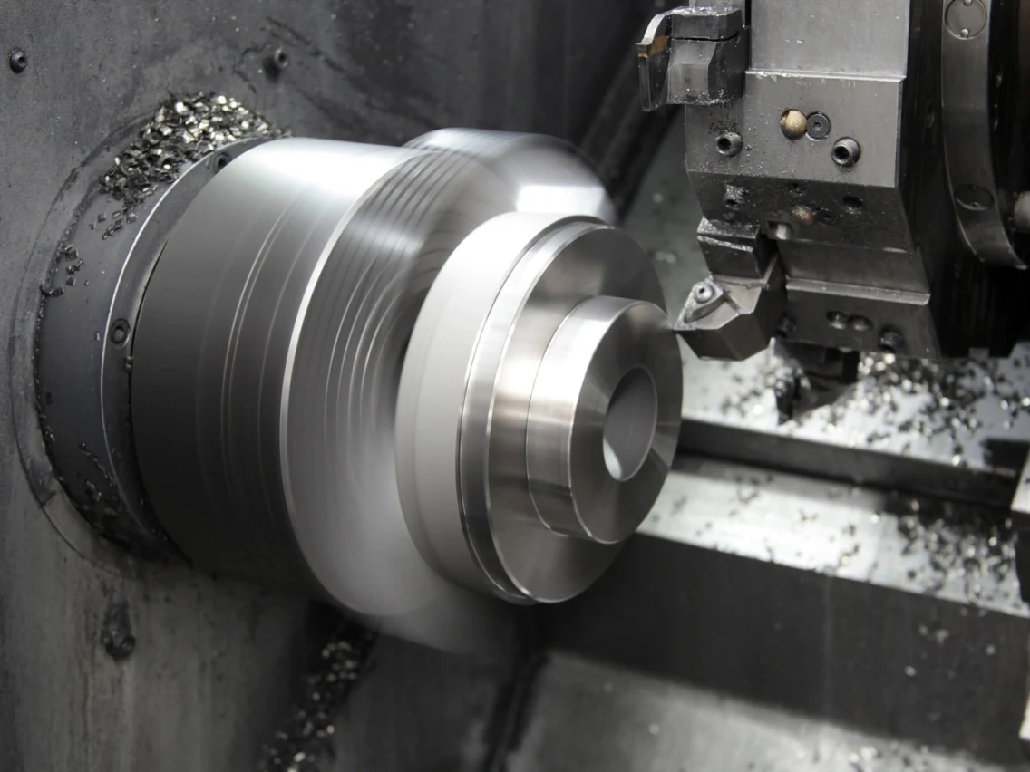
Turning supports shafts, rollers, bushings, chucks, and concentric cylindrical features. The process route is assessed against diameter control, runout, bearing interfaces, thread details, and any secondary milling or grinding requirements.
Wire EDM
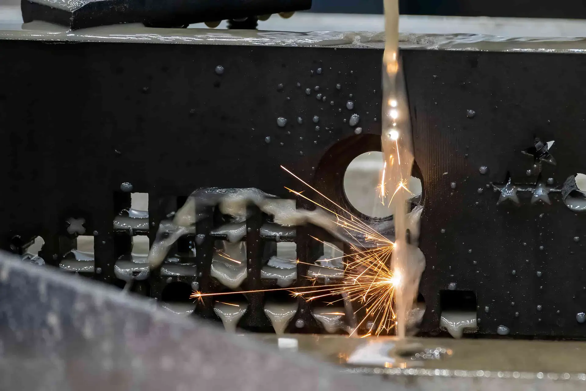
Wire EDM cuts precise profiles, narrow slots, internal contours, and hardened features where cutter access is limited. Wire path, corner conditions, start holes, and datum references should be defined before production planning.
Sinker EDM
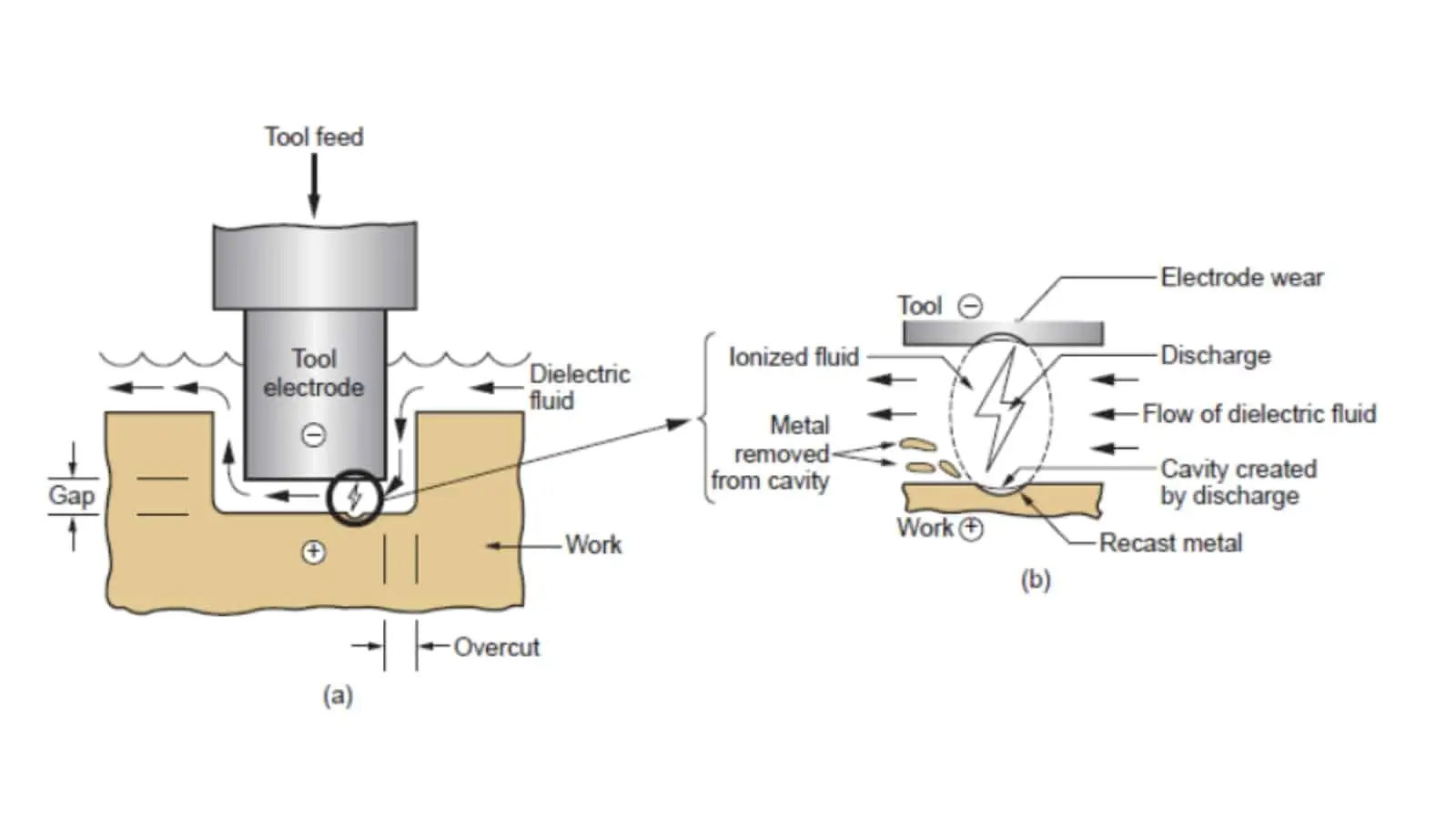
Sinker EDM forms deep cavities, sharp internal geometry, and difficult-to-reach details using planned electrodes. Electrode strategy, spark allowance, surface condition, and subsequent fitting or polishing needs are reviewed against the drawing.

Precision Grinding
Grinding refines critical flats, diameters, parallelism, and contact surfaces after machining or heat treatment. Grinding stock, datum sequence, surface requirement, and inspection method are confirmed to protect the intended assembly fit.
Fitting Inspection
Fitting and inspection verify mating relationships, functional movement, critical dimensions, and documented requirements before release. SUUXIANG aligns measurement methods and reporting expectations with the order, drawing revision, and agreed quality plan.
CNC Parts for Packaging Changeover Tooling: Hardware and Applied Features
Locating Pins
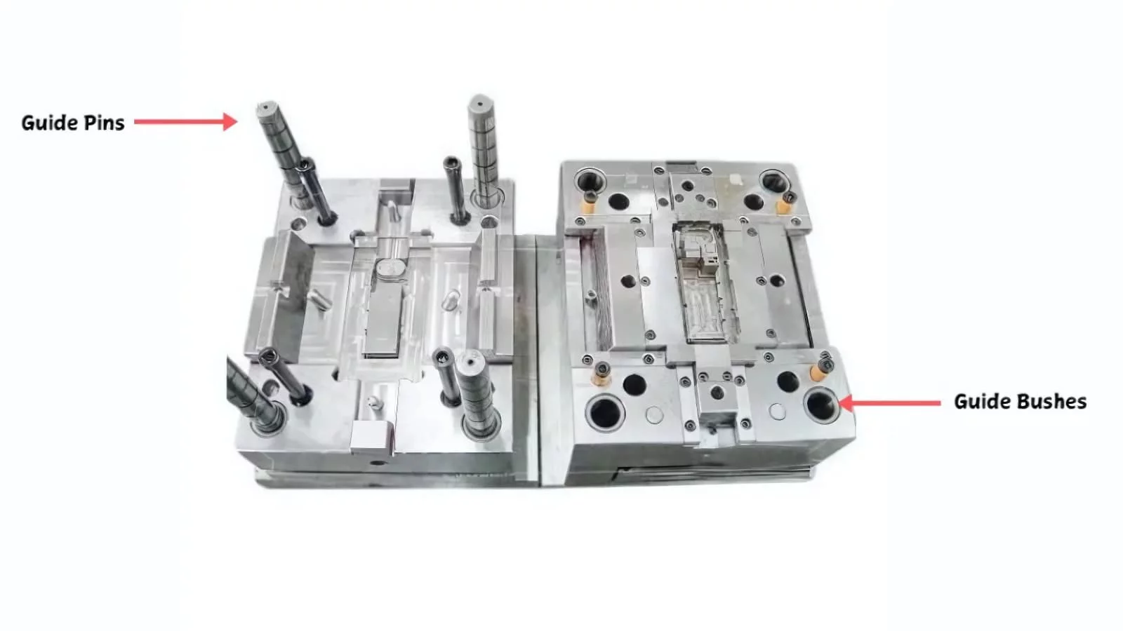
Dowel, taper, or shoulder locating elements establish repeatable relationships between format parts, base plates, and machine interfaces. Define datum references, fit requirements, retention method, and access for installation or removal in the drawing package.
Guide Components
Guide rails, bushings, rollers, and lead-in features support controlled product or tooling movement during setup and operation. Review contact surfaces, alignment requirements, wear conditions, cleaning exposure, and the mating geometry before selecting a process route.

Fastening Interfaces
Threaded holes, captive hardware provisions, clamp interfaces, and clearance features can be machined around the assembly sequence. Identify fastener specification, torque-sensitive surfaces, tool access, and any repeat-service requirement to prevent interference at installation.
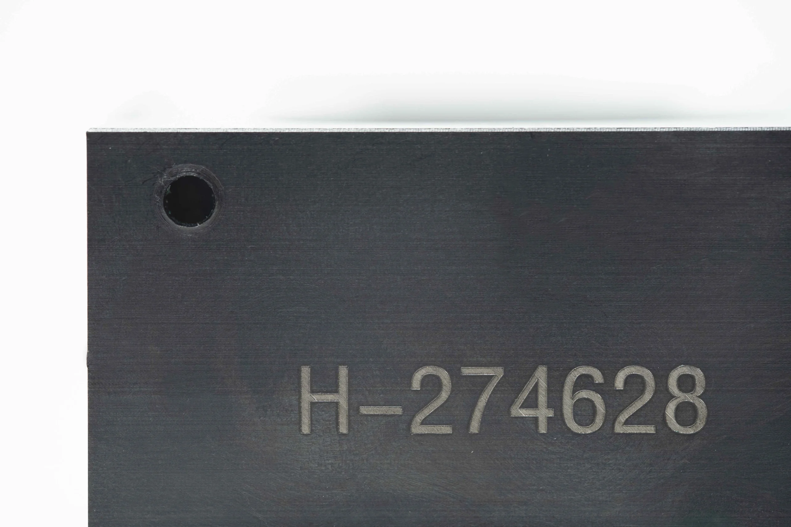
Identification Marking
Part numbers, revision identifiers, orientation marks, and position labels help operators install change parts consistently. Provide the marking content, location, method preference, and visibility requirements so identification does not compromise critical surfaces or inspection references.

Assembly Interfaces
Mounting faces, slots, nests, keyways, and mating features connect tooling to existing packaging equipment. Share interface drawings or models, datum strategy, allowable adjustment, and critical dimensions for a DFM review before production planning begins.
CNC Parts for Packaging Changeover Tooling
SUUXIANG is the sole public-facing brand of Dongguan SuuXiang Precision Mold Co., Ltd., established in 2010 in Chang’an Town, Dongguan, Guangdong, China. XiaoCheng Huang is the founder and legal representative. We help global teams turn drawings, models, material requirements, and quality expectations into inspected CNC parts, precision mold components, and tooling work.
For CNC parts for packaging changeover tooling, our planning brings together CNC milling and turning, multi-axis machining, EDM, precision grinding, fitting, and inspection as the drawing requires. Before quotation and production commitments, we review critical dimensions, datums, machining access, surface requirements, and the appropriate inspection approach.
What differentiates SUUXIANG is a controlled, drawing-led workflow. We focus project discussions on manufacturability, revision control, process sequence, and documented inspection needs so buyers can assess decisions before production begins. Submit an RFQ with the drawing, quantity, material, delivery target, and any quality or mating-component requirements.

CNC Parts for Packaging Changeover Tooling: Critical Dimensions to Inspection
DFM Starts at the Datum
SUUXIANG reviews the drawing before quotation to clarify functional datums, critical dimensions, mating relationships, tool access, and tolerance stack risks. This early discussion helps define a manufacturable route for CNC parts for packaging changeover tooling before production commitments are made.
- Identify locating faces, bores, pins, and reference features
- Review GD&T against assembly and adjustment requirements
- Flag thin walls, inaccessible features, and unstable setups
- Confirm drawing revision and applicable 3D model

Match Processes to Features
A change part may require more than milling or turning alone. SUUXIANG plans the appropriate combination of CNC machining, wire or sinker EDM, precision grinding, fitting, and inspection according to geometry, material condition, surface requirements, and the dimensions that govern repeatable installation.
- Use CNC machining for accessible profiles and primary forms
- Assess EDM needs for narrow slots, sharp internal forms, or difficult access
- Reserve grinding stock where flatness, parallelism, or fit requires it
- Sequence heat treatment and finishing around dimensional risk

Keep Revisions Visible
Packaging changeover tooling is often adjusted as formats, mating equipment, or operating feedback evolve. SUUXIANG keeps drawing revisions, clarified requirements, and production information visible throughout the project so the supplied part can be linked to the agreed technical definition and inspection plan.
- Confirm the current drawing revision before release
- Record agreed clarifications for critical features
- Separate superseded data from production-ready files
- Coordinate delivery information with the approved requirement

Inspect What Drives Fit
Inspection planning should focus on the dimensions that determine location, clearance, sealing, guiding, or interchangeability—not only a list of isolated measurements. SUUXIANG aligns the inspection method and final documentation with the order requirements and the features identified as critical during drawing review.
- Define critical-to-quality dimensions before machining begins
- Relate measurement points to functional datums
- Specify required reports or evidence in the RFQ
- Review surface and fit requirements alongside dimensions

CNC Parts for Packaging Changeover Tooling: A Controlled Workflow
Compare a drawing-led, evidence-based manufacturing workflow with quotation-only sourcing before production commitments.
← Swipe left or right to view →
CNC Parts for Packaging Changeover Tooling: Production Workflow
A controlled sequence aligns drawing intent, process planning, critical dimensions, inspection requirements, and delivery coordination before parts move into production.
Review Drawings and Requirements
SUUXIANG reviews 2D drawings, models, material, quantity, application context, critical dimensions, datums, surface requirements, inspection needs, revisions, and target delivery expectations.
Plan DFM and Process
The team evaluates machining access, tolerance stack, setup strategy, heat-treatment sequence, EDM requirements, grinding allowance, and suitable inspection methods before confirming the route.
Machine Critical Part Features
CNC milling, turning, multi-axis machining, or micro machining are applied as appropriate to create profiles, bores, threads, locating features, and mating interfaces.
Apply EDM and Grinding
Where geometry or finish requirements call for it, wire EDM, sinker EDM, precision grinding, and fitting support controlled feature completion and assembly-relevant relationships.
Inspect, Pack, Coordinate Delivery
Finished CNC parts for packaging changeover tooling are checked against the agreed inspection plan, documented as required, protected for shipment, and coordinated against the confirmed revision.
Order-Specific Quality Documentation for Packaging Changeover Tooling
Move from drawing review to controlled production with clear technical inputs, aligned expectations, and inspection documentation matched to the order.
Submit Your Technical Package
Send 2D drawings, 3D models, material requirements, quantities, target delivery dates, and application context so SUUXIANG can identify changeover interfaces and critical dimensions.
Review DFM and Quotation
Review datum strategy, tolerances, machining access, surface requirements, heat-treatment sequence, and inspection needs with our team before a process route and quotation are aligned.
Confirm First-Piece Expectations
Confirm sampling or first-piece expectations, including critical-feature checks, acceptance criteria, required reports, and revision status, before production commitments are released.
Coordinate Production and Inspection
Coordinate CNC machining, EDM, grinding, fitting, and planned inspection through controlled revision communication, then receive documentation matched to the agreed inspection plan.
Customer Evidence Publication Policy
Approved Results for CNC Parts for Packaging Changeover Tooling
Customer case study pending written approval. SUUXIANG will publish only attributable project outcomes supported by the customer and the applicable drawing, inspection, and delivery records.
Customer case study pending written approval. Published feedback will identify the relevant changeover-tooling application, reviewed critical dimensions, inspection scope, and verified outcome without disclosing confidential project details.
Customer case study pending written approval. SUUXIANG will add customer-approved evidence only after the attribution, performance result, and permission to publish have been confirmed.
CNC Parts for Packaging Changeover Tooling FAQ
Practical RFQ, inspection, material, revision, and delivery questions for drawing-driven changeover components.
What files should I send for cnc parts for packaging changeover tooling?
Is there a minimum order quantity for cnc parts for packaging changeover tooling?
Can I order samples of cnc parts for packaging changeover tooling before production?
How should I plan lead time for custom changeover tooling parts?
Which materials are suitable for packaging changeover tooling?
What inspection reports can be requested with an order?
How are design revisions, shipping, and IP handled?
Buyer’s Guide to cnc parts for packaging changeover tooling
Use this decision framework to specify fit-for-purpose change parts, compare materials and supplier controls, estimate cost drivers, and avoid drawing, validation, and changeover-design mistakes that create downtime.
1. What Are cnc parts for packaging changeover tooling?
1 format set is a drawing-defined group of CNC-machined components that lets one packaging machine run a different SKU, pack size, container shape, or product configuration. It is machine-specific tooling, not a general replacement part and not a complete packaging machine.
2 functional requirements govern each change part: establish repeatable position from defined datums, then guide or support the package through its assigned operation. Guides, pockets, rails, star wheels, locating plates, transfer elements, filling interfaces, sealing nests, and label-handling features may all change when the format changes.
3 questions should anchor the drawing review: what geometry, reference position, contact surface, and clearance must change for this SKU while mating reliably with the existing machine? The answer must preserve handoff timing, product control, package appearance, seal or fill consistency, and rapid return to stable production rather than merely making a part that fits.
2. Evolution of cnc parts for packaging changeover tooling
Four SMED steps reframed changeover work: tasks once performed after a line stopped were identified, prepared externally, and progressively simplified. Early format tooling was commonly a bolt-on assembly, positioned by operator adjustment and tightened one fastener at a time.
Two design changes shifted the requirement from a part to a system: positive location through pins, stops, and defined datums, plus standardized mounting and clamping interfaces. With a known seating condition, cnc parts for packaging changeover tooling can be installed as an interchangeable set instead of re-aligned by trial and error.
One documented setup method now matters as much as the machined geometry. Buyers should specify handling mass and grip points, interface datum relationships, matching-part identification, torque or clamp sequence, and inspection evidence; these controls make repeatability, ergonomic installation, and revision control verifiable across operators and production shifts. https://usersolutions.com/blog/smed-quick-changeover
3. Types of cnc parts for packaging changeover tooling
Six component families cover most format-dependent interfaces on a packaging line. For cnc parts for packaging changeover tooling, drawings must define both the machine datum scheme and product contact geometry.
Guides And Rails
Two guide faces control package tracking; edge radii and slot positions prevent scuffing. Provide rail section, mounting-hole pattern, conveyor datum, and package envelope.
Pockets, Star Wheels And Nests
One pocket profile indexes or supports each container; clearance, depth, and center pitch are critical. Provide product CAD, neck or body datum, rotation direction, and station pitch.
Change Plates And Format Sets
One change plate carries a repeatable machine interface across a format set; flatness and hole location govern interchangeability. Provide baseplate datum, fastener specification, and mating assembly drawing.
Sealing And Filling Interfaces
Two contact zones determine seal alignment or nozzle presentation; profile, concentricity, and cleanout access matter. Provide film or container geometry, process-side datum, and all wetted-area requirements.
Pushers And Transfer Parts
One pusher transfers packs between stations; stroke clearance, contact profile, and attachment stiffness affect handling. Provide motion path, pack orientation, drive connection, and interference envelope.
Locating And Clamping Hardware
Two locating pins establish repeatable position while clamps retain the format tooling; pin fit and clamp travel are critical. Provide datum callouts, receiver geometry, hardware standard, and operator access limits.
4. Materials for cnc parts for packaging changeover tooling
Material choice for cnc parts for packaging changeover tooling governs washdown life, operator handling, and replacement frequency. Select against the actual product, cleaning chemistry, contact condition, and duty cycle—not a generic machine-parts specification.
| Material | Best Fit | Key Trade-Off | Drawing Note |
|---|---|---|---|
| Aluminum alloy | Light fixtures | Lower wear resistance | Grade and finish |
| Stainless steel | Washdown parts | Higher handling mass | Grade and passivation |
| Engineering plastic | Package guides | Lower stiffness | Resin and contact requirement |
| Tool steel | Wear inserts | Corrosion risk | Hardness and treatment |
Match Material To Exposure
304 or 316 stainless steel suits wet, corrosion-sensitive locations; specify the cleaning agents and exposure interval.
6061 aluminum reduces lift mass for format rails and brackets, but requires a defined finish where cleanability or corrosion resistance matters.
Plan Wear And Contact
POM, UHMW-PE, and similar engineering plastics can protect packages on low-friction guides; identify abrasion, temperature, and product-contact limits.
Hardened tool steel is appropriate for repeated metal-on-metal wear; define hardness, heat-treatment sequence, and replacement criterion.
Document The Purchase Requirement
Each drawing should state material grade, approved substitutes, finish, and certificate or heat-lot traceability required.
Food-contact claims require the applicable market standard, contact duration, cleaning regime, and supporting declaration before manufacture.
5. Custom features and surface treatments
Repeatable cnc parts for packaging changeover tooling begin with controlled location, not faster fastening. Each interface should establish its datums before clamps apply force, preventing adjustment-driven variation between format sets.
| Feature | Changeover Function | Drawing Requirement |
|---|---|---|
| Locating pins | Repeatable position | Datum and fit |
| Keyway | Rotational orientation | Clocking direction |
| Identification mark | Format verification | Location and content |
| Surface treatment | Application-dependent protection | Process and masked areas |
Build A Datum Hierarchy
Three-point location commonly separates primary seating, secondary lateral location, and tertiary clocking. Specify datum features, pin fit, keyway orientation, and the surfaces that must remain free of coating buildup.
Prevent Incorrect Assembly
One asymmetric feature can distinguish otherwise similar format parts. Use poka-yoke profiles, unequal pin spacing, captive hardware, or quarter-turn fasteners only after confirming operator access, load path, and cleaning requirements.
Release Finish Requirements
Two controlled sources—a drawing and current 3D model—should identify revision, material, critical dimensions, surface finish, marks, and color code. Provide a labeled sample or mating-part context where visual orientation or functional fit cannot be fully conveyed.
6. Construction quality that protects uptime
Two parts can meet size limits yet still fight each other in assembly. SUUXIANG reviews functional datums and critical interfaces before selecting machining, grinding, EDM, and inspection steps for changeover tooling.
Functional Datum Strategy
Datum A should represent the machine seating face, while B and C locate motion or product-contact features. Specify GD&T for flatness, perpendicularity, concentricity, and true position relative to those datums—not isolated coordinate dimensions.
Three contact surfaces require equal attention: mounting face, locating feature, and mating interface. Burrs, broken edges, or unsuitable surface finish can prevent full seating and create jams or leakage despite acceptable measured sizes.
Inspection Before Release
First-article verification should inspect every critical-to-quality feature against the released drawing and revision. SUUXIANG can align the report, sampling approach, measurement method, and datum setup with the order’s inspection plan.
Gauge selection must reflect function: use pins or functional gauges for holes, thread gauges for tapped features, and appropriate metrology for form and position. Record the result with identifiable part and revision information.
Mating Part Trials
One trial assembly can expose tolerance-stack effects that separate measurements miss. Provide mating-part drawings, samples, clamp locations, seal interfaces, and any required fit class before manufacture.
Heat treatment and machining clamping can distort thin plates, long shafts, and closely positioned features. Plan roughing, stress relief where specified, finishing allowance, and final inspection after the relevant process stage.
7. How to choose a CNC changeover supplier
Two documents reveal more than a capability list: the controlled drawing and the supplier’s written response. Evaluate cnc parts for packaging changeover tooling against the actual assembly, not isolated dimensions.
| Evaluation Area | Evidence To Request | Decision Signal |
|---|---|---|
| DFM | Written risks and assumptions | Assembly-aware feedback |
| Quality | Sample inspection report | Critical features identified |
| Control | Revision workflow | Repeat-order consistency |
| Delivery | Lead-time basis | Capacity constraints visible |
Test Drawing Interpretation
1 drawing review should identify datums, mating interfaces, tolerance stacks, tool access, and adjustment features. Ask the supplier to state DFM risks before quoting.
2 examples of non-confidential comparable work can show whether the team understands assemblies rather than only individual features.
Verify Manufacturing Control
3 process questions should cover milling or turning route, material source, finishing coordination, and inspection method. Request a sample inspection report and a capability discussion tied to critical features.
4 traceability checkpoints should connect material, revision, inspection result, and shipment documentation.
Compare Commercial Discipline
5 quotation assumptions should list material condition, finish, tolerances, quantity, exclusions, and lead-time basis. Require a revision-control process from prototype through repeat orders.
6 communication checkpoints should define approval owners, change notices, inspection-report timing, and realistic delivery updates.
8. Common buyer mistakes with changeover parts
Two drawing-review failures cause most avoidable launch delays: an undefined datum scheme and absent mating dimensions. For cnc parts for packaging changeover tooling, release production only after the installed interface—not an isolated component—has been defined.
Define Interfaces Before Tolerances
Datum A must reflect the machine’s functional mounting face; arbitrary stock edges create setup ambiguity. Provide mating-hole locations, pin fits, centerlines, allowable adjustment, and a format-set assembly drawing before quotation.
A tolerance stack can consume clearance across plates, guides, and locators even when every part passes inspection. Assign critical dimensions to shared datums and review the worst-case stack with the supplier.
Specify Service Conditions First
Material and finish cannot be selected from appearance alone. State product contact, washdown chemistry, temperature, wear path, corrosion exposure, lubrication limits, and cleaning frequency before approving a coating or surface finish.
Operator reach, lifting load, hand clearance, fastener access, and error-proof orientation affect actual changeover time. Require an installation sequence or handling mock-up for parts changed manually.
Control Revisions And Validation
Revision changes sent by informal email can leave matched components manufactured to different versions. Issue a controlled drawing and model revision, record deviations, and require acknowledgement before machining.
One accepted part does not prove a working format set. Validate the complete installed set on representative machine interfaces, including locating, clamping, motion clearance, and the first production cycle.
9. Launching a new changeover format set
A format-set release starts with the actual pack, machine interfaces, and target changeover sequence—not a generic part list. Assign one controlled drawing package before any cnc parts for packaging changeover tooling are ordered.
Capture Inputs And Split Tasks
Engineering records pack dimensions, datum surfaces, machine stations, guarding limits, and mating hardware. Operations times each task and separates external preparation from machine-stopped work.
Quality defines critical fits, functional checks, and required records. Procurement confirms quantities, delivery milestones, and the approved revision with the machining supplier.
Review And Prove Critical Parts
The supplier reviews 2D drawings and 3D models for tool access, datum logic, material, finish, and inspection method. Engineering resolves ambiguities before release.
Critical guides, nests, locating pins, and change plates should be prototyped or first-article inspected. Operations trial-runs the set with production-representative packs while quality records fit, damage, and adjustment findings.
Standardize Release And Replenishment
A controlled setup sheet identifies sequence, torque or clamp settings, locations, and acceptance checks. Operations owns training and confirms the first repeatable changeover.
Each alteration receives a revision identifier, disposition for prior parts, and updated inspection criteria. Procurement replenishes only against the released revision; the supplier keeps drawing and inspection communication traceable.
10. Pricing cnc parts for packaging changeover tooling
Three quantity tiers make a comparable RFQ easier to evaluate: prototype, low-volume, and repeat-order. For cnc parts for packaging changeover tooling, the first article often carries programming, fixturing, tool selection, and first-article inspection effort that cannot be spread across many units.
Two parts with identical envelopes can quote very differently when material, deep pockets, thin walls, tight positional tolerances, multiple datums, EDM, grinding, deburring, finishing, or inspection reports change the process route. Consolidating related format-set components can reduce repeated setup and freight events, but only when revisions and material requirements are aligned.
Seven RFQ inputs support an apples-to-apples quote: 2D drawing, 3D model, quantity, material and heat treatment, critical dimensions, finish, and required inspection documentation. SUUXIANG should confirm the proposed route, exclusions, revision level, and delivery factors against the actual drawing before production is released.
| Quantity tier | Setup effort | Unit-cost tendency | Typical lead-time factors |
|---|---|---|---|
| Prototype: 1–5 pieces | Highest per part | Highest | Programming, fixtures, material availability, first-article checks |
| Low-volume: 6–50 pieces | Shared across batch | Falls as quantity rises | Setup reuse, machining time, secondary processes |
| Repeat order: established revision | Reduced if process is retained | Usually lowest | Material release, schedule, inspection scope, consolidated shipment |
Upload CNC Parts for Packaging Changeover Tooling Drawings
Include material, quantity, critical dimensions, quality requirements, target date, and mating-component context for a focused drawing review.