
CNC Machined Valve Spools, Reviewed Before Production
Send your drawing for DFM, critical-dimension review, process planning, and inspection requirements for cnc machined valve spools.
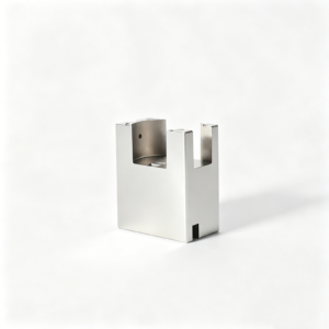
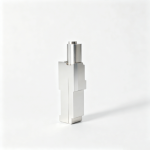
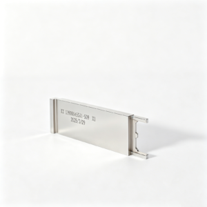
Representative Precision-Machined Components





Related Drawing-Based Component Families







Why Choose SUUXIANG for CNC Machined Valve Spools
Drawing-driven planning for critical valve-spool features, inspection expectations, and controlled project communication.
Drawing-Led DFM Review
We review datums, critical dimensions, machining access, and tolerance-stack risks before quotation so the process route reflects your drawing.
Process Route Planning
CNC turning, milling, EDM, grinding, heat treatment, and fitting are sequenced around geometry, stock allowance, and finishing requirements.
Critical Feature Focus
We identify spool lands, grooves, shoulders, bores, and metering edges that require defined controls before production planning begins.
Controlled Revision Handling
Drawings, models, inspection expectations, and delivery updates stay linked to the active revision, reducing avoidable manufacturing ambiguity.
Inspection Plan Alignment
Inspection methods and reporting needs are discussed against critical-to-quality features, helping align evidence with the order’s verified requirements.
Traceable Communication
Project communication keeps material questions, process decisions, dimensional priorities, and schedule changes visible from RFQ review through delivery.
Valve Spools and Precision Component Families
Drawing-driven machining, tooling components, and inspection planning for engineering teams managing fit, function, revision control, and delivery requirements.

CNC Machining Services
Precision CNC machining services for drawing-based valve spools, shafts, mold components, connector tooling, and custom parts. Reviews address material, datums, critical dimensions, tool access, process sequence, and inspection requirements before production commitments.
Upload a Drawing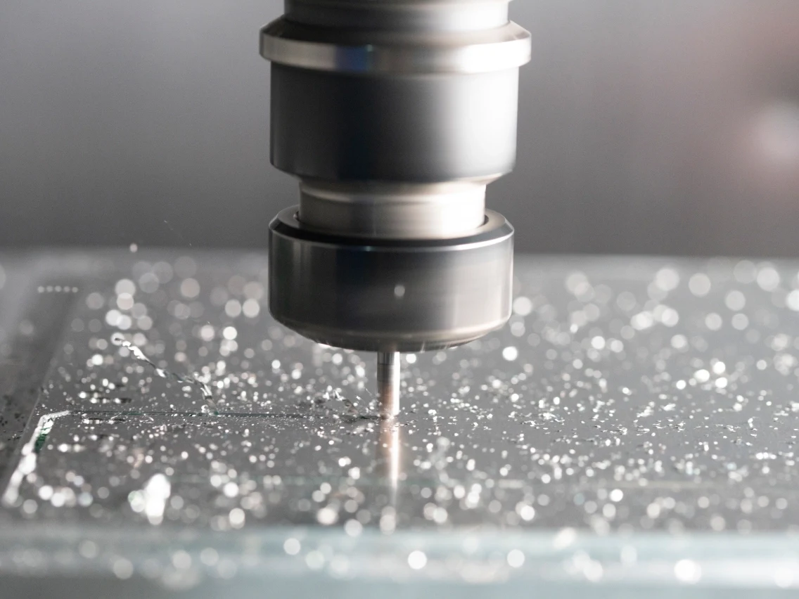
CNC Milling
Custom CNC milling services for prismatic and contoured components requiring controlled datum relationships, pockets, bores, sealing features, or mounting interfaces. Tool access, clamping strategy, machining allowance, and critical dimensions are reviewed against the drawing.
Upload a Drawing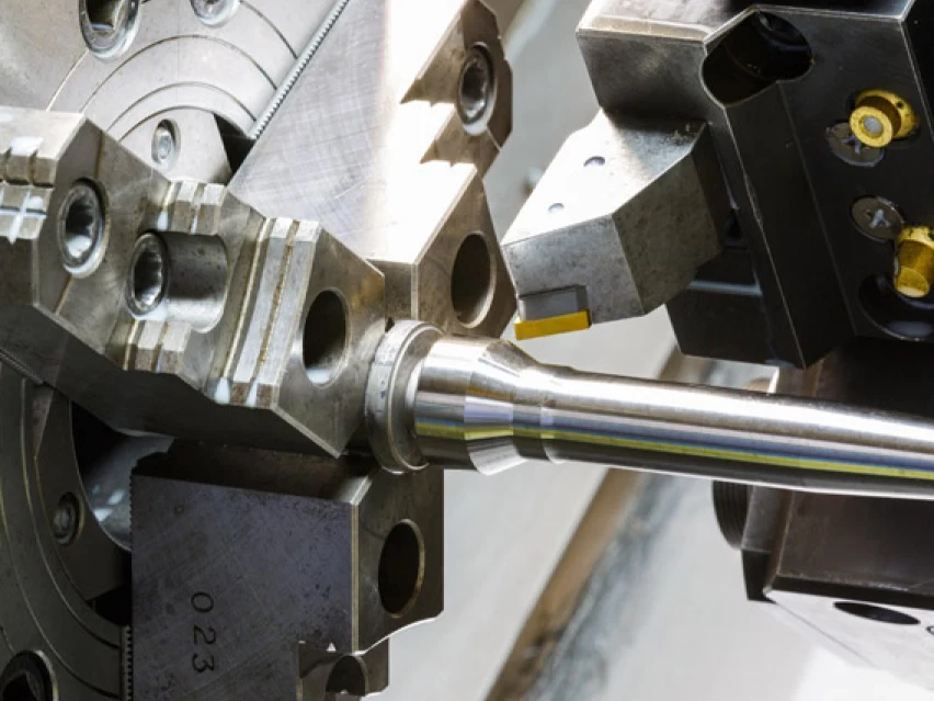
CNC Turning
Precision CNC turning services for rotational parts such as valve spools, precision shafts, sleeves, pins, and locating elements. The process route considers concentricity, runout, diameters, groove geometry, surface requirements, and downstream grinding or inspection needs.
Upload a Drawing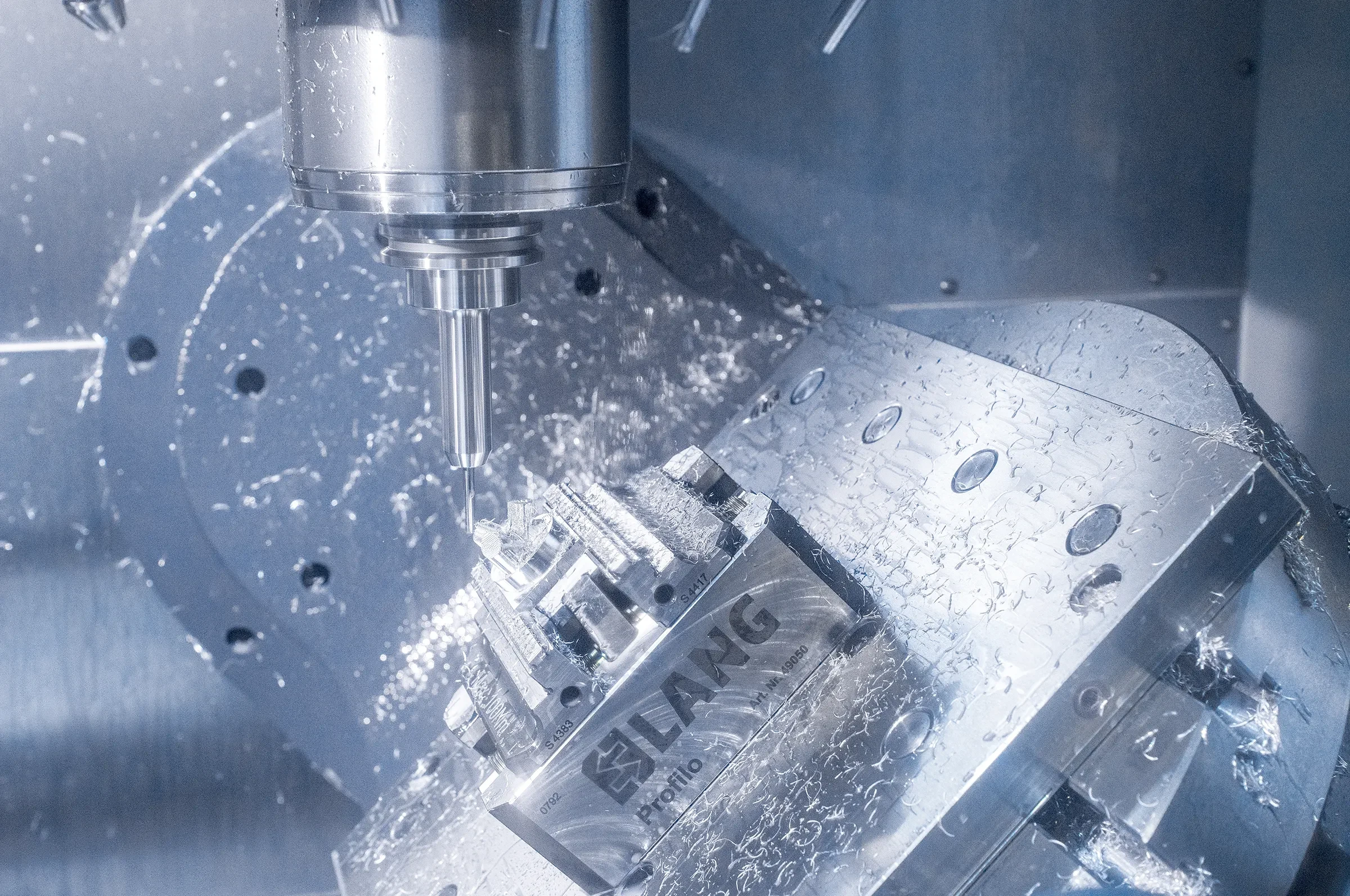
5-Axis Machining
5-axis CNC machining supports complex surfaces and multi-face features where fewer setups can help maintain relationships between critical features. Feasibility depends on geometry, tool reach, fixturing, material condition, tolerance priorities, and the verified inspection approach.
Upload a Drawing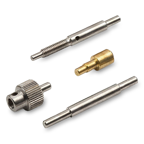
Swiss & Micro Machining
Swiss machining and micro machining support small, slender, and detail-intensive turned components, including pins, shafts, sleeves, and connector-related features. RFQs should identify small diameters, length-to-diameter ratios, burr limits, critical dimensions, material, and required inspection evidence.
Upload a Drawing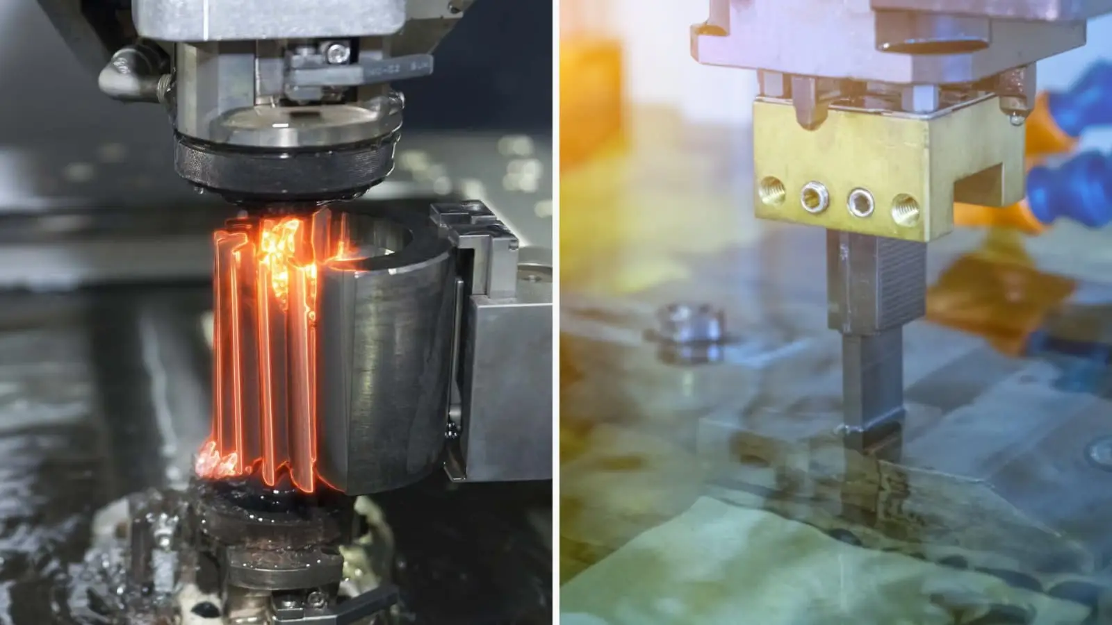
Wire & Sinker EDM
Wire EDM and sinker EDM services address hardened materials, fine profiles, sharp internal geometry, narrow slots, and difficult-to-machine mold features. Electrode strategy, wire path, flushing, recast-layer considerations, finishing allowance, and dimensional verification require project-specific review.
Upload a Drawing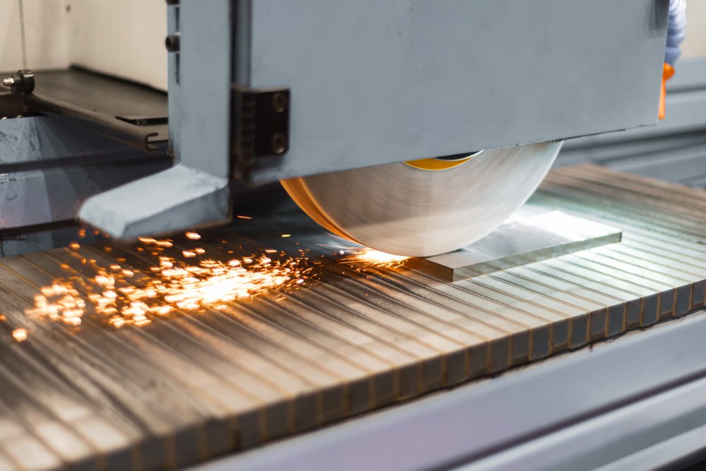
Precision Grinding
Precision surface and profile grinding is used where flatness, parallelism, profile control, finish, or fit relationships require a controlled finishing route. Drawings should define datums, grinding stock, heat-treatment condition, critical features, and inspection expectations.
Upload a Drawing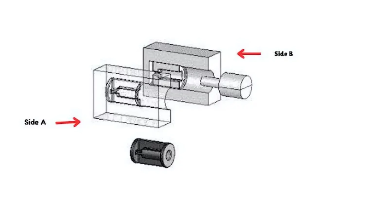
Mold Core & Cavity Inserts
Precision mold core and cavity inserts are produced as configurable components from approved drawings and 3D data. Manufacturing planning considers steel grade, heat-treatment sequence, cooling or feature access, EDM requirements, mating conditions, grinding allowance, and critical shutoff or forming surfaces.
Upload a Drawing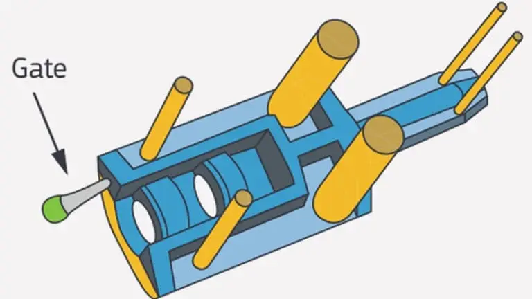
Ejector & Ejection Components
Ejector pins, sleeves, and ejection components are reviewed for fit, wear, motion, and assembly relationships within the mold. Define diameters, clearances, hardness requirements, surface condition, length tolerances, mating components, and any custom geometry before quotation.
Upload a Drawing
Core Pins, Guide & Locating Components
Core pins, guide pins, and locating components require attention to alignment, wear surfaces, press or slip fits, concentricity, and mating-part data. SUUXIANG evaluates the drawing-defined datum scheme, material condition, finishing route, and inspection method for the intended assembly.
Upload a Drawing
Slides, Lifters, Gates & Mold Accessories
Mold slides, lifters, gates, and accessories are supplied as drawing-defined component families rather than assumed standard catalog items. Reviews address travel interfaces, shutoff geometry, wear surfaces, lubrication provisions, heat-treatment sequence, fit-up, and the manufacturing route required by the design.
Upload a Drawing
Connector Mold Components
Precision connector mold components support tooling features where pitch, pin geometry, alignment, cavity relationships, and repeatable fit are decisive. Provide the relevant drawing set, mating-component context, material requirements, critical dimensions, and inspection or documentation needs.
Upload a Drawing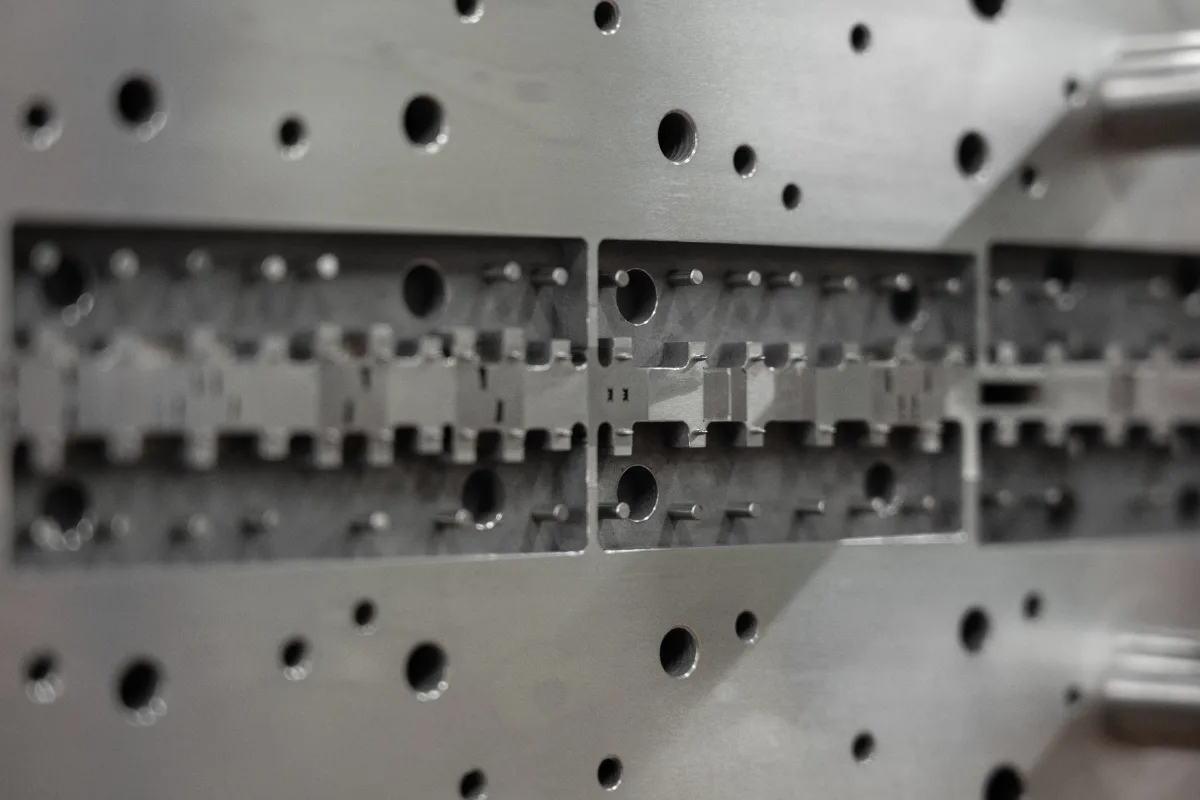
Stamping Die Components
Precision stamping die components are planned around drawing-defined cutting, forming, guiding, and locating functions. Material, hardness, edge condition, EDM or grinding requirements, clearance relationships, and mating die details should be exchanged before production planning.
Upload a Drawing
Injection, MIM, CIM & Overmolding Tooling
Injection, MIM, CIM, and overmolding tooling components are evaluated within SUUXIANG’s verified production scope. Technical review considers material behavior, mold-feature geometry, shutoff and parting conditions, inserts, ejection, thermal requirements, machining access, and component inspection needs.
Upload a Drawing
Machining Materials
CNC machining materials are selected against function, machinability, heat-treatment condition, corrosion exposure, wear requirements, and inspection priorities. Specify the material grade or approved equivalent, condition, traceability needs, and any material documentation required for the order.
Upload a Drawing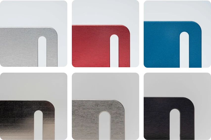
Surface Finishes & Heat Treatment
Surface finishing and heat treatment must be coordinated with dimensions, contact surfaces, corrosion or wear requirements, and final inspection. Identify required treatment, finish, masking or post-process constraints, hardness targets where applicable, and which dimensions are critical after processing.
Upload a Drawing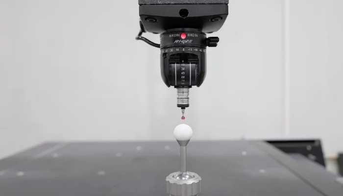
Quality, Metrology & Documentation
Precision inspection, metrology, and quality documentation are aligned to the drawing and an agreed inspection plan. Identify critical dimensions, datum references, measurement methods, sampling expectations, revision status, material records, and any report format required before manufacturing begins.
Upload a Drawing
Prototyping & Low-Volume Production
Rapid prototyping and low-volume manufacturing support drawing-based validation, bridge requirements, and controlled small-batch supply. An effective RFQ includes quantity, target date, application context, material, dimensional priorities, surface requirements, revision level, and inspection documentation needs.
Upload a DrawingMaterials for CNC Machined Valve Spools
Alloy Steel
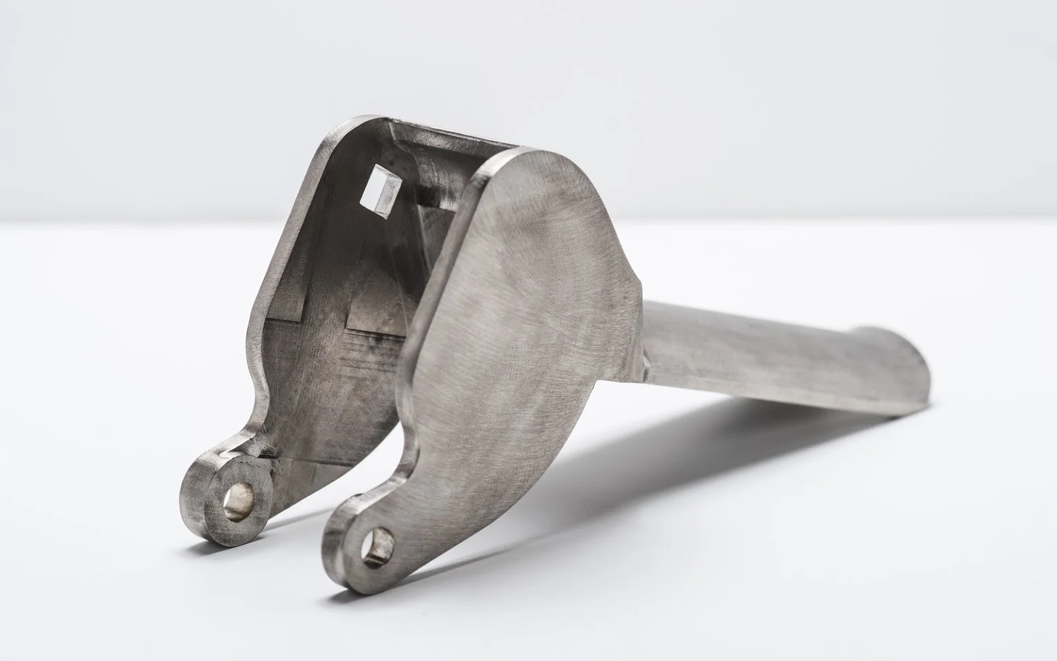
A robust choice for demanding hydraulic spool applications where strength and sliding-wear resistance matter. Heat-treatment sequence, grinding stock, coating allowance, and final datum control should be reviewed before production.
Stainless Steel
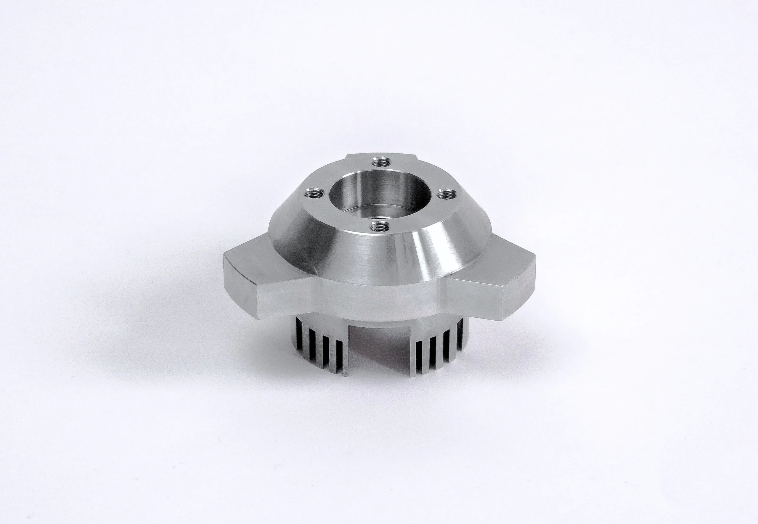
A corrosion-resistant option for spools exposed to moisture, chemicals, or aggressive fluids. Grade selection affects machinability, heat response, surface finish strategy, and the passivation or inspection requirements stated on the drawing.
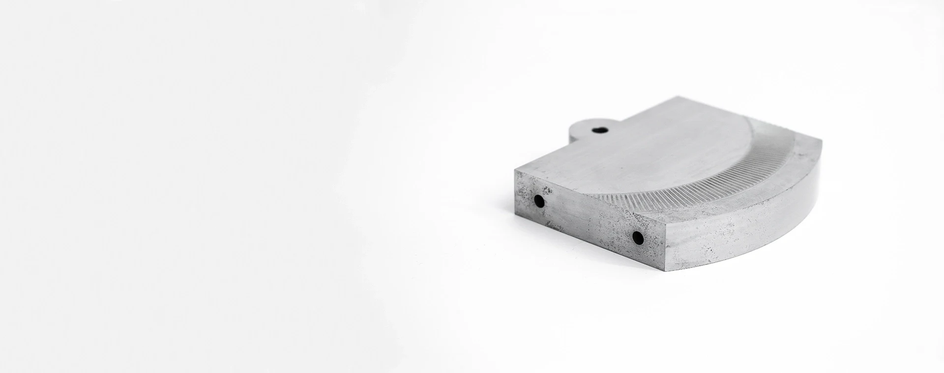
Tool Steel
A hard-wearing material suited to specialized valve designs requiring durable lands, grooves, or metering edges. Its functional character depends on the specified heat treatment, distortion allowance, grinding route, and critical-dimension plan.
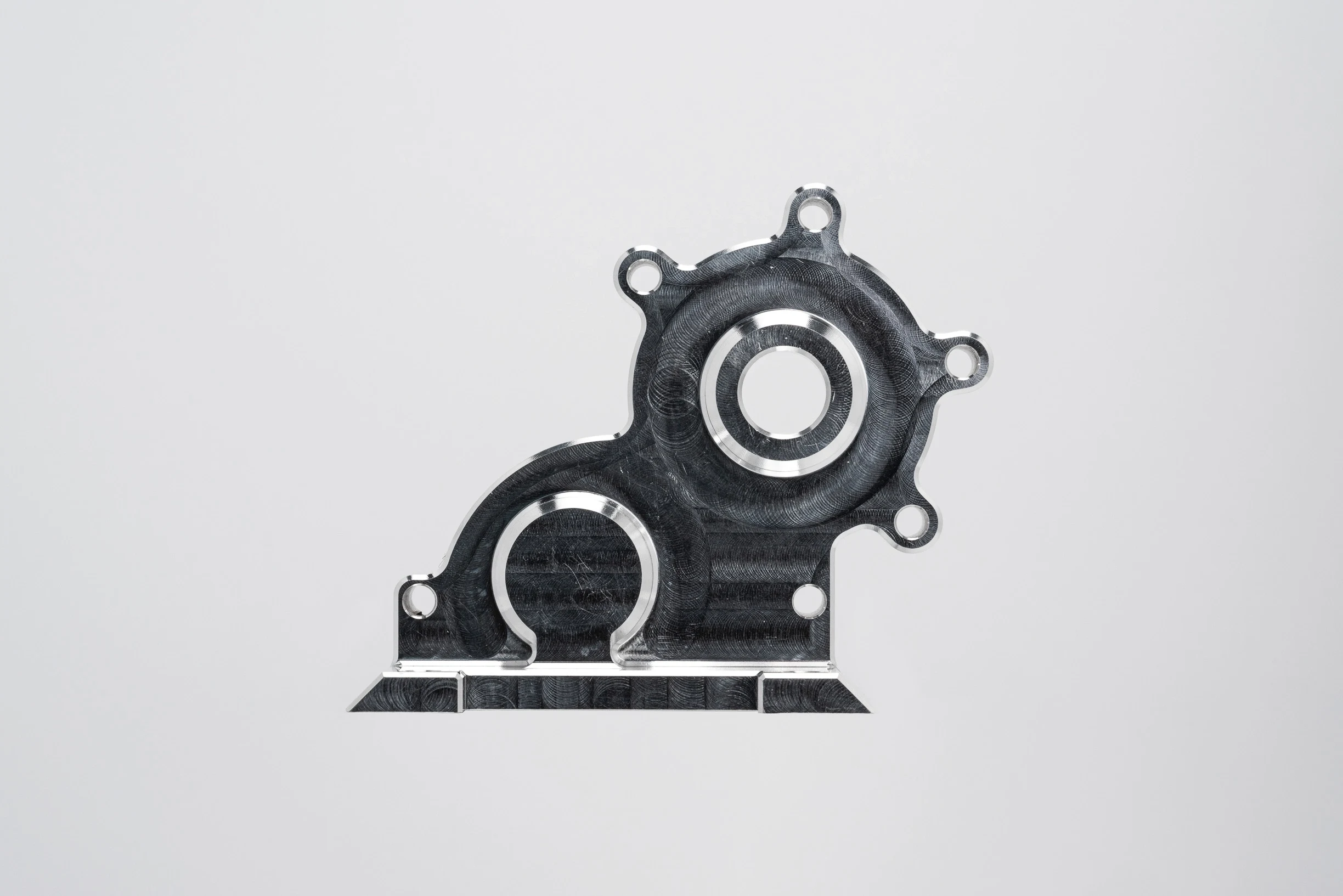
Aluminum Alloy
A lightweight option for pneumatic or specialized fluid-control assemblies where mass reduction is important. Alloy grade, anodizing needs, sealing interfaces, thread strength, and surface-finish expectations require drawing-based DFM review.
Prehardened Steel
A stable, production-friendly choice when the drawing calls for machining without a separate hardening cycle. Its practical benefit is reduced heat-treatment distortion, while tool access, groove geometry, and final inspection remain critical.
CNC Machined Valve Spools: Process Routes
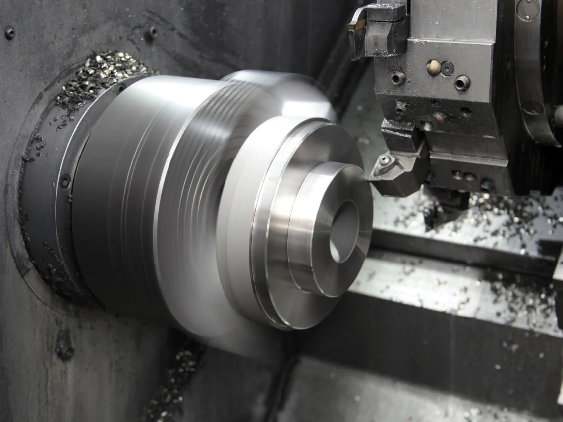
CNC Turning
Turning establishes rotational diameters, shoulders, lands, grooves, and end features. Setup strategy is reviewed against datum requirements, part rigidity, and the machining allowance needed for later finishing operations.
Feature Milling
Milling or live-tool machining can produce specified flats, slots, cross-holes, metering features, and locating details. Tool access, burr-control requirements, and feature-to-datum relationships should be confirmed during drawing review.
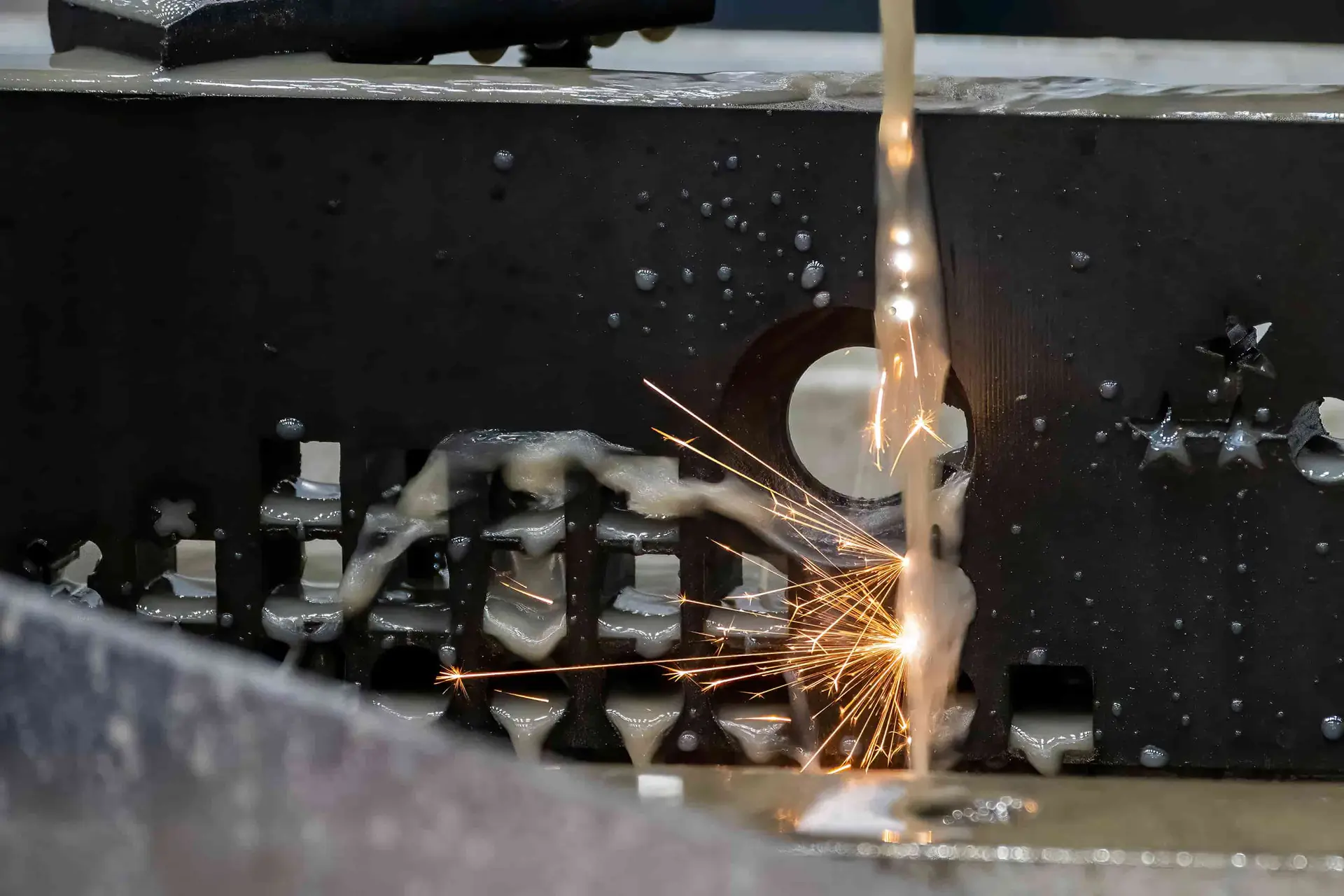
Wire EDM
Wire EDM is considered for profiles, narrow slots, and features where conventional tool access is limited. The wire path, start-hole requirements, corner conditions, and finishing allowance are evaluated against the drawing.
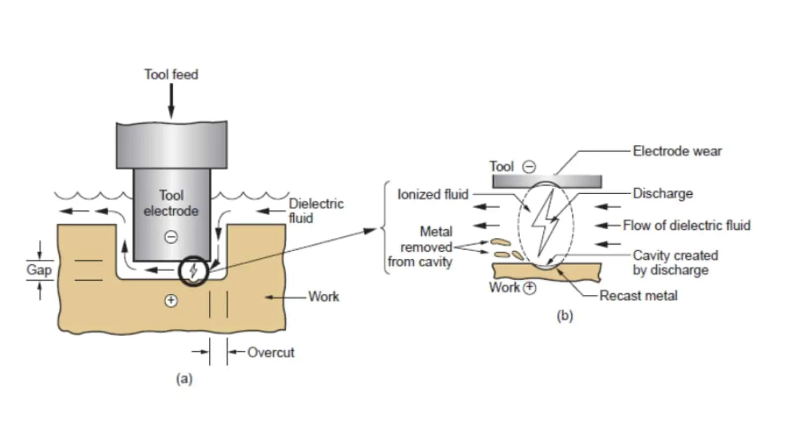
Sinker EDM
Sinker EDM can support formed cavities or difficult internal details when electrode access and geometry warrant the route. Electrode strategy, discharge finish, and any downstream polishing or fitting needs require project-specific review.
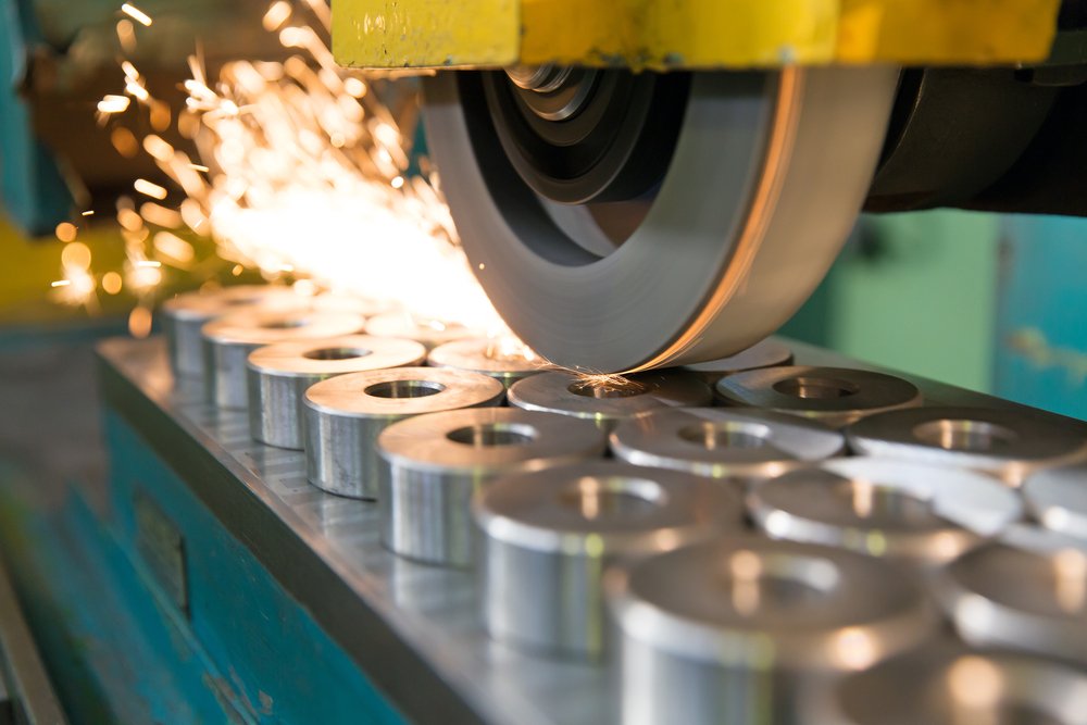
Precision Grinding
Grinding supports controlled final diameters, geometric relationships, and surface conditions after machining or heat treatment where applicable. Grinding stock, datum control, material condition, and inspection method must be defined before production.
Fitting Inspection
Fitting and inspection verify drawing-defined critical dimensions, interfaces, and documented requirements before release. SUUXIANG aligns measurement planning, revision control, and final reporting with the agreed order and inspection plan.
Functional Features for CNC Machined Valve Spools

Metering Grooves
Control grooves, lands, reliefs, and edge breaks can be planned around functional flow requirements. Provide geometry, datum references, surface priorities, and mating-bore context so the machining and inspection approach can be reviewed.
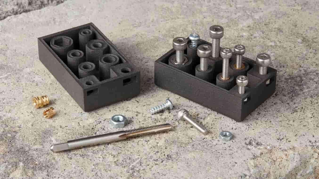
Threaded Features
Internal or external threads may support end connections, retainers, adjustment hardware, or assembly tooling. Identify thread standard, class, engagement length, runout expectations, and any post-treatment requirements before production planning begins.

Locating Details
Shoulders, pilot diameters, flats, keyways, and locating features help establish orientation and assembly position. SUUXIANG reviews their relationship to functional datums, tool access, concentricity needs, and the associated mating component.

Press-Fit Interfaces
Diameters intended for press fits require clear mating-part information, fit specification, material condition, and assembly direction. Drawing review can assess tolerance stack, chamfer requirements, surface condition, and inspection evidence needed for the interface.
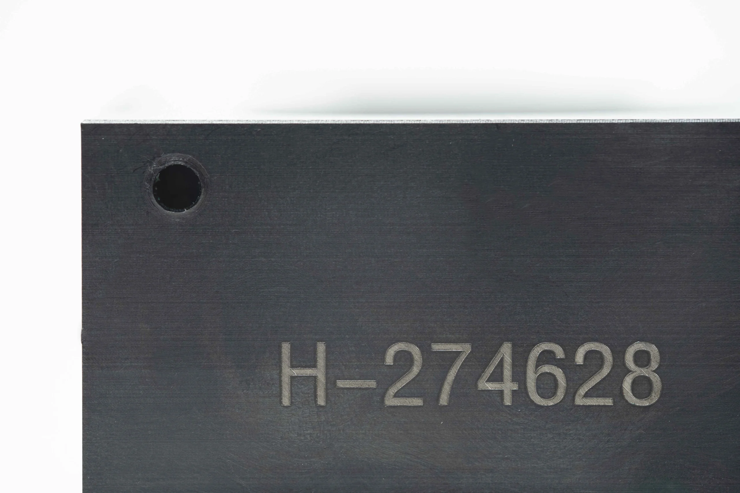
Part Marking
Laser marking, identification marks, revision codes, or traceability references can be considered where the drawing and surface condition permit. Define content, location, legibility expectations, and any restrictions on functional sealing or sliding surfaces.

Assembly Features
Cross holes, slots, retaining interfaces, wrench flats, and orientation marks may support installation or downstream assembly. Share application context and mating-part constraints so feature sequence, deburring access, and inspection requirements receive proper review.
About SUUXIANG
SUUXIANG is the sole public-facing brand of Dongguan SuuXiang Precision Mold Co., Ltd., established in 2010 in Chang’an Town, Dongguan, Guangdong, China. XiaoCheng Huang is the founder and legal representative. We help international engineering, sourcing, and quality teams turn drawings and specifications into inspected custom CNC parts, precision mold components, and connector-tooling work.
For cnc machined valve spools and related precision components, our process planning can combine CNC turning and milling, multi-axis machining, EDM, grinding, fitting and inspection. Each route begins with the drawing, material, quantity, application and quality requirements, so critical dimensions, datums, machining access and finishing needs can be reviewed before production commitments.
What distinguishes SUUXIANG is disciplined project communication around manufacturability and evidence. We work from the approved revision, identify tolerance-stack and machining-allowance risks, align the inspection method with the order, and keep delivery and revision information visible. Upload a drawing with your material, quality and delivery requirements to begin a focused review.

CNC Machined Valve Spools: Critical-Feature Planning
DFM and Datum Review
Before quotation, SUUXIANG reviews the drawing, model, mating context, and critical dimensions for CNC machined valve spools. The discussion identifies functional datums, tolerance-stack risks, tool access, and features that need a defined finishing or inspection route.
- Confirm functional datums and referenced surfaces
- Identify critical lands, grooves, edges, and cross-features
- Review wall sections, access limits, and clamping approach
- Align revision status before process commitments

CNC and EDM Strategy
Rotational features may suit turning or multi-axis machining, while windows, slots, and difficult internal geometry can require a separate EDM strategy. SUUXIANG plans the operation sequence around feature relationships, burr control, electrode access, and practical setup stability.
- Match turning, milling, and EDM to feature geometry
- Evaluate wire path or electrode access early
- Control setup changes that can affect feature alignment
- Define deburring needs for flow-control edges
Grinding Allowance Control
Where heat treatment or final surface requirements affect dimensional stability, machining allowance must be planned before production. SUUXIANG reviews stock for finishing operations so final diameters, concentric relationships, and working surfaces can be evaluated against the drawing requirements.
- Plan roughing and finishing sequence around heat treatment
- Reserve appropriate stock for grinding where needed
- Check datum continuity through finishing operations
- Review surface and geometric requirements together
Inspection Plan Alignment
An effective inspection plan connects the drawing’s critical dimensions to suitable measurement methods and order documentation. For CNC machined valve spools, SUUXIANG aligns inspection expectations, reporting needs, sampling requirements, and revision traceability before manufacturing proceeds.
- Identify critical-to-quality dimensions for reporting
- Match measurement methods to geometry and datum scheme
- Confirm required records with the RFQ or purchase order
- Keep drawing revisions and delivery information visible
CNC Machined Valve Spools: Supplier Evaluation Checklist
Use these criteria to confirm the engineering evidence, process planning, and documentation required before production begins.
← Swipe left or right to view →
Production Workflow for CNC Machined Valve Spools
A drawing-led route that aligns critical dimensions, process sequence, inspection evidence, and delivery requirements before production proceeds.
RFQ and Drawing Review
We review the 2D drawing, 3D model, material, quantity, application context, critical dimensions, surface requirements, reporting needs, and requested delivery date.
DFM and Process Planning
The team confirms datums, tolerance stack, tool access, groove geometry, machining allowance, heat-treatment sequence, and whether EDM or grinding is required.
Material and Setup Control
Approved material requirements and revision information are aligned before machining setup, helping keep the process route, inspection plan, and order requirements traceable.
Machining and Finishing
CNC turning, milling, multi-axis machining, wire EDM, sinker EDM, grinding, and fitting are combined as the drawing and verified process plan require.
Inspection and Documentation
Finished features are checked against the agreed inspection plan, with applicable dimensional records and order documentation prepared to match verified requirements.
Packing and Delivery Coordination
Parts are packed according to component protection needs, while delivery coordination and revision visibility remain aligned with the approved order and project schedule.
How to Work With SUUXIANG on CNC Machined Valve Spools
A drawing-driven engagement path that aligns manufacturability, critical dimensions, inspection expectations, and delivery documentation before production begins.
Submit Your Requirements
Send the 2D drawing, 3D model when available, material, heat treatment, quantity, critical dimensions, surface priorities, application context, inspection needs, and target delivery date.
Review DFM and Quotation
Review SUUXIANG feedback on datum strategy, tool access, machining sequence, EDM or grinding needs, inspection method, revision status, commercial scope, and quotation assumptions.
Confirm Production Details
Confirm the approved drawing revision, sample or production route, material and treatment requirements, quality documentation, acceptance criteria, packaging expectations, and delivery coordination before release.
Receive Parts and Records
Receive parts with delivery information and order-matched documentation aligned to the verified inspection plan, keeping revision control and traceability visible through final handoff.
Quality Documentation and Certification Evidence
Customer Feedback on CNC Machined Valve Spools
Approved, attributable customer feedback for CNC machined valve spools will be published when the customer, project scope, and measurable outcome can be confirmed.
SUUXIANG does not publish anonymous project claims or unverified performance results. Drawing review, inspection requirements, and delivery outcomes should be traceable to the approved order record.
For a relevant project reference, submit your drawing, material, quantity, and critical dimensions. SUUXIANG can discuss the applicable process route and inspection evidence for your requirement.
Project References Shared Only When Verified
Practical answers for engineering, sourcing, and quality teams preparing a drawing-based RFQ.
What is the minimum order quantity for cnc machined valve spools?
What drawings do you need to quote cnc machined valve spools?
Can you make cnc machined valve spools from a sample?
How long does a valve spool prototype take?
Which materials can be used for valve spools?
Can I request inspection reports for CNC machined valve spools?
How do you manage drawing revisions and protect project information?
What should I include in an RFQ for shipping and payment review?
The Complete Buyer’s Guide to cnc machined valve spools
Use a practical decision framework to define performance requirements, assess machining and inspection capability, compare supplier criteria, control cost drivers, and avoid drawing, material, finishing, and qualification mistakes before production.
1. What Are cnc machined valve spools?
One valve spool is the precision-moving member inside a valve body or sleeve. As it travels, it meters, opens, blocks, or redirects liquid or compressed-air flow between the valve’s ports.
Two basic features define its control action: lands and grooves. Lands are the raised cylindrical sealing and guiding bands; grooves are the reduced-diameter channels between them, while the metering edges at their boundaries progressively uncover or cover a port.
Three drawing relationships determine whether cnc machined valve spools suit the intended function: port layout, required stroke, and spool-to-bore fit. The outside diameter must slide freely in the matched bore while limiting unwanted leakage, and each land width, groove position, and edge geometry must correspond to the hydraulic or pneumatic circuit; otherwise, a different valve architecture or a matched spool-and-sleeve design may be required.
2. How cnc machined valve spools Evolved
3 manufacturing stages mark the shift from manually turned hydraulic control elements to cnc machined valve spools: basic turning established diameters and grooves, while skilled finishing compensated for variation. The result depended heavily on operator setup, gauging practice, and part-to-part judgment.
2 CNC-controlled operations—turning for features and grinding for final sliding diameters—made programmed geometry and repeatable sequences more practical. Grinding after hardening remains a common route because heat treatment can distort steel, and the process plan must reserve finishing stock (https://www.tuofamachining.com/news/valve-spool-cnc-machining-and-surface-treatment-for-precision-fluid-control-components-385205.html).
1 modern production expectation is closed-loop evidence, not merely a compliant sample: automated or in-process measurement can feed correction decisions, while documented inspection links results to the drawing revision. Buyers should now request datum definitions, measurement methods, finishing sequence, traceability level, and records for critical land, groove, and edge features before release.
3. Types of cnc machined valve spools
Cnc machined valve spools may share a cylindrical profile yet differ materially in lands, grooves, ports, and metering edges. Classifying the configuration first makes drawing review and process planning more reliable.
| Configuration | Defining Geometry | Typical Use | Key Drawing Input |
|---|---|---|---|
| Directional | Lands and control grooves | Port switching | Stroke and timing |
| Proportional | Tapers or notches | Variable flow | Metering profile |
| Cartridge | Compact stepped form | Screw-in valve | Seals and threads |
| Multi-land | Repeated lands | Multiple flow paths | Angular features |
Directional-Control Spools
Two or more lands alternately connect or block body ports during axial travel. The drawing should define land widths, groove spacing, stroke positions, and port timing relative to a common datum.
Proportional Spools
Tapered, notched, or profiled metering edges change flow progressively with displacement. Edge profile, angular orientation, transition radii, and the required flow-versus-stroke relationship require explicit definition.
Cartridge Spools
Compact cartridge designs combine functional lands within a short envelope that mates to a bore or sleeve. Thread details, sealing grooves, cross-holes, and datum references can drive setup count and inspection access.
Multi-Land And Custom Metering
Four or more lands can coordinate several flow paths, while custom windows or grooves tune a specific response. Provide unfolded angular locations, groove-bottom radii, burr limits, and any mating sleeve information before quotation.
4. Materials and Heat Treatment Choices
Four material families cover most cnc machined valve spools decisions: pressure, fluid chemistry, corrosion exposure, mass, and sliding wear must be evaluated together. A drawing review should name the mating bore, duty cycle, and required hardness before stock is released.
| Material Family | Advantages | Constraints | Selection Considerations |
|---|---|---|---|
| Alloy steel | Strength and hardenability | Corrosion protection may be needed | High-pressure hydraulic duty |
| Stainless steel | Corrosion resistance | Grade-dependent wear performance | Moisture or aggressive fluids |
| Tool steel | High hardness and wear resistance | Hard machining; treatment distortion | Severe sliding wear |
| Aluminum alloy | Low mass and machinability | Lower hardness and wear resistance | Lightweight pneumatic duty |
Material Selection Matrix
Three selection questions prevent a nominally strong material from becoming a poor sliding pair: what fluid contacts it, what load acts at the land, and what finishing route is feasible.
Treatment Sequence And Geometry
Two-stage routing—rough machining, controlled heat treatment, then grinding or hard finishing—reserves stock for distortion correction. Specify hardness zone, datum surfaces, grinding allowance, and final inspection method on the drawing.
5. Surface Finishes for cnc machined valve spools
Surface finish is a functional specification for cnc machined valve spools, not a cosmetic choice. The mating bore, fluid, seal material, hardness, and required clearance determine the finishing route.
| Route | Primary Use | Drawing Control |
|---|---|---|
| Finish turning | Profile and stock control | Stock allowance, Ra |
| Grinding | Final diameter and geometry | Ra, roundness, cylindricity |
| Polishing or superfinishing | Texture refinement | Ra, measurement direction |
| Coating or treatment | Wear or corrosion need | Buildup, final dimension |
Select The Finishing Route
Turning can establish profile and leave controlled stock; grinding commonly corrects hardened diameters and geometry. Hard turning, polishing, or superfinishing should be evaluated against material condition, land geometry, and the specified functional surface.
Control Functional Surfaces
Low roughness alone does not ensure stable sliding. Roundness, cylindricity, taper, and burr-free metering edges affect bore contact, leakage paths, seal wear, and the risk of sticking.
Coatings and treatments add thickness and can alter fit or edge form. Specify the permitted buildup, post-treatment finishing route, and whether dimensions apply before or after treatment.
Call Out Inspection Clearly
Each critical land should identify the Ra requirement, cutoff or applicable drawing standard, measurement direction, and sampled locations. State the instrument or accepted measurement method for diameter, roundness, cylindricity, and edge condition.
Acceptance criteria should define datum references, inspection quantity, reporting format, and treatment certification where required. SUUXIANG can review these requirements against the drawing and proposed process route before production.
6. Critical Construction and Quality Elements
Two dimensions can share a nominal tolerance yet behave differently in service. For cnc machined valve spools, the drawing review should identify every critical-to-function feature before the inspection plan is released.
Lands And Metering Edges
Land diameter governs the functional relationship with the mating bore, while groove width, depth, spacing, and metering-edge form govern port timing and flow transitions. Define edge breaks explicitly; an unspecified deburr operation can alter a sharp functional edge.
Datums And Geometric Controls
Concentricity, straightness, and runout are geometric requirements, not substitutes for nominal diameter tolerances. Establish a datum axis, datum faces, and the mating sleeve or body requirements so inspection references the same functional setup as assembly.
Holes, Burrs, And Cleanliness
Cross holes require review for drill access, breakout location, intersection burrs, and cleaning access. Specify the permitted burr condition and cleanliness expectation, then match gauges, visual checks, and cleaning verification to the risk of blocked passages or damaged mating surfaces.
7. How to Choose a Spool Manufacturer
Choose a supplier by testing its control plan against the drawing, not by comparing a generic capability list. For cnc machined valve spools, require evidence that process decisions follow the functional datums and mating-bore requirements.
| Evaluation Area | Question To Ask | Evidence To Review |
|---|---|---|
| Metrology | How are form and location measured? | Inspection plan and report |
| Traceability | Can material and special-process lots be linked? | Lot records and certificates |
| Packaging | How are precision surfaces protected? | Packaging specification |
| Communication | Who controls revisions and delivery changes? | Change log and response path |
Drawing Review And DFM
Before quotation, ask for a written review of critical diameters, land edges, grooves, datums, runout, and surface callouts.
Ask which dimensions require turning, grinding, EDM, or post-treatment finishing, and how distortion allowance will be protected.
- Identify CTQ dimensions and inspection method
- Request revision-controlled DFM feedback
- Confirm mating-part assumptions
Process And Material Control
For each material grade, request the proposed machining and heat-treatment sequence, including final-stock allowance and hardness verification.
When plating, nitriding, coating, or heat treatment is outsourced, ask who approves the supplier, records the lot, and verifies post-process dimensions.
Quality Continuity
At first article, require dimensional results tied to drawing revision, measurement equipment, sampling scope, and nonconformance disposition.
For prototype-to-low-volume transfer, ask whether the same route, fixtures, special-process source, packaging method, and traceability rules will remain controlled.
8. Common cnc machined valve spools Sourcing Mistakes
Drawing-based sourcing fails when functional interfaces are left implicit. For cnc machined valve spools, convert every performance assumption into controlled drawing data and an inspection requirement before release.
Define The Sliding Fit
One nominal spool diameter cannot define leakage or sliding behavior; taper, roundness, land length, and datum location may remain uncontrolled.
Two mating-bore details must accompany the RFQ: actual bore tolerance and finish, plus the intended clearance or selective-fit strategy. Require the supplier to review the spool and sleeve drawings together.
Plan Material And Heat Treatment
One lowest-cost material choice can undermine wear, corrosion, or hardness needs and can change the machining route.
Two stages should be specified: material condition before machining and required heat treatment afterward. Reserve grinding stock, define final dimensions after treatment, and request a distortion-control and inspection plan.
Specify Finish, Cleanliness, And Validation
One vague note such as smooth finish leaves roughness direction, metering-edge condition, burr limits, and cleaning acceptance open to interpretation.
Two controls prevent assembly surprises: call out the surface requirement by feature and define deburring, flushing, and packaging expectations. Qualify more than one sample by checking repeatability across a pilot lot and documenting the revision, gauges, and results.
9. Steps From Drawing Review to Production
Two controlled gates prevent an RFQ from becoming an uncontrolled build: technical agreement and production release. For cnc machined valve spools, the drawing package, mating-bore context, and revision level must remain linked throughout both gates.
Align Critical Characteristics
Before routing, engineering identifies land diameters, groove geometry, datums, surface requirements, and inspection methods. Any unclear tolerance, datum conflict, or missing mating condition stops release for buyer clarification.
Confirm Route And DFM
After material and heat-treatment requirements are confirmed, the supplier proposes turning, milling, EDM, grinding, and finishing allowances. Tool access, distortion risk, burr control, and measurement access require written disposition before sampling.
Approve Evidence Before Release
At Gate 2, the buyer approves samples or first-article evidence against the agreed inspection plan. SUUXIANG then releases controlled production with traceable records; drawing, material, process, tolerance, coating, or inspection changes trigger revalidation.
10. Pricing and Cost Drivers
1 drawing-specific quotation begins with the released revision, annual or lot quantity, material condition, and the mating-bore requirements. cnc machined valve spools cost more when lands, metering edges, cross-holes, or slender geometry require extra setups, specialized workholding, EDM, grinding, or controlled deburring.
2 quotation assumptions should identify critical dimensions, datum references, surface callouts, heat-treatment sequence, coating stock, inspection method, report format, and packaging. Request a drawing-specific quote from SUUXIANG and confirm whether material certificates, first-article evidence, and qualification documentation are included.
| Quantity tier | Setup burden and process route | Inspection/documentation | Relative cost effect | Typical lead-time effect |
|---|---|---|---|---|
| 1–5 prototypes | Programming, custom holding, turning plus milling or EDM | Critical-feature report | Highest unit cost | Longer review and setup |
| 10–50 pieces | Setup spread across a small batch; grinding may remain | Sampling or full critical checks | Moderate unit cost | Stable after first-piece approval |
| 50+ repeat pieces | Validated routing and reusable holding | Defined sampling plan | Lower setup cost per unit | Scheduling improves with forecast |
| Hardened/coated parts | Heat treat, finish grinding, or coating allowance | Pre/post-process verification | Adds process and risk cost | Adds external-process coordination |
| Tight geometry | Fine grinding, EDM, superfinish, or burr control | Expanded dimensional records | Raises inspection and yield cost | Adds measurement and rework reserve |
Upload Your CNC Machined Valve Spool Drawing
Include 2D and 3D files, material, quantity, critical dimensions, inspection requirements, and target delivery date for a disciplined drawing review.