
CNC Parts for Motor Test Benches From Your Drawings
SUUXIANG reviews DFM, critical dimensions and process routes for CNC parts for motor test benches before quotation and production planning.
Representative Components for Drawing-Led Manufacturing





Related Configurable Component Families


CNC Parts for Motor Test Benches: Drawing-Led Advantages
Plan critical interfaces, process routes, inspection evidence and revisions before production begins.
DFM Before Quotation
Drawing review identifies tool access, datum intent, tolerance risks and process questions before pricing or production commitments are made.
Critical Dimensions Planned
CTQ features, mating interfaces and surface priorities can be aligned with practical inspection methods and reporting expectations.
Coordinated Process Routes
CNC machining, EDM and grinding are sequenced around geometry, heat-treatment needs, machining allowance and finishing access.
Inspection Built In
Inspection planning connects drawing requirements to datums, measurement methods, acceptance criteria and order-specific documentation.
Revision Visibility
Controlled communication keeps drawing revisions, open technical questions, production status and delivery requirements visible throughout the project.
Precision Parts for Motor Test Benches
Drawing-driven CNC, tooling and inspection workflows for configurable components supporting fixtures, interfaces, housings and production equipment.

CNC Machining Services
Precision CNC machining services for drawing-based test-bench brackets, housings, adapters, shafts and fixtures. Process planning reviews datums, critical dimensions, material requirements and inspection needs before production commitments.
Upload a Drawing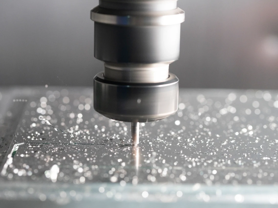
CNC Milling
Custom CNC milling services for structural plates, motor mounts, fixture bases, manifolds and complex prismatic components. Tool access, clamping strategy, feature depth and tolerance relationships are reviewed against the supplied drawing.
Upload a Drawing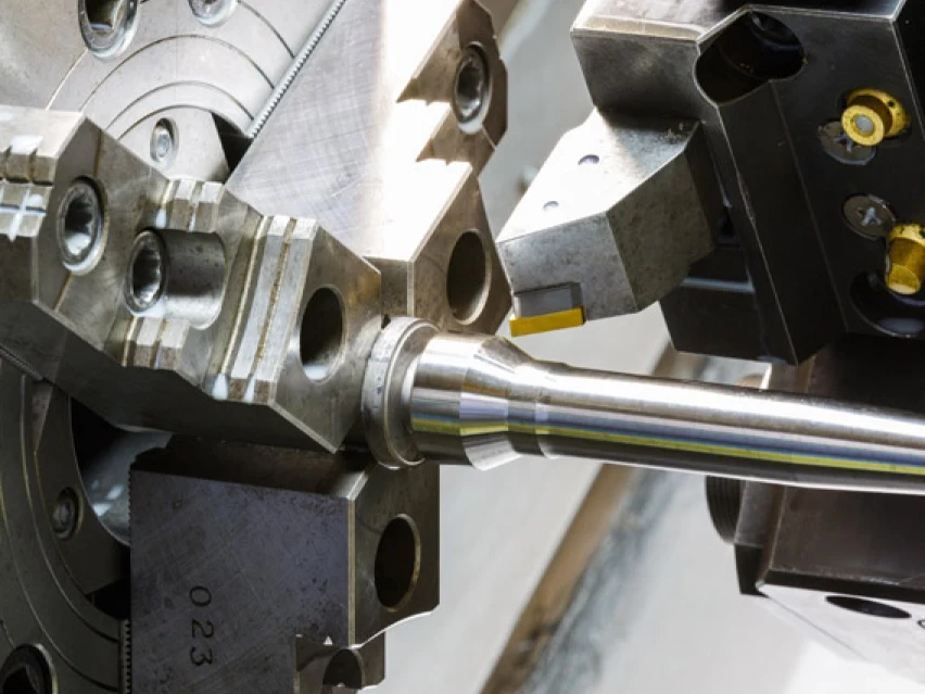
CNC Turning
Precision CNC turning services for rotational components such as shafts, bushings, collars, spacers, sleeves and threaded adapters. Drawings should define datum surfaces, runout priorities, thread requirements and mating-part context.
Upload a Drawing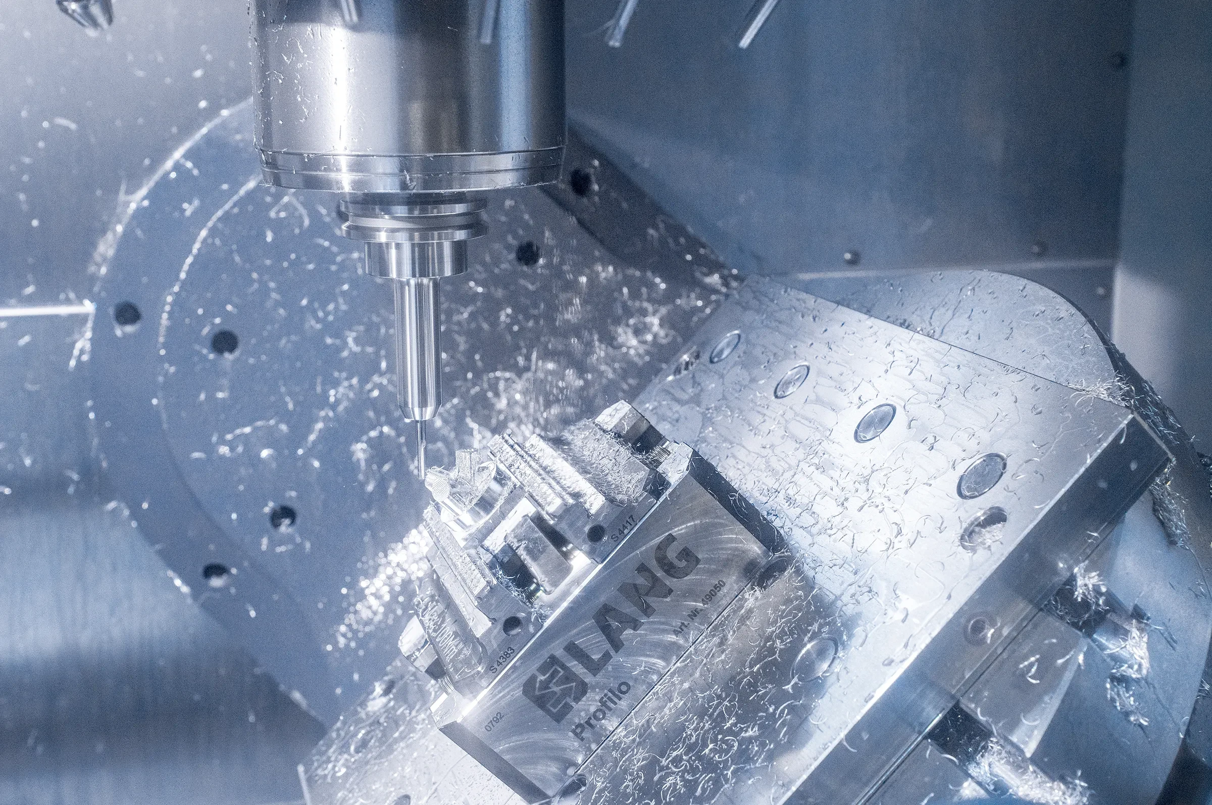
5-Axis Machining
5-axis CNC machining supports parts with angled features, compound surfaces and multiple critical faces that benefit from fewer setups. Feasibility depends on geometry, tool reach, material condition, tolerance requirements and inspection access.
Upload a Drawing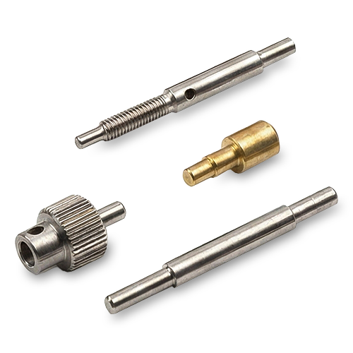
Swiss & Micro Machining
Swiss machining and micro machining support small, high-detail turned components where concentric features, slender geometries and controlled handling matter. Submit part dimensions, material, quantity, surface requirements and functional interfaces for review.
Upload a Drawing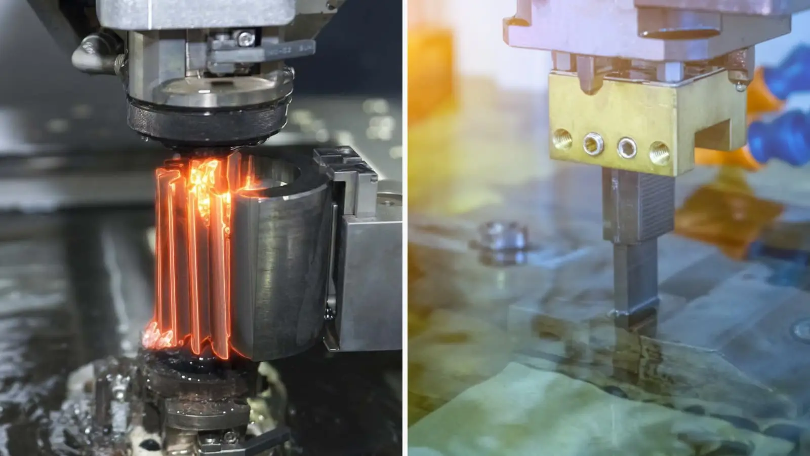
Wire & Sinker EDM
Wire EDM and sinker EDM services address hardened features, narrow slots, internal corners, precision profiles and geometry that conventional tools cannot reach efficiently. Electrode strategy, wire path, finish requirements and post-EDM inspection are planned from the drawing.
Upload a Drawing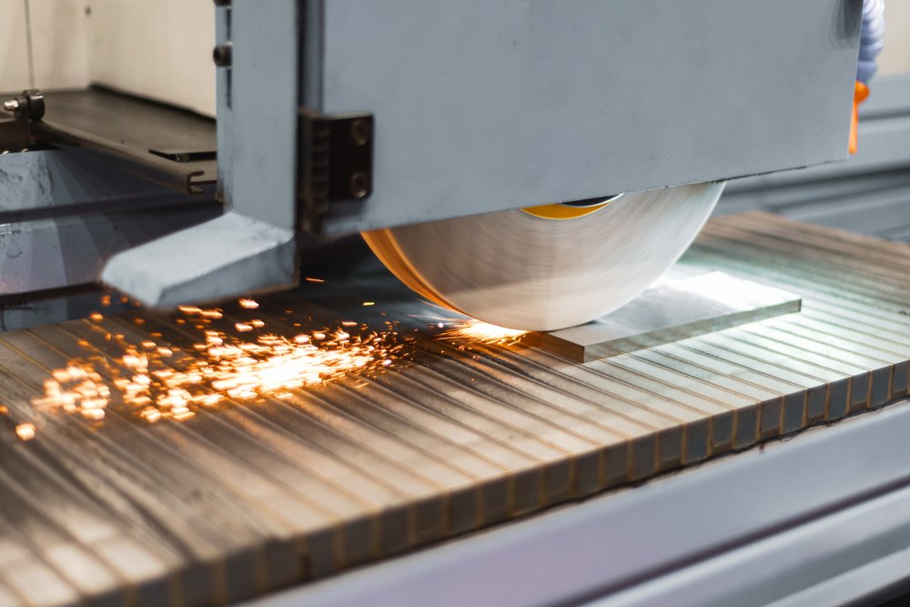
Precision Grinding
Precision surface and profile grinding supports controlled flatness, parallelism, profile accuracy and finish on critical interfaces. Grinding stock, heat-treatment sequence, datum strategy and measurement method should be confirmed before machining begins.
Upload a Drawing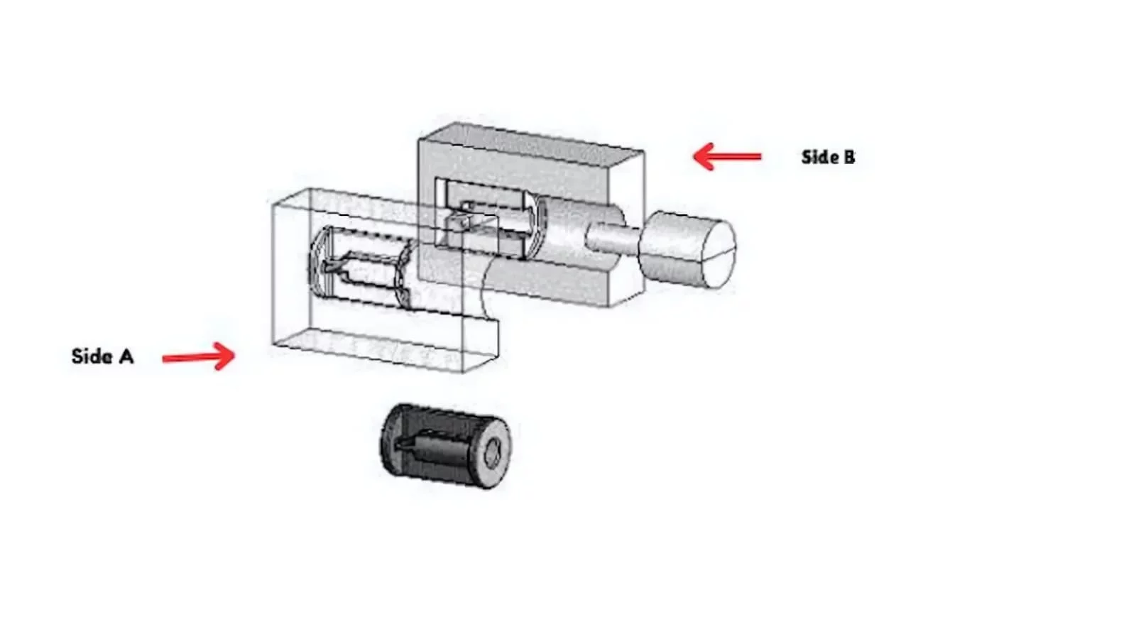
Mold Core & Cavity Inserts
Precision mold core and cavity inserts are manufactured as configurable tooling components from customer drawings and 3D data. CNC, EDM, grinding and fitting routes are selected around detail geometry, steel condition, cooling features and critical shutoff areas.
Upload a Drawing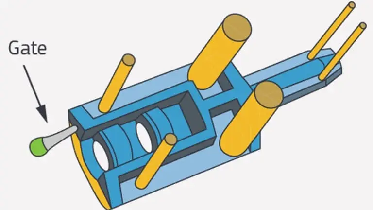
Ejector & Ejection Components
Ejector pins, sleeves and ejection components are produced to drawing-defined dimensions and functional fit requirements. Specify material, hardness or heat-treatment requirements, bearing surfaces, clearance relationships and any mating ejector-system details.
Upload a Drawing
Core Pins, Guide & Locating Components
Core pins, guide pins and locating components require careful control of functional diameter, concentricity, seating surfaces and wear conditions. Drawing review identifies datum relationships, material and treatment sequence, grinding requirements and inspection priorities.
Upload a Drawing
Slides, Lifters, Gates & Mold Accessories
Mold slides, lifters, gates and accessories are configurable components requiring coordinated geometry, fit and motion considerations. Provide assembly context, contact surfaces, travel requirements, material condition and critical interfaces for manufacturability review.
Upload a Drawing
Connector Mold Components
Precision connector mold components support tooling features where pitch, cavity detail, alignment and repeatable mating geometry are consequential. SUUXIANG reviews drawing data, electrode needs, EDM access, grinding stages and inspection expectations before release.
Upload a Drawing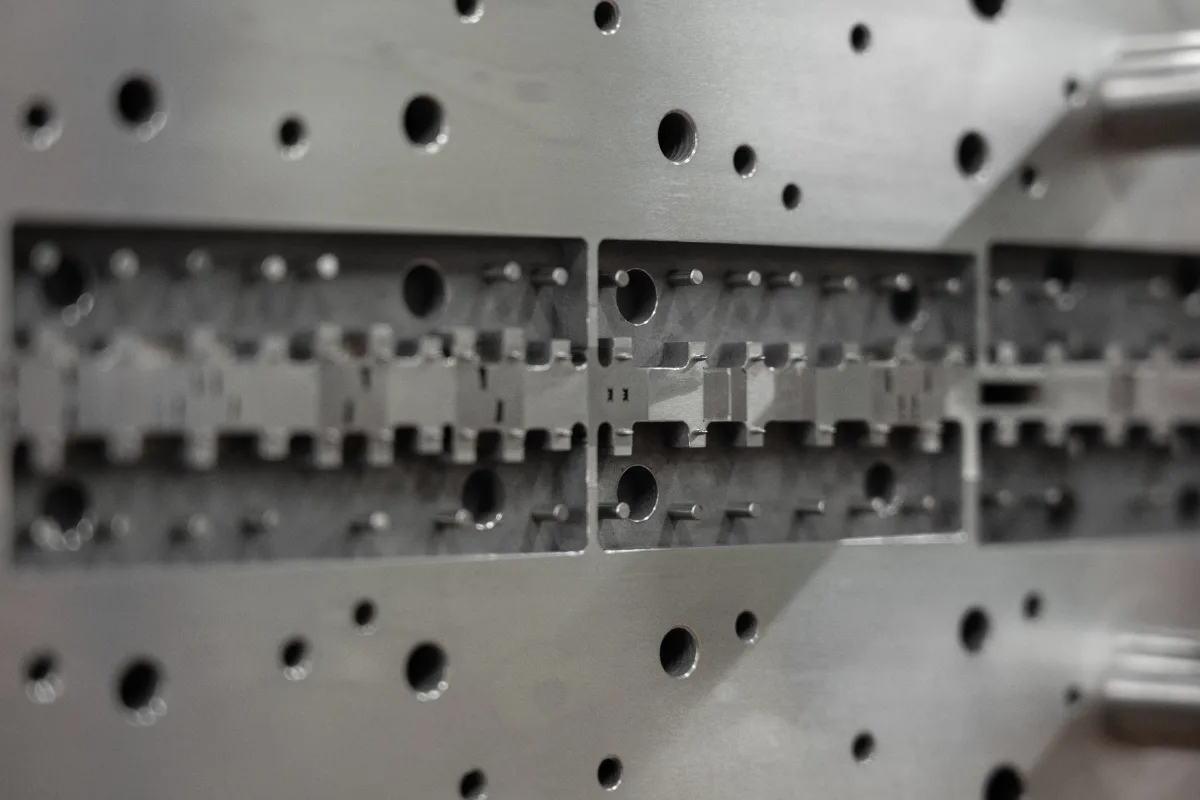
Stamping Die Components
Precision stamping die components are made from drawings for die sets, punches, inserts, guides and related forming-tool elements. Material, heat treatment, clearance relationships, cutting edges and assembly datums must be defined for route planning.
Upload a Drawing
Injection, MIM, CIM & Overmolding Tooling
Injection mold components and tooling for MIM, CIM and overmolding are evaluated within verified production scope. Requirements should identify resin or feedstock context, part geometry, insert interfaces, gating considerations, shrinkage assumptions and required tooling evidence.
Upload a Drawing
Machining Materials
CNC machining materials are selected from the drawing and application requirements, considering machinability, strength, corrosion exposure, wear, heat treatment and dimensional stability. Confirm the specified grade, material condition and any traceability expectations with the RFQ.
Upload a Drawing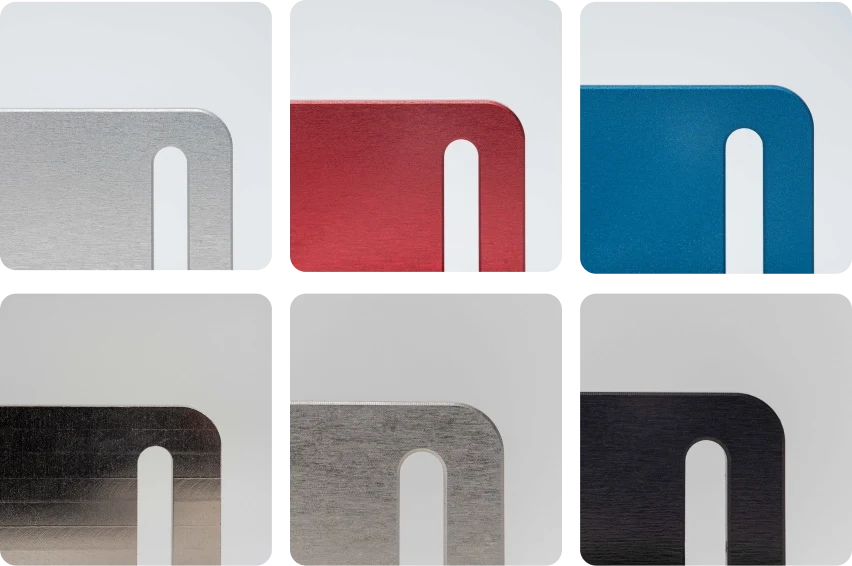
Surface Finishes & Heat Treatment
Surface finishing and heat treatment are planned around function, material and dimensional priorities. State coating or finish requirements, target hardness where applicable, masking needs, cosmetic surfaces, post-treatment stock and inspection criteria.
Upload a Drawing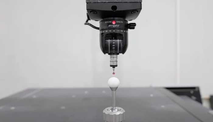
Quality, Metrology & Documentation
Precision inspection, metrology and quality documentation are aligned to the order and verified inspection plan. Identify critical dimensions, datum scheme, reporting format, sampling expectations, material records and revision-controlled drawing requirements.
Upload a Drawing
Prototyping & Low-Volume Production
Rapid prototyping and low-volume manufacturing support controlled evaluation builds, replacement components and pre-production tooling work. Submit drawings, quantities, required delivery date, material, critical dimensions and inspection needs so the process route can be assessed.
Upload a DrawingMaterials for CNC Parts for Motor Test Benches
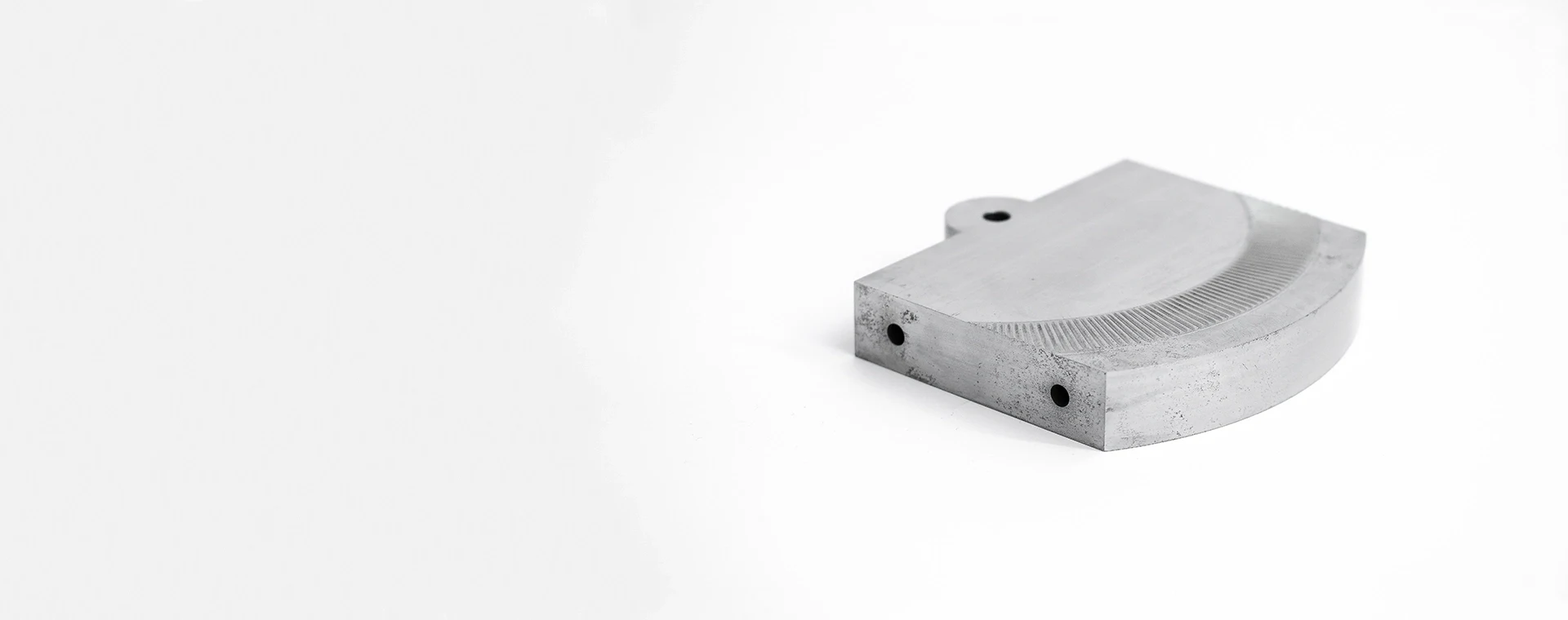
Aluminum Alloys
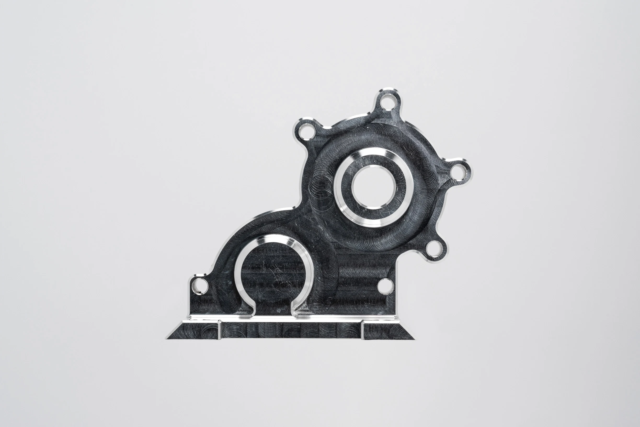
Lightweight and easy to machine, aluminum alloys are commonly specified for fixture plates, brackets, covers and instrument mounts. Grade, temper, wall stiffness and surface treatment should be confirmed where flatness, corrosion exposure or threaded interfaces matter.
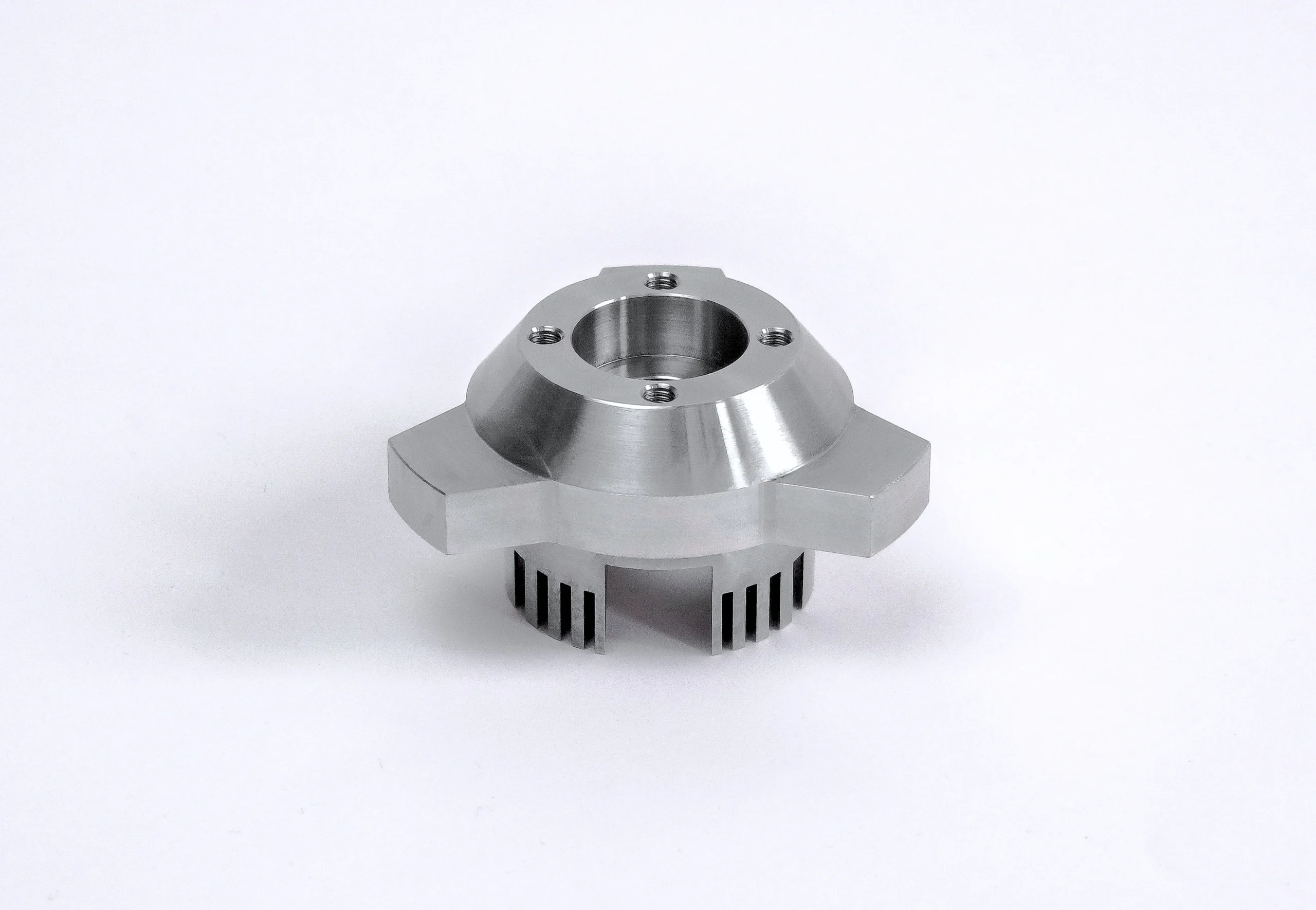
Alloy Tool Steels
Rigid and wear-resistant after the specified heat-treatment route, alloy tool steels suit shafts, locating features, load-bearing adapters and durable fixture elements. Machining allowance, hardness target, grinding stock and inspection datums require review before manufacturing.
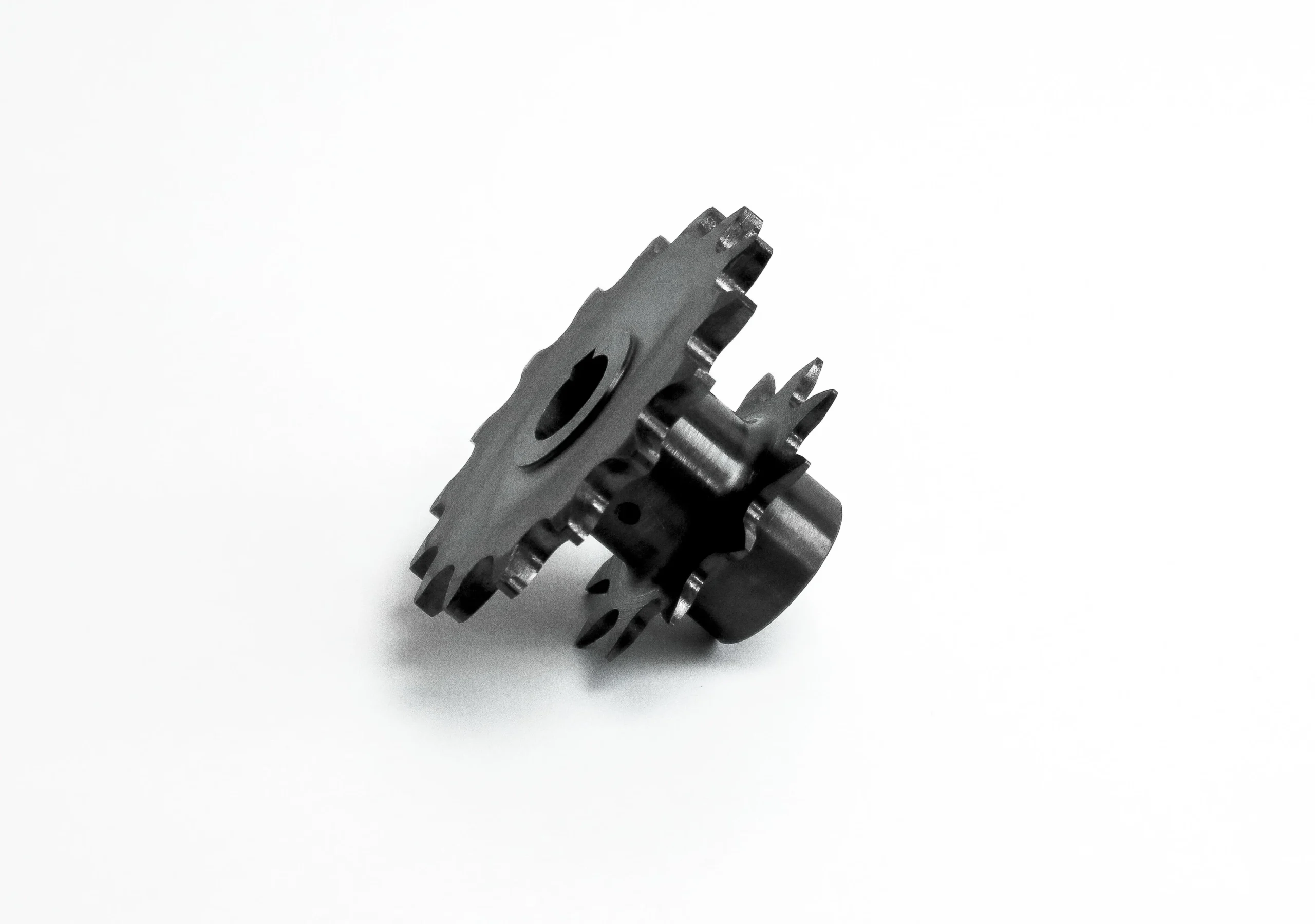
Stainless Steels
Stainless steel provides a clean, corrosion-resistant material option for mounts, guards, adapters and components used around fluids or humid environments. The selected grade affects machinability, magnetic behavior, strength and finishing approach, so drawing requirements should govern.
Carbon Steel Grades
Carbon steel offers practical strength and economical use for base structures, brackets, spacers and non-corrosive-duty interfaces. Specify the grade, stock condition, coating requirement and critical machined surfaces so process planning can account for distortion and protection.
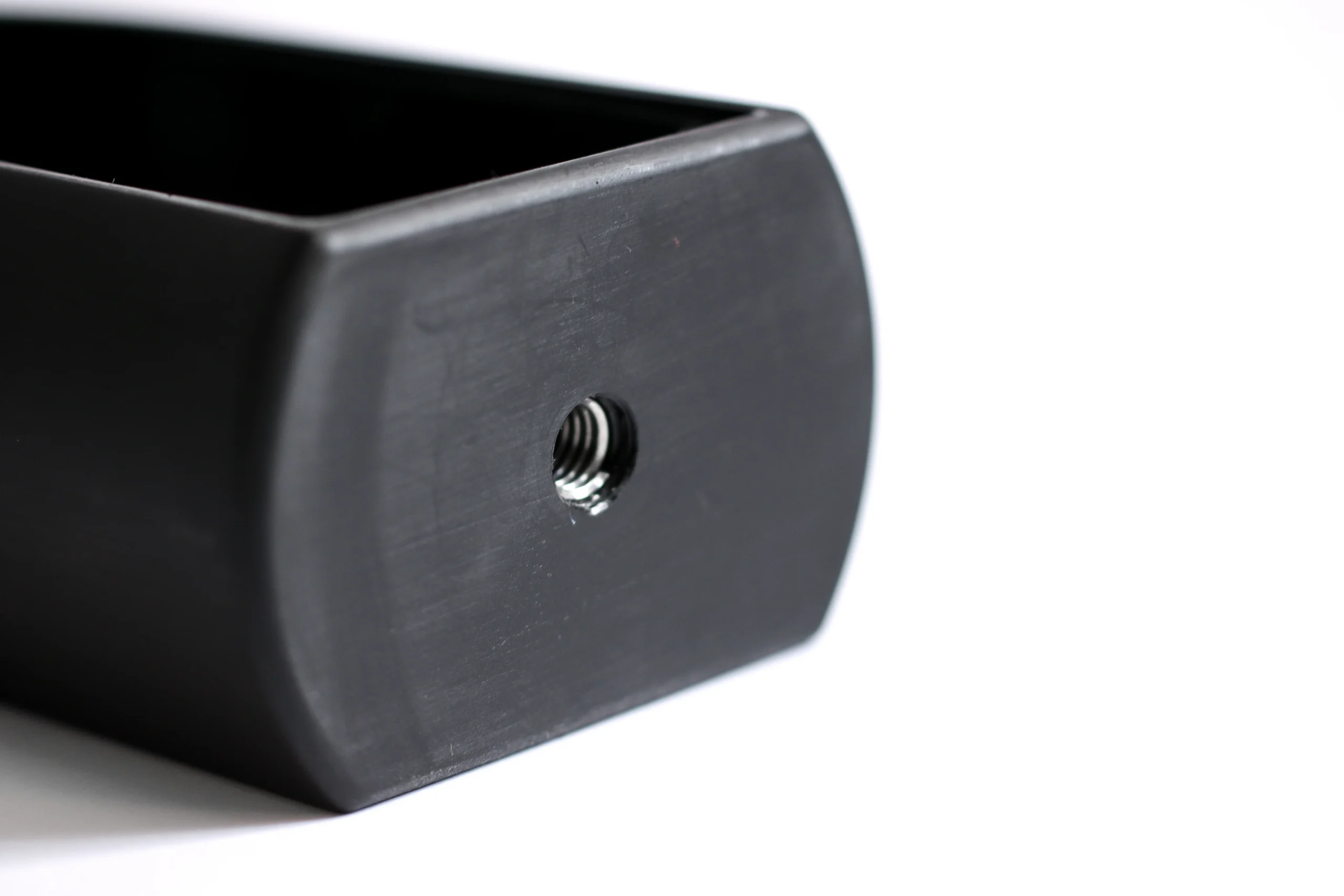
Engineering Plastics
Low-friction, electrically insulating engineering plastics can suit protective guides, sensor interfaces, wear pads and non-load-critical spacers. Confirm the resin grade, temperature exposure, dimensional stability and fastening method because these factors influence machining and fit.
CNC Parts for Motor Test Benches: Process Routes
CNC Milling
Milling produces mounting plates, housings, brackets and structural features from drawing-defined stock. Tool access, datum locations and clamping strategy are reviewed to protect critical interfaces and support practical inspection.
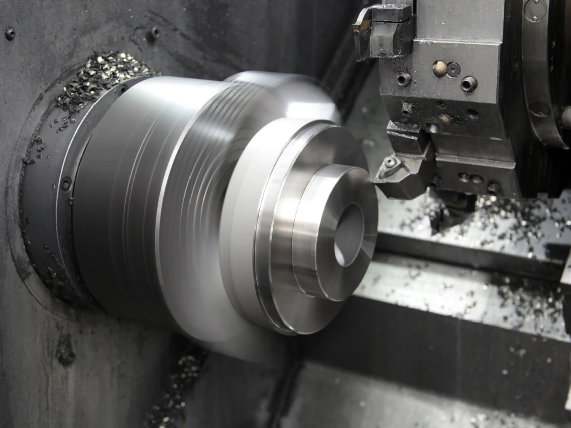
CNC Turning
Turning supports shafts, adapters, bushings and other rotational parts where concentricity and diameter relationships matter. Process planning considers workholding, material condition, finishing allowance and the dimensions requiring verification.
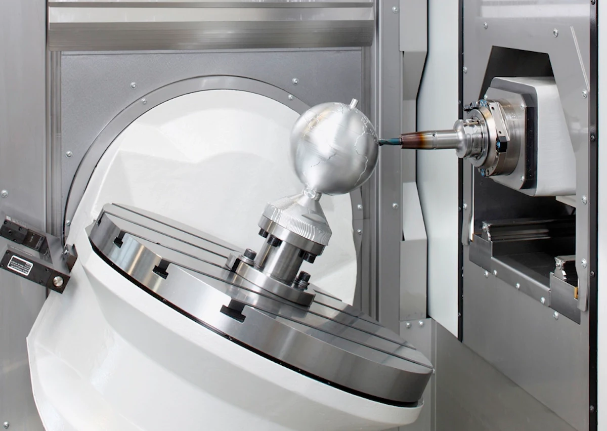
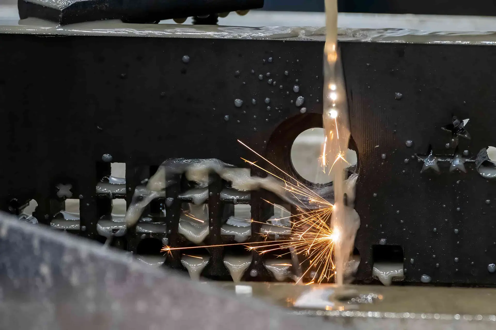
Wire EDM
Wire EDM is considered for precise through-profiles, narrow slots and hardened features when conventional tool access is limited. Wire path, start-hole location, corner requirements and finish expectations should be defined during review.
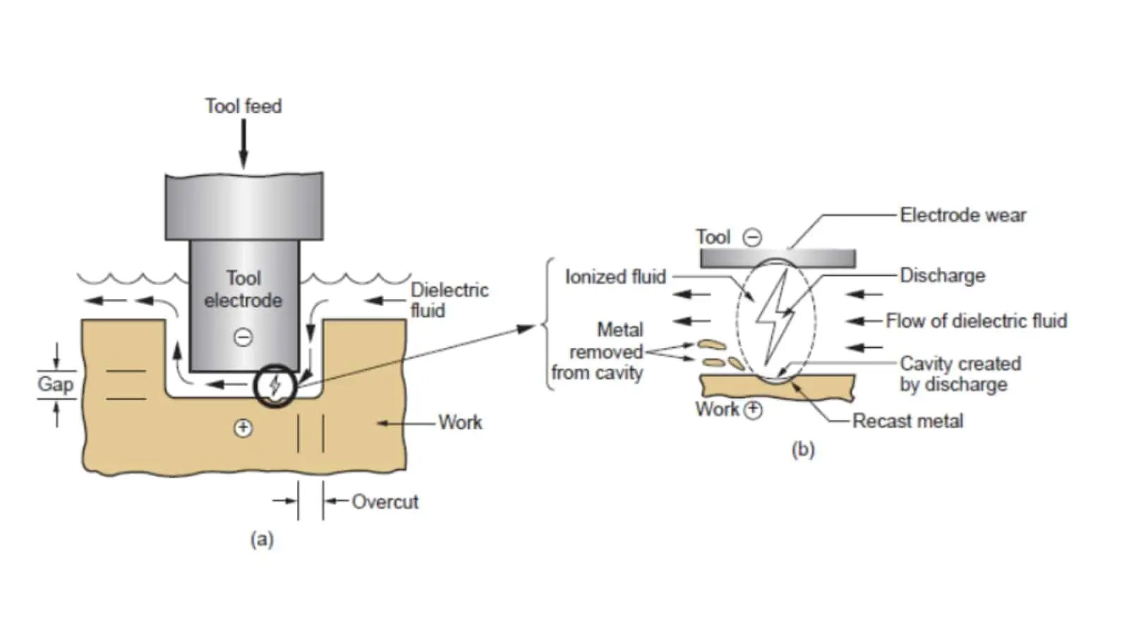
Sinker EDM
Sinker EDM forms deep cavities, sharp internal details and complex features using planned electrodes. Electrode strategy, spark allowance, material hardness and downstream finishing requirements are evaluated against the approved drawing.

Precision Grinding
Precision grinding refines critical flatness, parallelism, diameter or surface requirements after suitable machining stages. Grinding stock, heat-treatment sequence, datum control and inspection method must align before production planning.
Hardware and Identification for CNC Parts for Motor Test Benches

Locating Hardware
Dowel-pin bores, locating blocks, and mating features can establish repeatable fixture position on motor test benches. SUUXIANG reviews datum references, fit requirements, assembly sequence, and inspection points against the approved drawing.
Precision Fasteners
Threaded holes, counterbores, captive-fastener features, and specified hardware interfaces support serviceable assemblies. Define thread standard, engagement, torque-sensitive areas, corrosion expectations, and whether supplied hardware or machined preparation is required.

Guide Elements
Guide pins, bushings, rails, and alignment features may support controlled motion or repeatable module installation. Their material, hardness, clearance, lubrication needs, and mating-part relationship should be verified during DFM review.
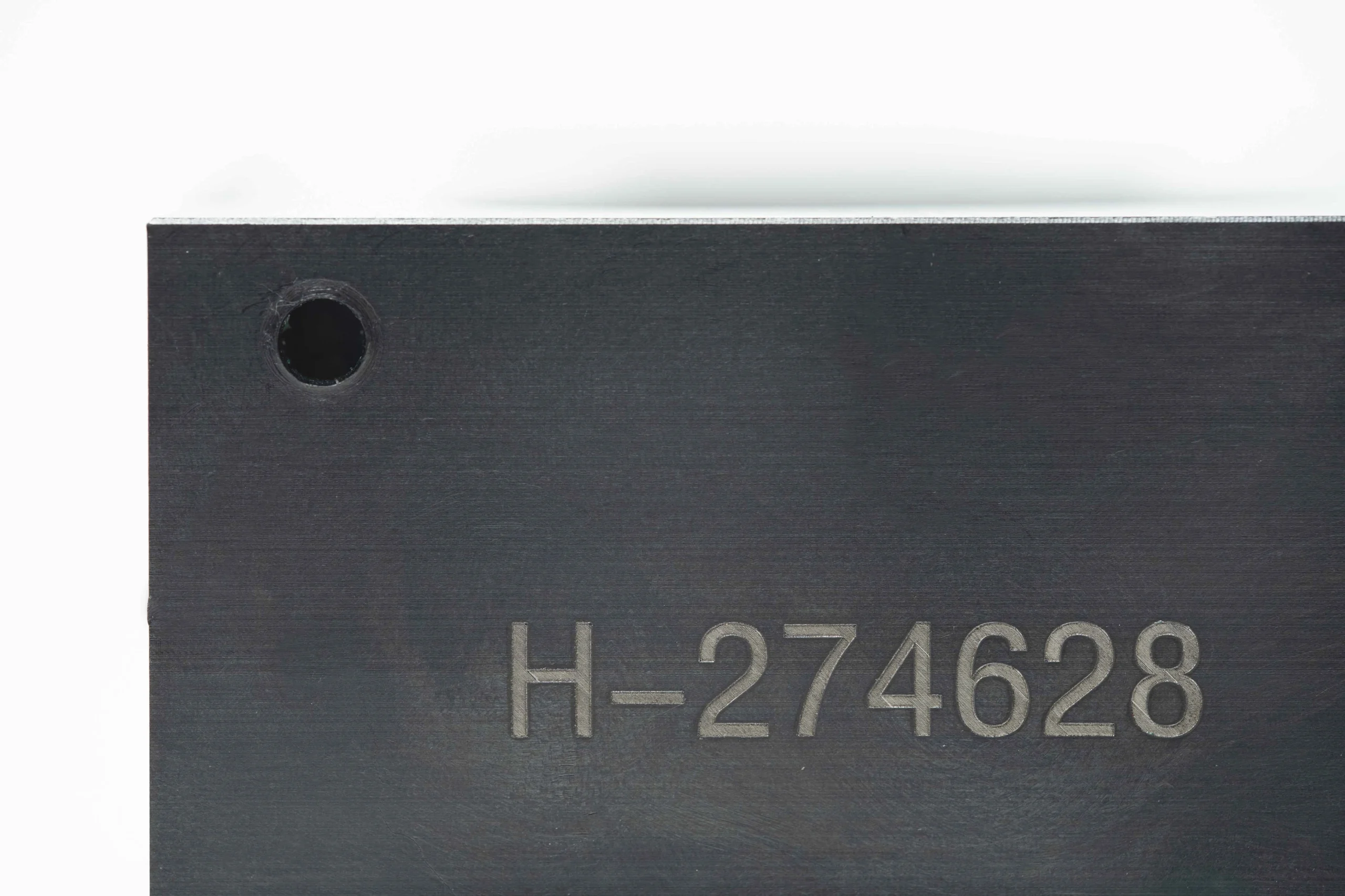
Part Identification
Laser marking, engraved references, serialized identification areas, and orientation marks can improve assembly control and traceability. Provide marking content, placement, character-size limits, finish constraints, and any revision-control requirements with the RFQ.

Protective Packing
Project-specific packing can help protect machined faces, ground surfaces, threaded features, and matched sets during transit. Confirm preservation needs, labeling format, quantity per pack, and any inspection-document separation requirements before shipment planning.
About SUUXIANG Precision Manufacturing
SUUXIANG is the sole public-facing brand of Dongguan SuuXiang Precision Mold Co., Ltd., established in 2010 in Chang’an Town, Dongguan, Guangdong, China. XiaoCheng Huang is the founder and legal representative. We help international engineering, sourcing and quality teams turn drawings and specifications into inspected custom CNC parts, precision mold components and connector-tooling components.
For CNC parts for motor test benches, our work begins with the drawing, 3D model, material, quantity and quality requirements. Project discussions focus on critical dimensions, datums, tool access, surface requirements, heat-treatment sequence, EDM or grinding needs, and the inspection evidence required before production commitments are made.
Our difference is disciplined coordination across CNC milling and turning, multi-axis machining, EDM, precision grinding, fitting and inspection. Rather than treating a drawing as a simple quotation input, SUUXIANG uses DFM, revision control and traceable communication to align the manufacturing route with the part’s functional and inspection priorities.

Core Capabilities for CNC Parts for Motor Test Benches
DFM Before Commitment
SUUXIANG reviews drawings and models before quotation to clarify datums, critical dimensions, mounting interfaces, tool access and tolerance stack risks. For CNC parts for motor test benches, this discussion helps align the proposed process route with the functional requirements.
- Confirm 2D drawing, 3D model, material and quantity
- Identify critical mounting, locating and alignment features
- Review access for cutters, probes, electrodes and wire paths
- Define surface and heat-treatment requirements before release

Coordinated Process Routes
Complex test-bench components may require more than a single machining setup. SUUXIANG plans the appropriate sequence of CNC milling or turning, EDM, grinding and fitting around geometry, material condition and inspection needs, subject to drawing review and verified project scope.
- CNC machining for structural forms and interfaces
- Wire or sinker EDM for inaccessible or detailed features
- Grinding strategy for controlled surfaces and allowances
- Fitting review where assembled relationships affect function

Critical Features Under Control
Functional interfaces deserve a defined control plan rather than a general tolerance statement. SUUXIANG evaluates datum strategy, mating relationships, surface requirements and inspection access so the method for checking critical features is considered alongside the machining approach.
- Establish datums from the functional drawing scheme
- Flag concentricity, position and flatness requirements
- Plan machining allowance before grinding or finishing
- Match inspection methods to specified critical dimensions

Traceable Delivery Records
Clear revision handling and inspection expectations reduce avoidable sourcing risk. Submit the applicable drawing revision, reporting requirements and target date with your RFQ; SUUXIANG can align manufacturing communication and final documentation with the confirmed order and inspection plan.
- Keep drawing revisions visible during project coordination
- State required inspection reports with the RFQ
- Document material, quality and delivery requirements
- Review changes before production proceeds

CNC Parts for Motor Test Benches: Drawing-Led Sourcing
Compare a documented engineering workflow with common quote-only sourcing risks.
← Swipe left or right to view →
CNC Parts for Motor Test Benches: From Drawing Review to Delivery
A controlled production sequence that keeps critical dimensions, process decisions, inspection expectations and revision status visible from RFQ through shipment coordination.
Review Drawings and Requirements
We review 2D drawings, models, quantities, application context, critical dimensions, datums, materials, surface requirements, inspection needs and requested delivery timing before quotation.
Confirm DFM and Process Route
The team identifies machining access, tolerance stack risks, heat-treatment sequence, machining allowance, electrode needs, wire paths and grinding strategy for the proposed component.
Plan Materials and Production
After requirements are confirmed, material requirements, revision status, production routing and inspection checkpoints are aligned to the approved drawing package and order scope.
Machine Critical Part Features
CNC milling, turning, multi-axis machining or micro machining are applied as appropriate, with process decisions guided by geometry, datum relationships and critical feature access.
Apply EDM and Grinding
Where required, wire EDM, sinker EDM, precision grinding and fitting complete hard-to-reach, hardened or fine-finish features while preserving planned stock and datum control.
Inspect Pack and Coordinate
Parts are inspected against the agreed plan, documented as required, protected for transit and coordinated for shipment with revision and delivery information kept visible.
How to Work with SUUXIANG
Move CNC parts for motor test benches from drawing review to coordinated production with clear technical inputs, inspection expectations and revision control.
Submit Your Technical Package
Send 2D drawings, 3D models when available, material, quantity, target date, critical dimensions, surface requirements, and relevant motor, sensor, or mating-component context.
Review DFM and Quote
Align on datum strategy, tool access, machining allowances, EDM or grinding needs, heat-treatment sequence, inspection method, revision status, and the proposed process route.
Approve First-Article Requirements
For projects requiring samples or first articles, confirm acceptance criteria, reporting format, measured features, and any fit-up checks before production commitments proceed.
Coordinate Production and Delivery
SUUXIANG coordinates the agreed machining, EDM, grinding, fitting, inspection, documentation, and delivery information against the approved drawing revision and verified inspection plan.
Quality Documentation for CNC Parts for Motor Test Benches
Customer Feedback on CNC Parts for Motor Test Benches
Approved customer case pending. This slot will document the verified drawing revision, inspection evidence, delivery result, and measurable outcome after the customer authorizes publication.
Approved customer case pending. This slot will describe the confirmed critical-dimension review, inspection-report outcome, and project metric once the buyer approves the quote and attribution.
Approved customer case pending. This slot will record the verified delivery-coordination result, revision-control outcome, and measurable program impact after customer approval for publication.
FAQ: Sourcing CNC Parts for Motor Test Benches
Practical answers for engineering and procurement teams preparing a drawing-led RFQ.
What information should I send for cnc parts for motor test benches?
Can you review drawings for cnc parts for motor test benches before quoting?
Is there a minimum order quantity for cnc parts for motor test benches?
How long do samples and production parts take?
What inspection reports can be supplied with custom machined parts?
How are payment and international shipping handled?
How is my drawing and IP protected during quotation and production?
Can SUUXIANG machine assemblies as well as individual components?
Complete Buyer’s Guide to cnc parts for motor test benches
Use this decision framework to specify critical components, evaluate machining suppliers, control risk and cost, and avoid sourcing mistakes that compromise alignment, safety, repeatability, and project schedules.
1. What Are cnc parts for motor test benches?
Two categories define cnc parts for motor test benches: custom mechanical parts made from drawings, and bought-in electrical or standard hardware. The machined group includes base plates, motor and dynamometer adapters, shaft couplings, sensor brackets, guards, cooling manifolds, cable-entry panels, locating blocks, and adjustment mechanisms.
One complete test bench is a working system, not a single CNC assembly. It also combines motors, drives, torque and speed sensors, power electronics, controls, safety devices, wiring, and commercially rated fasteners or bearings; the custom parts establish alignment, mounting stiffness, access, protection, and repeatable datum locations.
Since 2010, SUUXIANG has approached drawing-based work by reviewing the functional interface before selecting a process route. Custom-machine interfaces with unique geometry, controlled alignment, load paths, sealing features, or packaging constraints; source catalog hardware and electrical equipment when published ratings, replacement availability, and certified performance matter more than bespoke geometry.
2. Evolution of Motor Test Bench Components
1900s-era motor rigs commonly relied on a fixed base, coupling, load device and basic speed or torque indication. Those arrangements suited a single motor family, but their rigid shaft centerline, dedicated adapters and open rotating elements become liabilities when test articles, sensors or safety requirements change.
1960s automation and electronic measurement expanded test benches from mechanical proof runs into repeatable data-acquisition systems. Encoder feedback, current and temperature channels, interlocks and controlled loading made datum relationships between motor, coupling, torque transducer and load machine directly relevant to measurement quality.
2020s development programs often require modular fixtures, guarded work zones and quick changes across prototypes or variants. CNC parts for motor test benches therefore need defined locating faces, repeatable interface patterns, cable and coolant routing, thermal-growth allowances and service access; copying a legacy bracket without reviewing its load path, alignment stack and guarding envelope can slow reconfiguration or compromise safe operation.
3. Types of cnc parts for motor test benches
CNC parts for motor test benches should be grouped by the interface they control. Each drawing must identify datums, purchased-component envelopes, loads, and inspection priorities before process selection.
Baseplates And Frames
Baseplates locate motors, brakes, and rails. Define mounting grid, flatness, load paths, and leveling interfaces.
Motor And Adaptor Plates
Adaptor plates mate motor pilot diameters to dynamometers. Control bore position, pilot fit, bolt pattern, and axial stack.
Shaft Couplings And Hubs
Hubs transmit torque between purchased shafts and couplings. Specify bore fit, keyway or spline, runout datum, and balance requirement.
Sensor And Encoder Mounts
Encoder mounts hold feedback devices relative to a shaft. Define sensor model, bolt pattern, sensing gap, concentricity, and cable exit.
Guards And Enclosures
Guards separate operators from rotating assemblies. Provide clearances, fastener access, viewing needs, and purchased interlock interfaces.
Cable And Fluid Management
Manifolds, clamps, and brackets route cooling lines and harnesses. Show connector geometry, bend clearance, port threads, and service access.
4. Materials for cnc parts for motor test benches
Three duty zones usually drive material selection: the load path, the locating interface, and the thermal or electrical boundary. For cnc parts for motor test benches, repeatable alignment and operating environment outweigh a universal material ranking.
| Material | Best-Fit Duty | Key Tradeoff |
|---|---|---|
| Aluminum alloy | Light structures; thermal brackets | Low weight; lower stiffness |
| Carbon steel | Rigid bases; precision interfaces | Strong and economical; needs corrosion protection |
| Stainless steel | Corrosive or washdown areas | Corrosion resistant; slower machining |
| Engineering plastic | Guards; electrical isolation | Insulating; lower stiffness and heat resistance |
Match Material To Duty
6061 aluminum suits light fixtures, covers, and heat-spreading brackets when moderate stiffness is sufficient. Steel is usually preferable where clamp load, shaft reaction, or long-span deflection governs.
304 stainless suits wet or corrosive laboratory environments, but costs more machining time than aluminum or carbon steel. Specify the actual exposure, temperature, and load case on the drawing.
Protect Critical Interfaces
0.02 mm-level positional requirements should be tied to datums, joint design, and material stability rather than alloy name alone. Hardened steel inserts or ground interfaces can preserve repeated locating surfaces where aluminum would wear.
Anodizing improves aluminum corrosion and wear resistance, while paint, plating, or passivation should be selected for the environment and electrical-contact needs.
Use Plastics Deliberately
Engineering plastics can isolate electrical paths, reduce handling weight, and form guarded covers. Their lower stiffness and greater thermal expansion require clearance, support, and temperature limits to be defined before release.
5. Custom Features and Finishing Options
Two feature groups require separate drawing control: interfaces that establish repeatable assembly, and finishes that protect or identify a part. For cnc parts for motor test benches, specify the function before selecting the process.
| Option | Primary Function | Drawing Information |
|---|---|---|
| Engraving | Traceability | Text, height, depth, location |
| Anodizing or plating | Protection | Type, thickness, masked areas |
| Passivation | Stainless surface condition | Material grade and applicable specification |
| Powder coating | Durable coverage | Color, thickness, mating exclusions |
| Edge treatment | Safe handling and fit | Break-edge range or burr limit |
Locating And Interface Features
Dowel bores establish repeatable position; threaded inserts carry removable fasteners where base material or service cycles warrant them. Define datum references, bore type, thread standard, engagement depth, and allowable positional tolerance.
Keyways and slots transmit torque or provide adjustment. Dimension their width, depth, corner-radius requirement, mating-part relationship, and any burr limit from functional datums.
Identification Versus Protection
Engraved labels support asset identification and revision visibility; they are cosmetic unless a legibility, depth, location, or contrast requirement is stated. Keep labels clear of sealing, bearing, and grounding interfaces.
Anodizing, plating, passivation, powder coating, and edge breaking serve different durability or corrosion-control purposes. Do not assume a cosmetic coating is electrically suitable or dimensionally neutral.
Finish Callout Checklist
Three drawing elements prevent ambiguous finishing: the applicable surface area, the finish specification, and masked or critical interfaces. State color only when appearance matters; state thickness, preparation, post-finish dimensions, and inspection method when function matters.
- Identify coating standard and color reference
- Mark masked threads, bores, and grounding faces
- Set edge-break range or maximum burr
- Attach revision-controlled label content
6. Construction Quality Elements That Matter
Functional datums, not cosmetic faces, should locate every motor, bearing housing, torque sensor, and guard. For cnc parts for motor test benches, each tolerance should protect alignment, vibration behavior, sensor position, service access, or operator safety.
Datum And Geometric Control
A defined mounting face, shaft axis, and locating feature create a usable datum scheme across plates, brackets, and housings. Flatness supports stable seating; perpendicularity and concentricity prevent offset loads that can distort coupling alignment or measurement results.
Fits, Threads, And Edges
Bearing bores and mating shafts require the specified fit class, material condition, and inspection method; avoid a blanket tight tolerance on unrelated features. Threads need full engagement, clean starts, and accessible gauge paths, while deburred edges reduce assembly damage and handling risk.
Finish And Inspection Access
Surface finish matters where bearings seat, sensors reference a face, seals contact, or adjustment slides must move predictably. Specify only function-driven roughness and edge requirements, then leave probe, gauge, and tool access so inspection and future service remain practical.
7. Choosing a Manufacturer for cnc parts for motor test benches
Two questions should govern supplier selection: can the shop repeatedly manufacture and verify every critical interface? For cnc parts for motor test benches, assess evidence from the drawing review through final packing, not the quotation alone.
Review The DFM Response
1 drawing review should identify datums, tolerance conflicts, tool access, clamping risks, and inspection points before release. Ask the supplier to flag ambiguous callouts in writing and propose a controlled disposition.
Match Process To Interfaces
3 process routes—CNC machining, EDM, and grinding—may be needed when bearing seats, alignment faces, or fine features have different access requirements. Confirm the proposed route, material traceability needs, and heat-treatment sequence against each critical interface.
Control First Parts And Changes
1 first-article plan should state measured dimensions, datum setup, instruments, report format, and acceptance criteria. Require revision-controlled communication for prototype-to-low-volume changes, realistic lead-time updates, and packaging that protects finished reference surfaces.
8. Common Buyer Mistakes to Avoid
Eight release errors repeatedly create avoidable rework in motor-test-bench assemblies. Resolve datum, interface, finish, clearance, inspection, and commercial assumptions before a purchase order is released.
Define Datums And Interfaces
Two drawing views are rarely enough when a bracket locates to a motor, encoder, or fixture. Missing datums and mating-part data can shift hole patterns; provide models, interface dimensions, and a datum scheme.
Specify Fit And Finish
One unnecessarily tight tolerance can require grinding, EDM, or extra inspection without improving function. State functional tolerances, surface finish, coating, thread class, and standard-hardware clearances; confirm interference risks with an assembly check.
Release Inspection And Cost Criteria
Three absent inspection criteria leave acceptance open to interpretation after parts arrive. Identify critical dimensions, measurement method, reporting requirements, revision level, and sampling expectations before release.
One low unit-price quote can omit setup control, inspection evidence, or delivery coordination. Compare the quoted scope, process route, documentation, and total risk—not price alone.
9. From Design Release to First Article
One controlled launch package prevents production from starting on assumptions. For cnc parts for motor test benches, engineering, quality, procurement, and assembly should approve the same revision before first article.
Define The Released Package
Before release, engineering records duty cycle, speed, torque, temperature, mounting loads, vibration, and mating interfaces. Assembly confirms access and service constraints.
Each drawing identifies datums, critical-to-function dimensions, GD&T, threads, surface requirements, and revision. Attach native or neutral 3D CAD.
Close DFM And Quality Handoffs
During RFQ, SUUXIANG reviews tool access, clamping, machining allowance, EDM or grinding sequence, and inspection feasibility. Procurement issues the controlled drawing package.
Before machining, engineering approves material, heat treatment, finish, and any deviation. Quality aligns measurement methods, report format, sampling, and traceability.
Approve First Article Changes
At first article, quality compares measured results with the released drawing and flags exceptions by feature and datum. Assembly verifies mating fit, cable clearance, and functional installation.
After review, program management logs disposition, revision owner, and effective date. Procurement releases repeat orders only against the approved revision.
10. Pricing cnc parts for motor test benches
1 RFQ can generate very different pricing for cnc parts for motor test benches when datum-dependent features require multiple setups, EDM, grinding, or expanded inspection. SUUXIANG should price the released drawing, revision, material condition, quantity, and reporting requirements—not a generic part name.
3 cost-reduction actions usually preserve function: assign tight tolerances only to CTQ features, consolidate compatible setups, and specify the inspection evidence actually needed. Keep mating interfaces, safety-related geometry, and repeatability requirements explicit; relax nonfunctional dimensions only after design approval.
| Driver | Illustrative tier | Price effect | Lead-time effect |
|---|---|---|---|
| Part complexity | Simple / multi-setup | Lower / higher programming and machining | Shorter / longer |
| Material | Free-machining / hardened or difficult alloy | Lower / higher tooling and process cost | Limited / added processing |
| Tolerance and finish | General / CTQ, ground, EDM, coated | Lower / higher control effort | Standard / added operations |
| Inspection | Visual / dimensional report or first article | Lower / higher metrology effort | Minimal / added review |
| Quantity | 1–5 / 25+ identical parts | Setup spread across more pieces | First-piece effort / repeat production |
CNC Parts for Motor Test Benches: Request a Technical Quote
Upload your drawing with material, quantity, critical dimensions, inspection requirements, and target delivery date for an informed RFQ review.